
Dane Kouttron
Project Started: 06/2020
Reviving a Type A Machines - Series 1 3D Printer
Lab clean-outs are the best
The ever excellent DGonz spotted this printer during a lab clean out in the before times, I had not heard of Type A Machines, but a 12" cube build volume is something I couldn't say no to. I was looking for a 'new' lab printer, as I had been using a Makerbot replicator 2 that had been patched together too many times to count.
The following details efforts to bring a ~2012 3D printer into the modern (2022) eraCheckout below for some hardware details, electronics upgrades, mechanical modifications and some comments from a former Type A Machines Employee. |
||
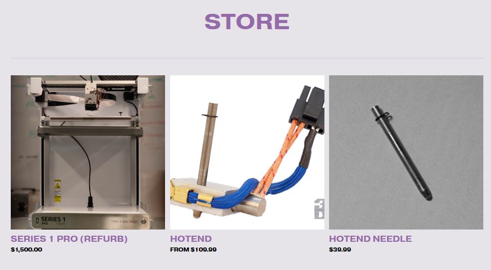
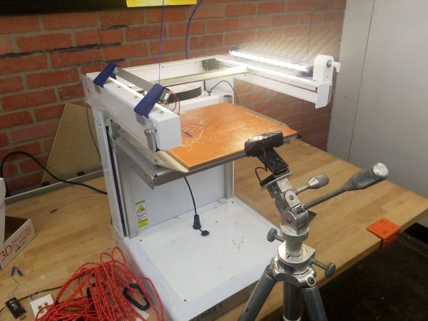
A quick introduction and some historyThe printer shown below is after a few basic onboard lighting modifications. A lot of these images / videos were taken before I had lighting stands and the imagery is a bit rough. That said the printer itself looked fairly great from the outside, large steel brackets and stamped parts, linear guides and a flat flex cable for extruder power and signaling. A heated glass bed? Quite the beast. Before we jump in, lets detail what we can find out about this printer. Its not terribly common but it was an early prosumer grade printer with an associated price tag. Note the little blue add in lights and the lil knob were not stock and early add-on's. Here's a screenshot from Adafruit and a link to the old product page Adafruit Store. There's an interesting write up about he company here [link]. Type A Machine's website is long since retired and now re-directs to solidstateprinters.com They appear to sell type a machines printer parts on their store [link] and it looks like it may be run by a former employee running type-A's in a print farm. It looks like these printers were designed and made stateside. We have two documents from the net that are interesting: A User manual [local link] and a CURA tuning guide [local link] 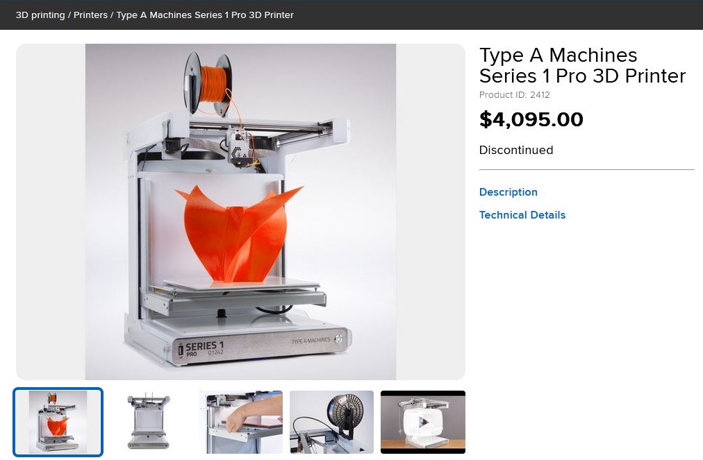
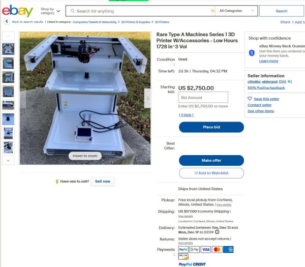
From the outside, there is nothing indicating what the printer is doing from the outside. No display or series of indicators, just a big power button. This is intended to be completely network controlled printer. When I first plugged this in I was greeted with... nothing. The power light indicating the 24 V supply was enabled but nothing did anything. The beagle bone does not actually have a display output, so my only option is, connect it over Ethernet to a network and hope it DHCP's well. While i waited around for it to wake up i checked if there were other Series 1 Printers hiding on the eBay. Interestingly they are still fetching for quite a lot. 
Fortunately after a bit of eBay distraction, it woke up one of the three times I powered it up and my DD-WRT main page showed it on the network! The camera even worked. So I now have a printer that responds over the network but is somewhat finicky. I grabbed screen captures of all the configuration menus while things while things were behaving, and then fired up my first print, a freshly sliced (in CURA) shark comb. I reasoned the 5V supply to the beagle bone may have been under-volting and used a 5.1 V raspberry pi power supply in its place. 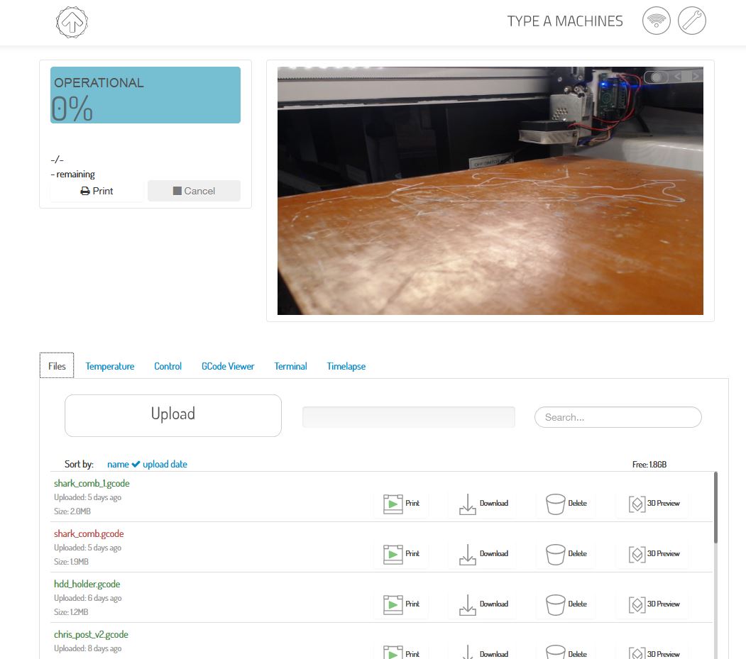
The "Type A" used a streamlined version of CURA. I kept the default installer and have a local copy here [link]. This is based on CURA 1.5.0 and does still work. It's kind of marvelous how far the CURA slicer has come from when this version was born in ~2015 to present day [2022]. I debated using an existing sliced file that was still on the machine, but I was not sure what they were using (filament) and I wouldn't have much of an idea as to what their print First Print with default CURA slicerUsing the stock settings in the modified type-a-machines Cura build I just yolo'd it. It turns out, aside from some z-offset calibrations and a thorough cleaning of the build platform we have a working printer! Note the video below is sped-up after the first nozzle-cleaning extrusion. We're printing white Dremel brand PLA. There's something on the build plate, which is normally glass. I did some digging and it looks like its the "print on glass with elmers glue" approach. Elmers glue does not really bond to glass itself but it does provide a surface for the PLA to mate to. I wiped the surface down with some IPA and sent the print sliced from type-a-machines Cura build. While I did some bed-leveling before hand, this legitimately just worked. The stock extrusion settings are fairly conservative (60mm/s) but its just working happily. The CURA build actually featured a 'send to printer' mechanism which uses UPNP discovery, but that seemed Stock ExtruderThe extruder is really interesting. Its unfortunately very custom but nice extruder tied to a ribbon cable breakout board. Thermistor, 24 V extruder heater supply, fan control and stepper drive all travel down the thin flex cable between the printer and the flying extruder head. These breakout to their respective hot-end connectors on a small FR4 PCB. The hot end is a 'needle' design, where a standard 24 V cartridge heater + thermocouple live on a hot end block and a small stainless steel tube with a 0.4 mm end orifice. I love the design where the extruder is replaceable and connector-ized. The 'needle' style extruders were not as common, the heat-break occurs in the blower metal assembly above. The whole extruder is held in place by an overhead e-clip ring. Two normal-ish 0.1" spaced 12 V connectors are used for the heat-break fan and the print cooling fan. 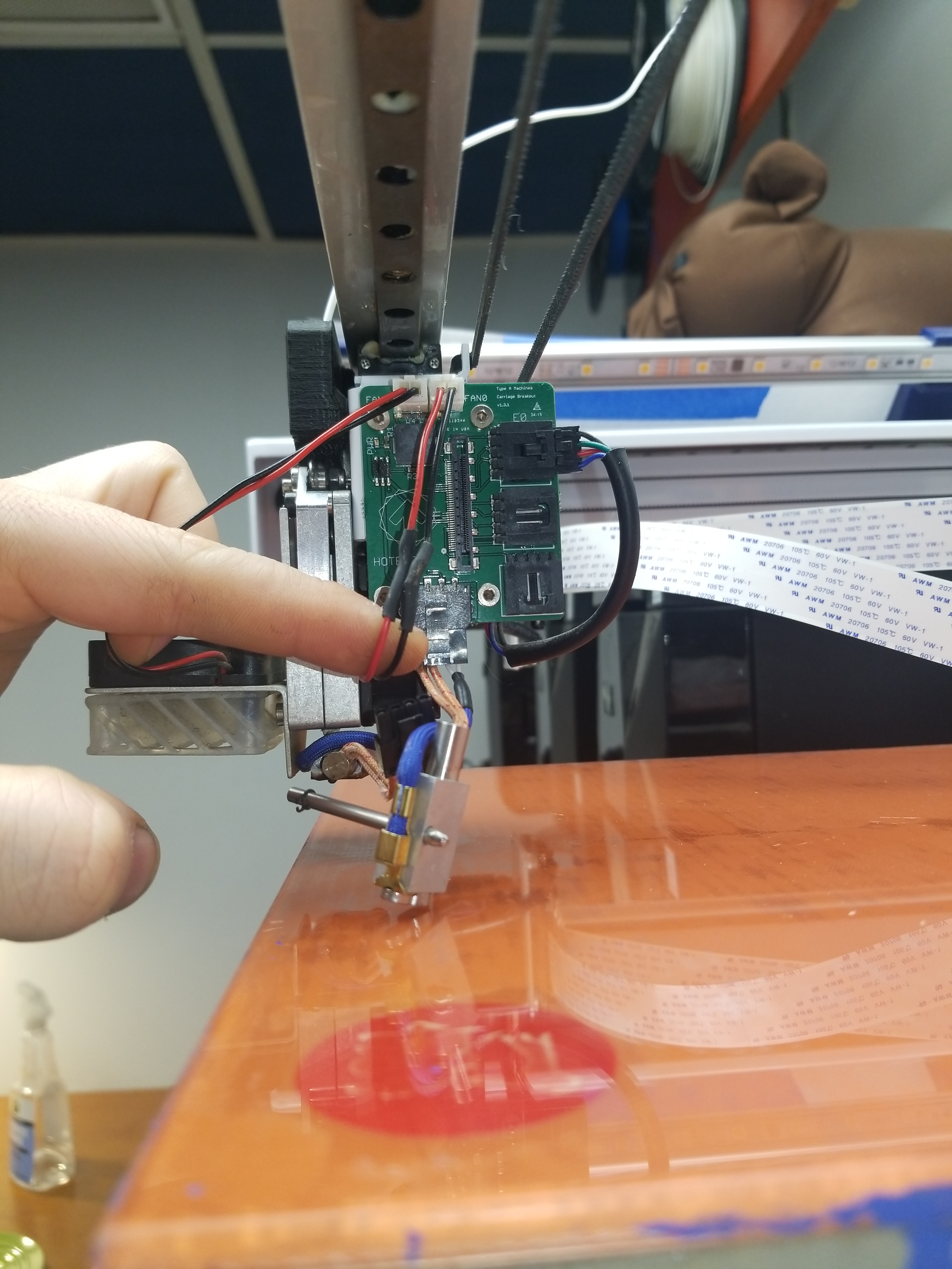
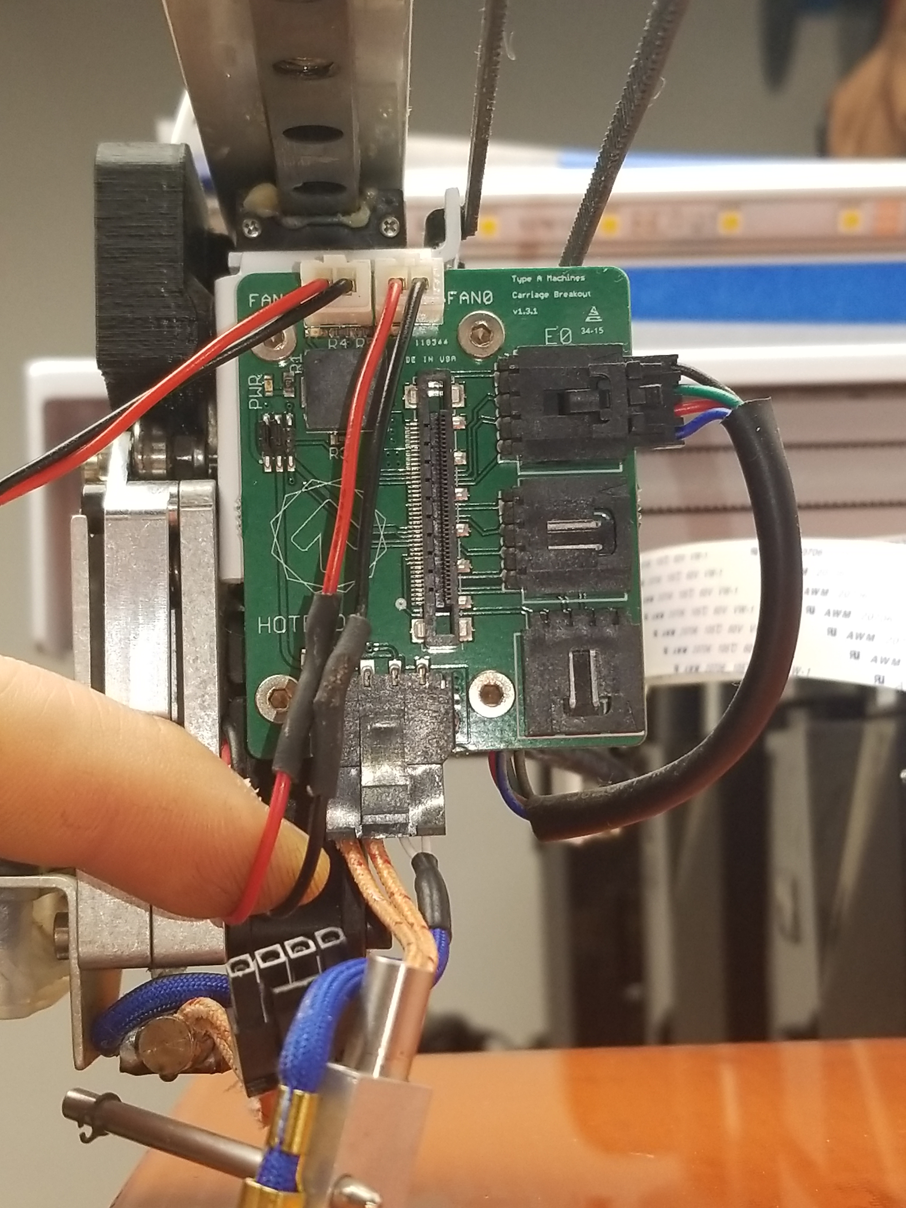
My biggest concern was the amount of force the connector / flexible ribbon cable sees and after 8 months of use the flat flex cable connector (on the cable side) did end up failing. Incredibly fortunately I was able to purchase one on amazon [link]. Note you want the 41 conductor / 41 pin variant. Otherwise this just works, which is convenient. I'm somewhat surprised the ribbon cable is 'self supported', a thin lightweight cable guide would be excellent if it took the load off the cable connectors / the flat flex cable connectors. 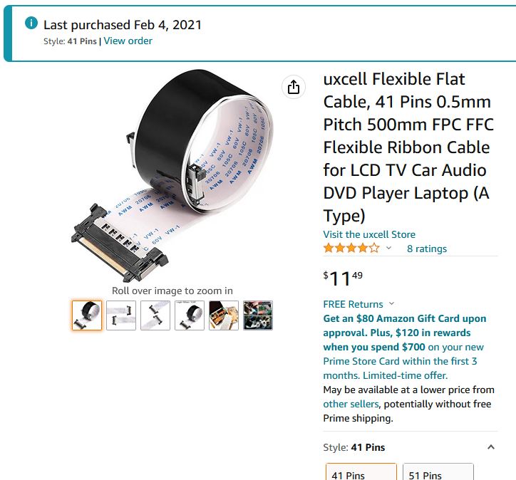
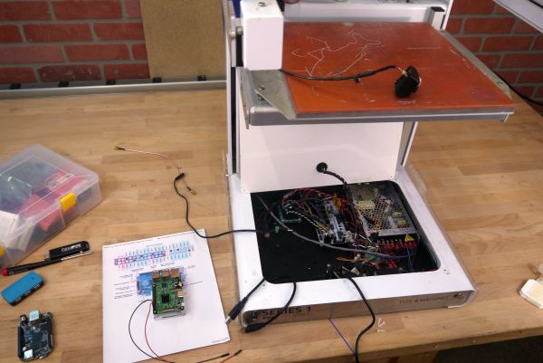
Opening up the electronics bayWow what is going on here. While the mechanicals appear planned out and really well done, the electronics are a medium zoo. Its unclear if this is the stock configuration or if this was modified by MIT folk. Its a really weird mix of organized and chaos. The base plate has all the mechanical pickups for the beagle bone single board computer, but aside from that and the RAMPS stepper board, everything else is flying in the breeze. The RUMBA board appears to be a 6 channel (5 stepper drivers populated). Interestingly these are the nice-er silent step drivers from Trinamic, which at the time this was manufactured, would be rather new. The electronics bay was a zoo. Maybe this was a prototype? While the image is a bit dark below you can somewhat see the piecemeal state of the cabling. Is that a USB hub hiding in there with a USB wifi stick floating in place? Is that an RC airplane BEC supplying power to the main control computer? 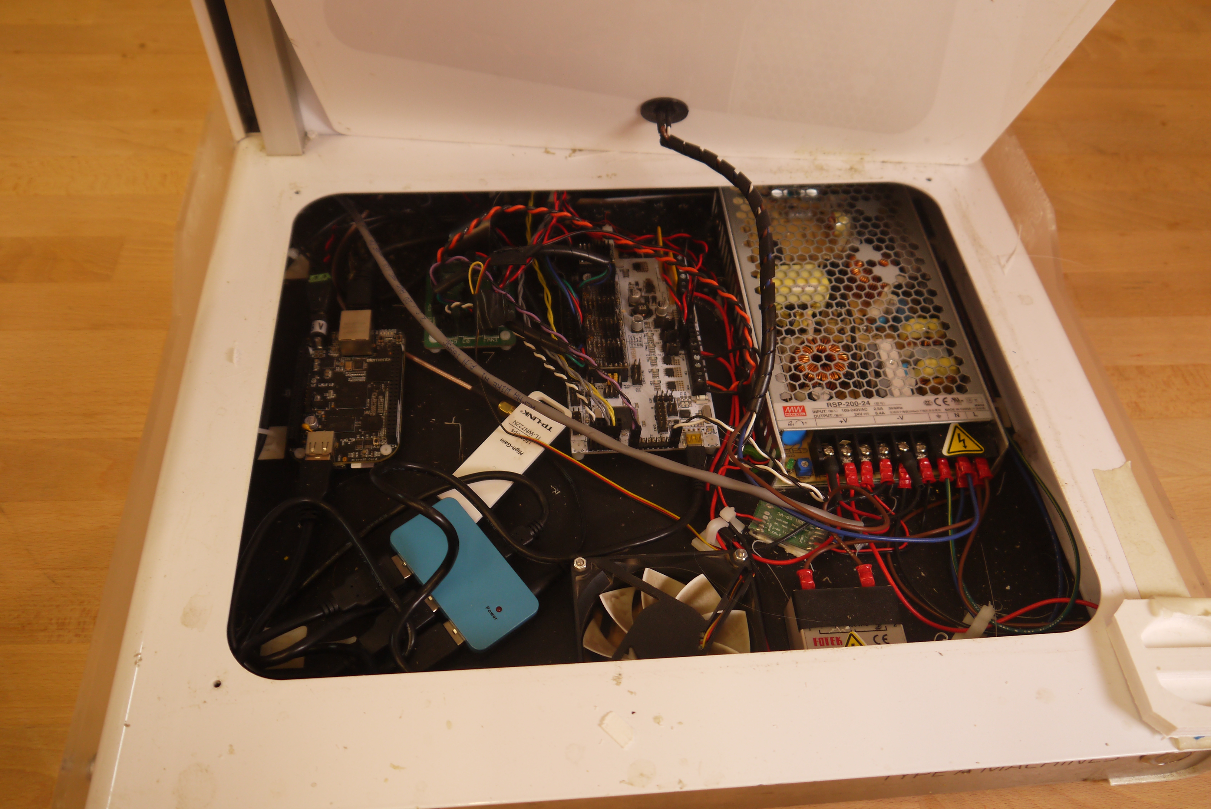
For a power supply we have a fan-less 24V Meanwell, supplying power to both the RUMBA and beagle bone. How is the 5V beagle bone getting power you ask? Through a HOBBY GRADE BEC. This is pretty mediocre, there are a lot of off the shelf 5v dc/dc step down modules but R/C hobby grade ones are notoriously bad, so much so there are people who run a battery instead of a BEC for servos. The beaglebone has a single USB output so a budget USB hub is used, also fed from the 5V BEC. On the USB hub we have a WiFi card piped out to the back via an SMA extension , A USB extension for a front panel mount USB A connector, a USB webcam and the USB cable running to the RUMBA board.
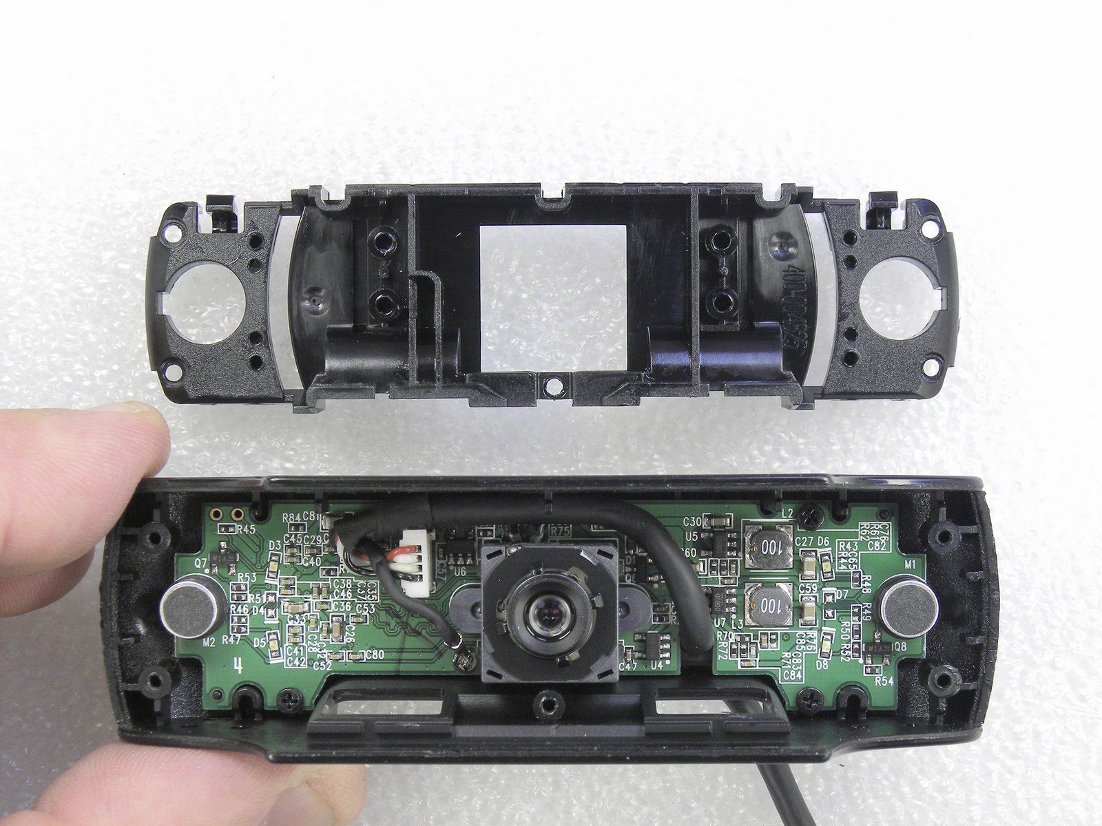
Replacing the Default CameraThe particular camera that came with this printer was a fairly basic generic webcam in a printed enclosure. It was incredibly potato resolution so I opted to upgrade to a Logitech C920. I lucked out and got two C920's in late 2019 for 50$, about a year later those two cameras were nearly 4X the price due to the pandemic and everyone needing a webcam for remote work. The C920 is a fantastic camera, adjustable focus and great picture quality while not requiring USB3.0. Having the camera as a USB2.0 makes it way easier to use on a low power single board computer. 
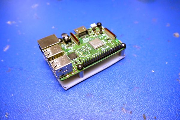
Making a new mount for a raspiI was really impressed, they added what appeared to be threaded receptacles to the base plate for the stock beagle bone. Unfortunately these didn't actually line up with the Raspberry Pi mounts so i made a quick adapter to hold it in place. It probably would have made more sense to use one of those heatsink-cases, but I did not have any on hand. The pi really wants M2 / M2.5 threaded mounts which can be a bit tricky to find. The small acrylic plate was double-sided taped to the base of the case, power network and USB was routed to the pi from there. Thankfully this no longer needed a USB hub as the pi 3 can support 4 devices natively (external webcam, printer USB-serial link and front facing USB port). I didn't opt for keeping the USB-Wifi card as I had Ethernet available nearby. With the new raspi installed where the beaglebone previously lived, I grabbed a CUI 15W DC/DC to power the single board computer from the 24 V rail. I followed this guide [link] for the octprint install process and the stock install detected everything. The C920 webcam does require some extra fiddling to get the manual focus to work correctly, otherwise no hiccups on the install. 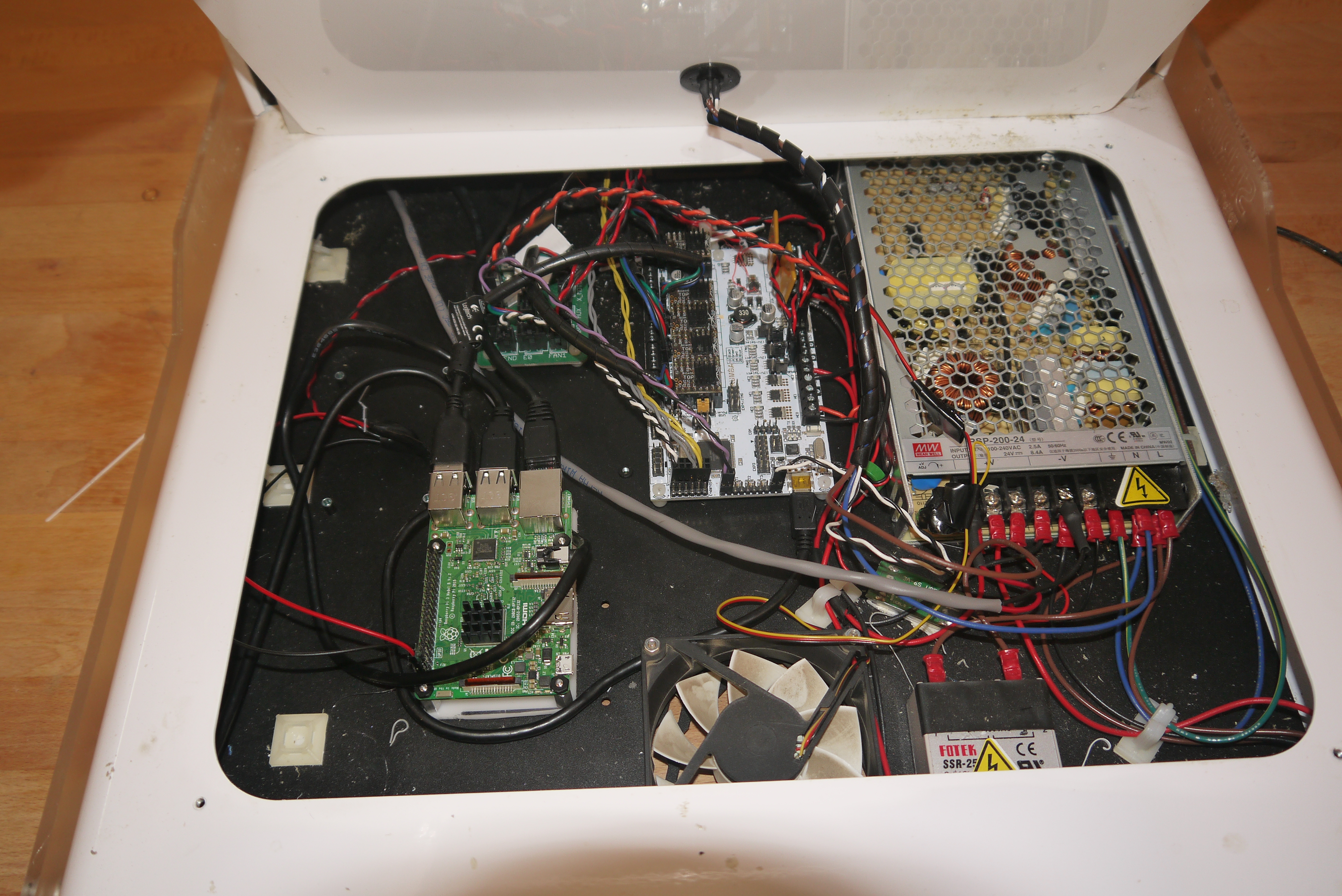
First Print with new-OctoprintWith the raspberry pi installed in place of the beaglebone, it was time for an inaugural print. I printed a battery end-cap adapter from some white PLA. Surprisingly everything worked, this is kind of the beauty of hardware with an open source heart. The stock controller being a RAMPS board has a predictable and somewhat known connector setup. Limit switches and stepper drivers just matched up with the defaults. Normally swapping out 'the control computer' of a piece of test equipment results in a complex series of hunting down software, drivers finding an old kernel etc. This just worked with a brand new brain. I was still new to printing on glass and I found it somewhat of a slow start to get used to. Glass and PLA work remarkably well if the surface is clean, especially grease free, the previous users had been using what appears to be an elmers glue-ipa slurry to increase print bed adhesion. At the time magnetic PEI sheets didn't quite exist. The magnetic PEI build platforms somewhat solve a lot of issues with bed adhesion, as they provide a removable surface that is easy to re-attach. The flexibility of the PEI sheet also completely removes the "chisel away at the build surface to remove a part" issue with over-bonded prints. I toyed with elmers-glue-isopropyl mixes and temporarily super gluing to the build platform and it was always a bit hit or miss. Part of this is tied to not having a bed leveling probe, as any non-planar parts of the bed cause issues with filament-to-bed adhesion. Stock Extruder issues
The stock extruder worked fairly well out of the box, no huge hiccups, but the way air is intended to flow past the extruder to cool the plastic is really weird. You can get away with a single blower fan, so long as it cools the plastic all around the extrusion area. High speed printers, like the Voron and the like use huge blowers to help transition the plastic from molten to solid quickly, so that subsequent layers are not printing on top of a soft surface. For large prints you do not actually need equal cooling on all sides of the extruder as by the time you return to the part that was molten it has cooled sufficiently on its own. This however becomes an issue when you have long tall extrusions.
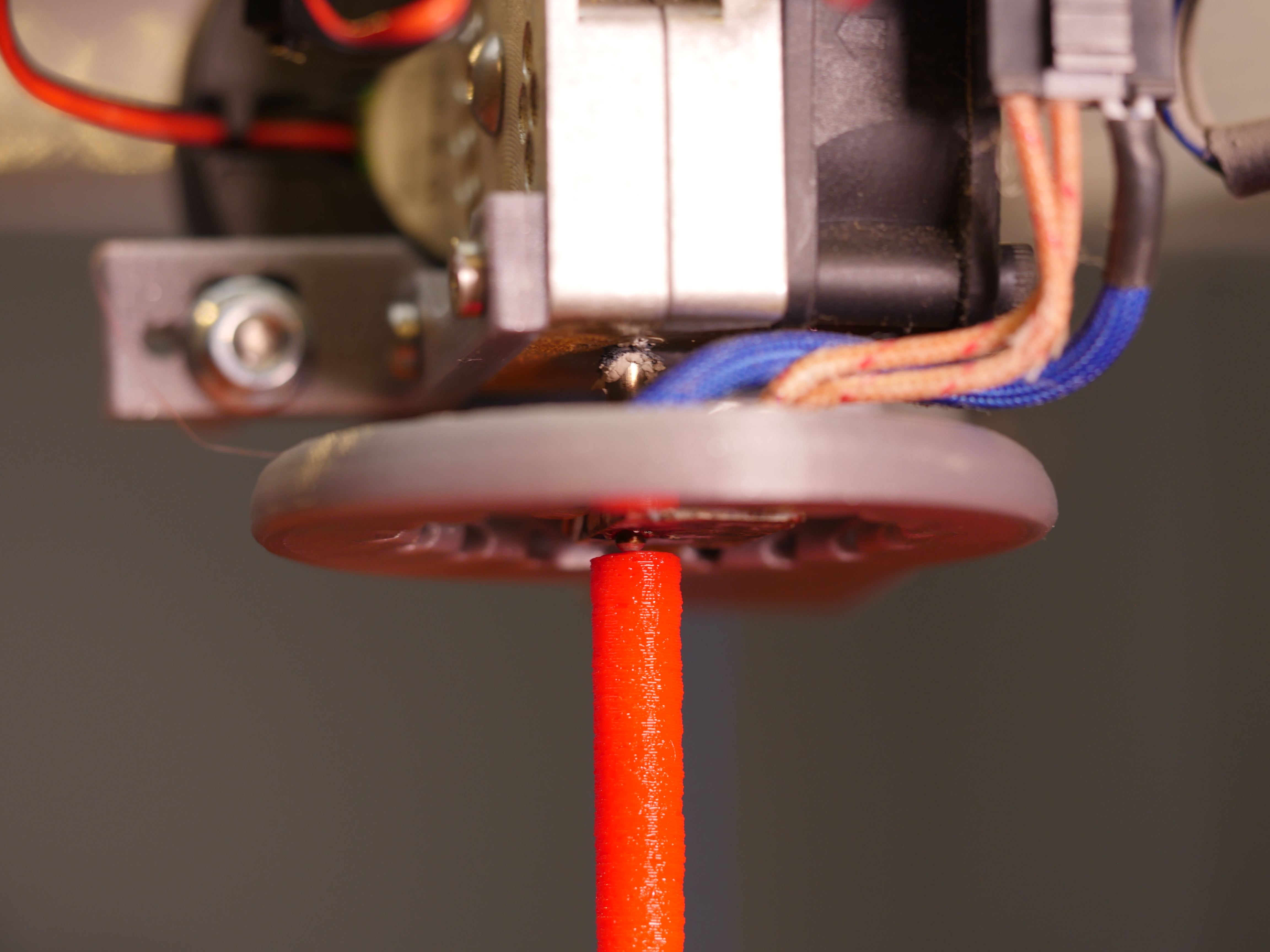
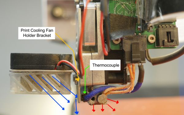
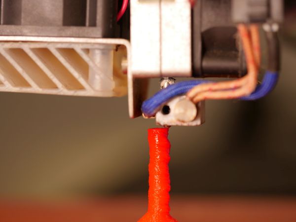
Lets take a look up close and see what the print-head is doingIts easy to see what is happening when you look up close. I quickly sketched up a "simple test print", with the goal being printing a 0.25" rod. The base has a significant amount of area and a raft to ensure that bed adhesion is not the limiting factor. Interestingly in this test print we see the 1" diameter base does not have any thermal buildup issues but as we taper down to 0.25" we see the issue emerge. Lets take a quick look at the thermal path and why this might be happeningIn the diagram below you can see the aluminum folded bracket that holds the part cooling fan on blocks the thermocouple on the hot end. This initially looked a bit odd, but I considered that it was possible a higher flow rate fan might solve the problem without significant intrusion. The fan guide was a curious part, it appeared to be SLA printed, including some of the little SLA printing remnants. Maybe they were concerned about using an FDM part near the hot-end? 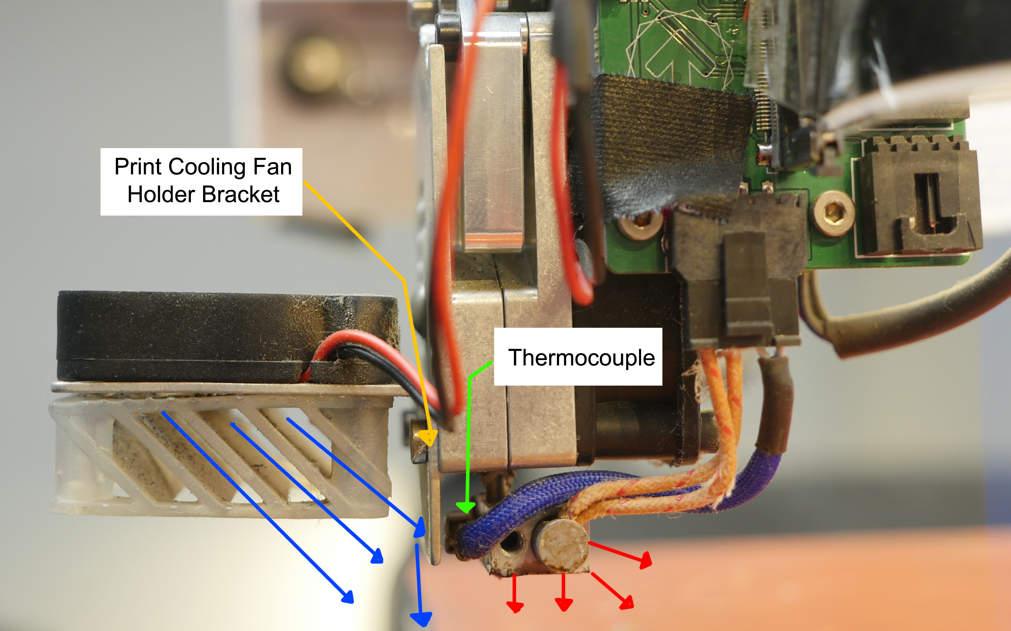
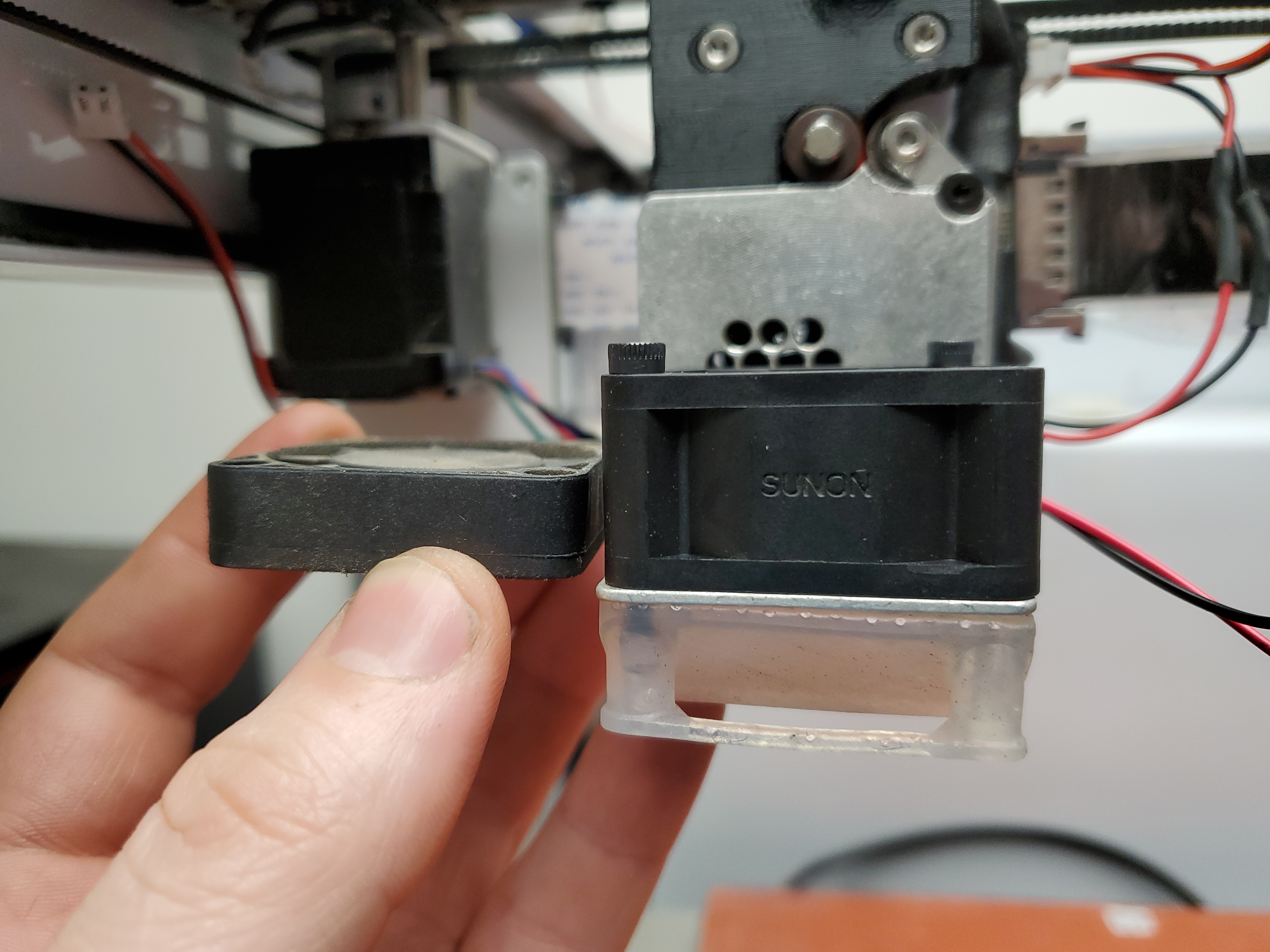
In the diagram above we see that there's a plate blocking the fan from directly hitting the thermocouple that's measuring the extruder temperature, which makes sense, as the thermal path to the thermocouple is not exactly direct. Some of the cooling air does make its way down to the part but only from one side and fairly indirectly. Can we just swap out for a higher CFM fan to get around this issue?Knowing what we know now, lets just increase the fan flow rate, that might have enough blow-by to make this issue go away. The 40mm stock fan is fairly simple, its a 12V JST connected fan, and getting a drop in replacement with a higher CFM is fairly easy to do. We do need longer bolts for holding the fan in but that's easy to sort. 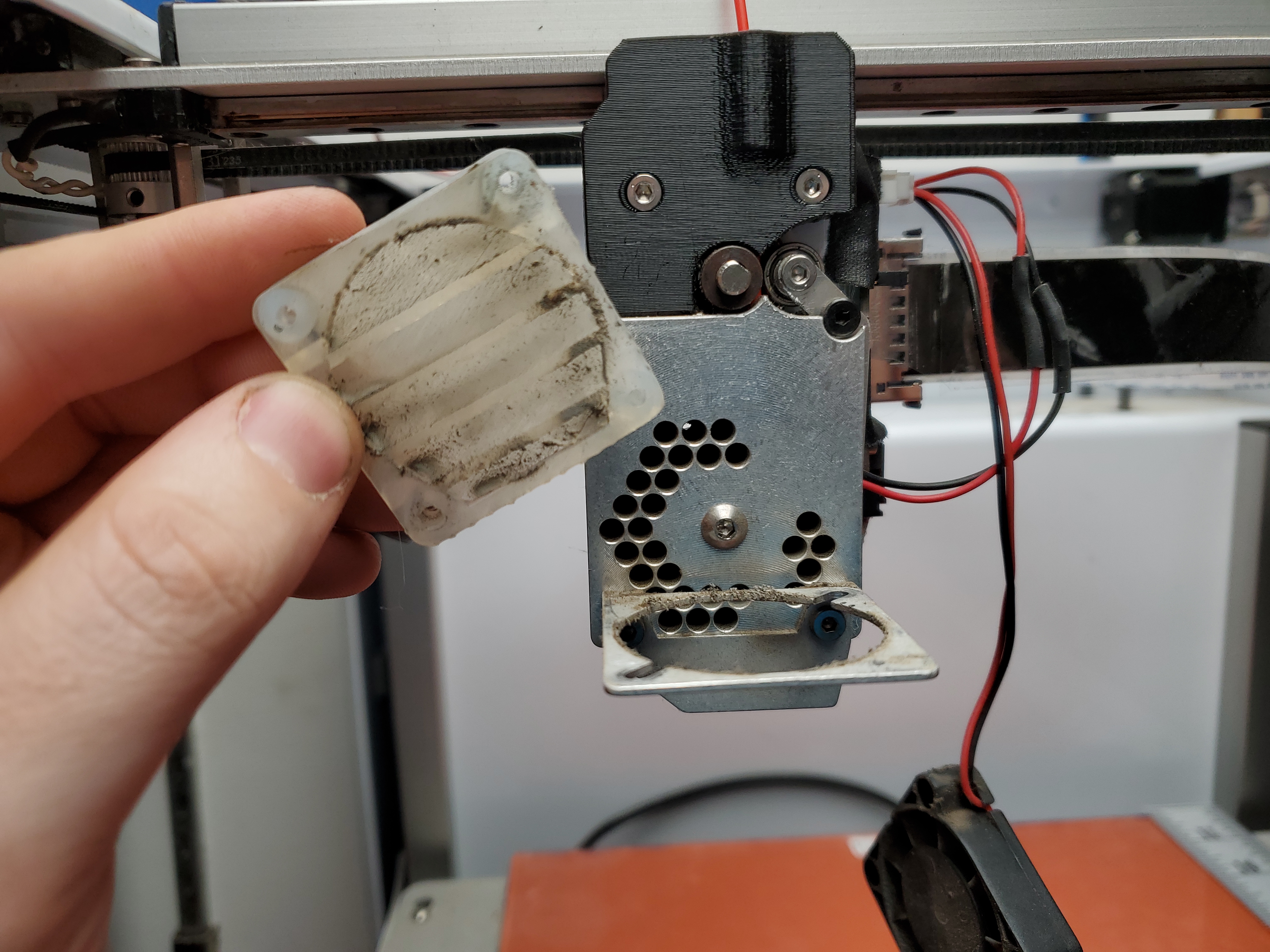
I disassembled the stock print cooler and washed off the fairly gross air fan guide, installed the larger fan, re-terminated the connector as the polarity was reversed then fired up the printer. It's better but the issue isn't really resolved. When I started with fan-speed 100, the printer was struggling to keep the hot-end up to temperature. I ended up having to back the fan speed down to ensure the extrusion was not happening at the wrong temperature. Has anyone else had this issue?Looks like Adafruit had a similar issue, here's a thingiverse file for a blower modification to the extruder. [Link] This part is surprisingly easy to print, I was a little concerned with all the overhangs. I was able to print this on a friends Prusa Mk4, but a clapped out Ender-3 was also able to tackle this without a problem. Unfortunately it seems to mechanically collide with the frame of my printer. Ignoring that it prevented x-y homing from working, I fired up a print. 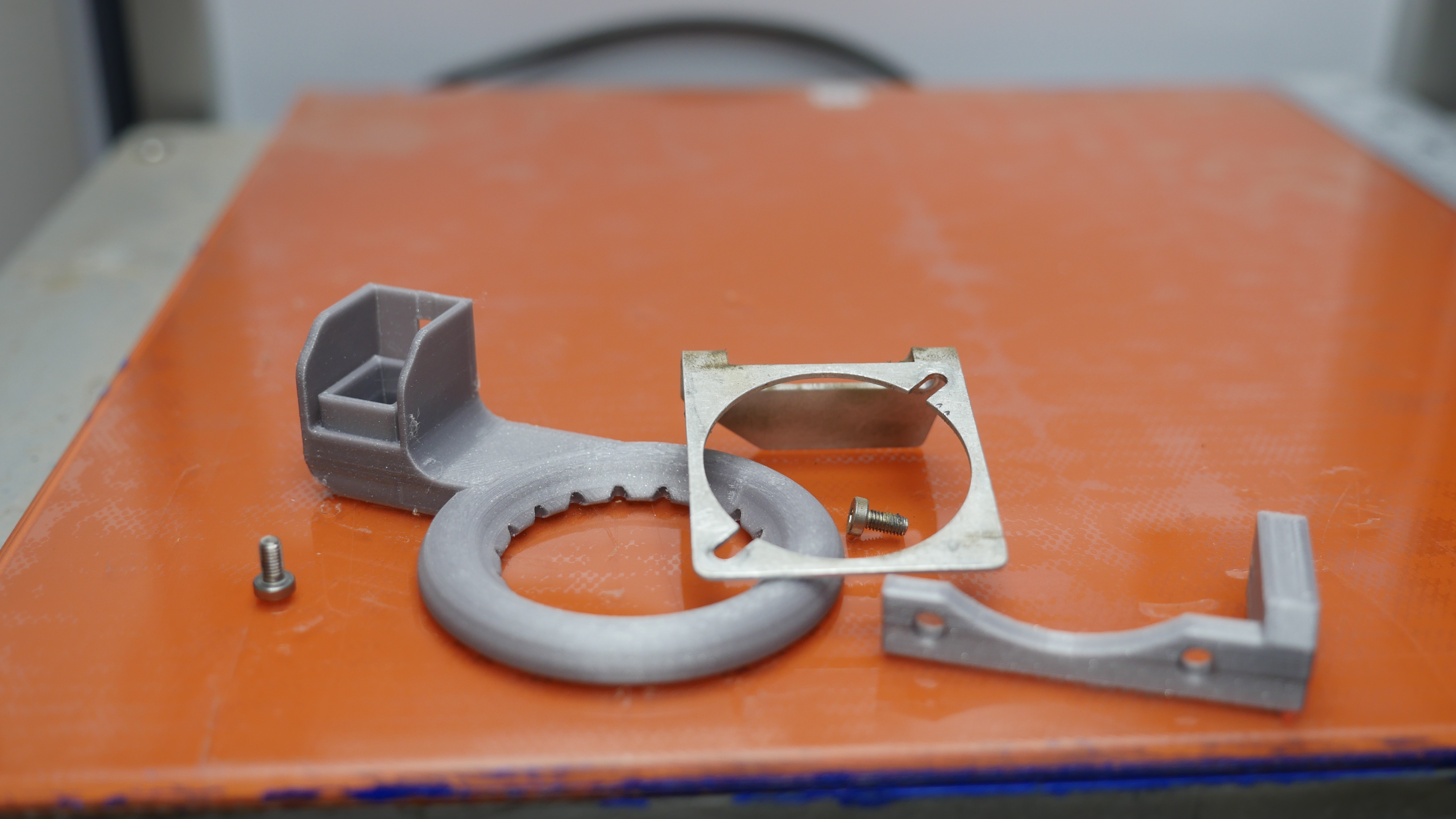
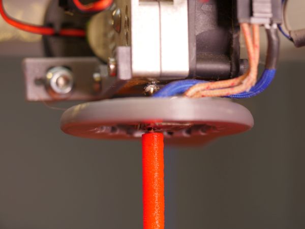
This looks like an absurd alien saucer while printing, really quite curious to watch. This seemed to work, it looks a bit goofy but it passed the tower test. It was not exactly plug and play though. The radial blower, while small, was enough to overwhelm the hot-end without even trying. I had to bump the fan speed down to 30% to be able to maintain extruder temperature. This is what 40% part cooling fan speed looks like when the part cooling fan turns on. 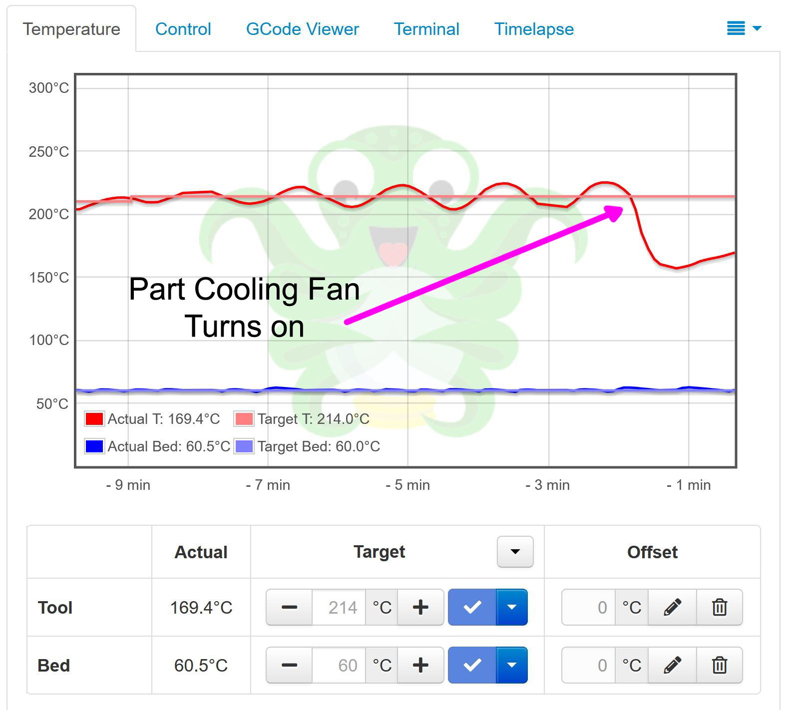
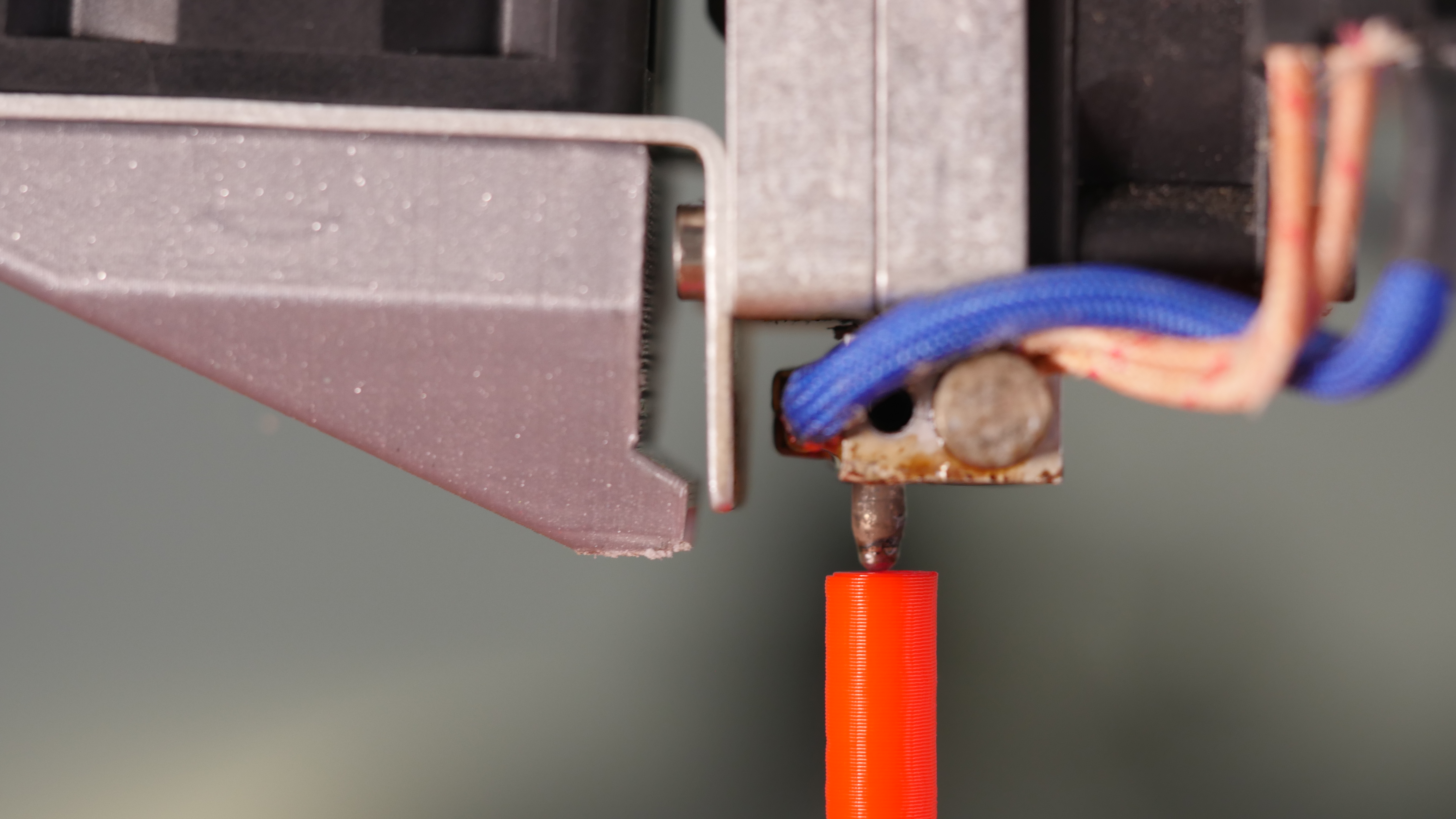
This is getting goofy, we want part cooling but we also do not want to chill the extruder. The Adafruit model does a fairly good job cooling the printed part, but it does unfortunately also cools down the extruder thermocouple. The shroud is also only attached by a single screw and it will likely move or vibrate loose. We need to get back to basics and see how this extruder looks with no part cooling and devise something to get around the issues we're seeing. How does the extruder behave without the part cooling fan?The extruder by itself consists of a two part split plate with holes going through for cooling. The heater is the fairly-standard 24 V cartridge style with a thermocouple bolted to the outside. It does not make great contact, as what appears to be the measuring point is fairly far away from the contact bolt. The stock cooling fan has a small shroud blocking airflow from hitting the thermocouple directly. We know that the hot end does get hot and the heat break works well as the section above barely changes from ambient. We also know that we're likely a bit power limited on the hot end, as the power is delivered over a flat flex cable with maybe 1A total available. 24W is plenty but not enough if a blower is actively cooling it down. Do we actually need a circular blower assembly cooling all sides?
This seems like it's been solved on other printers, and I've never seen an orbiting part cooler on a production printer. How do the pros do it? 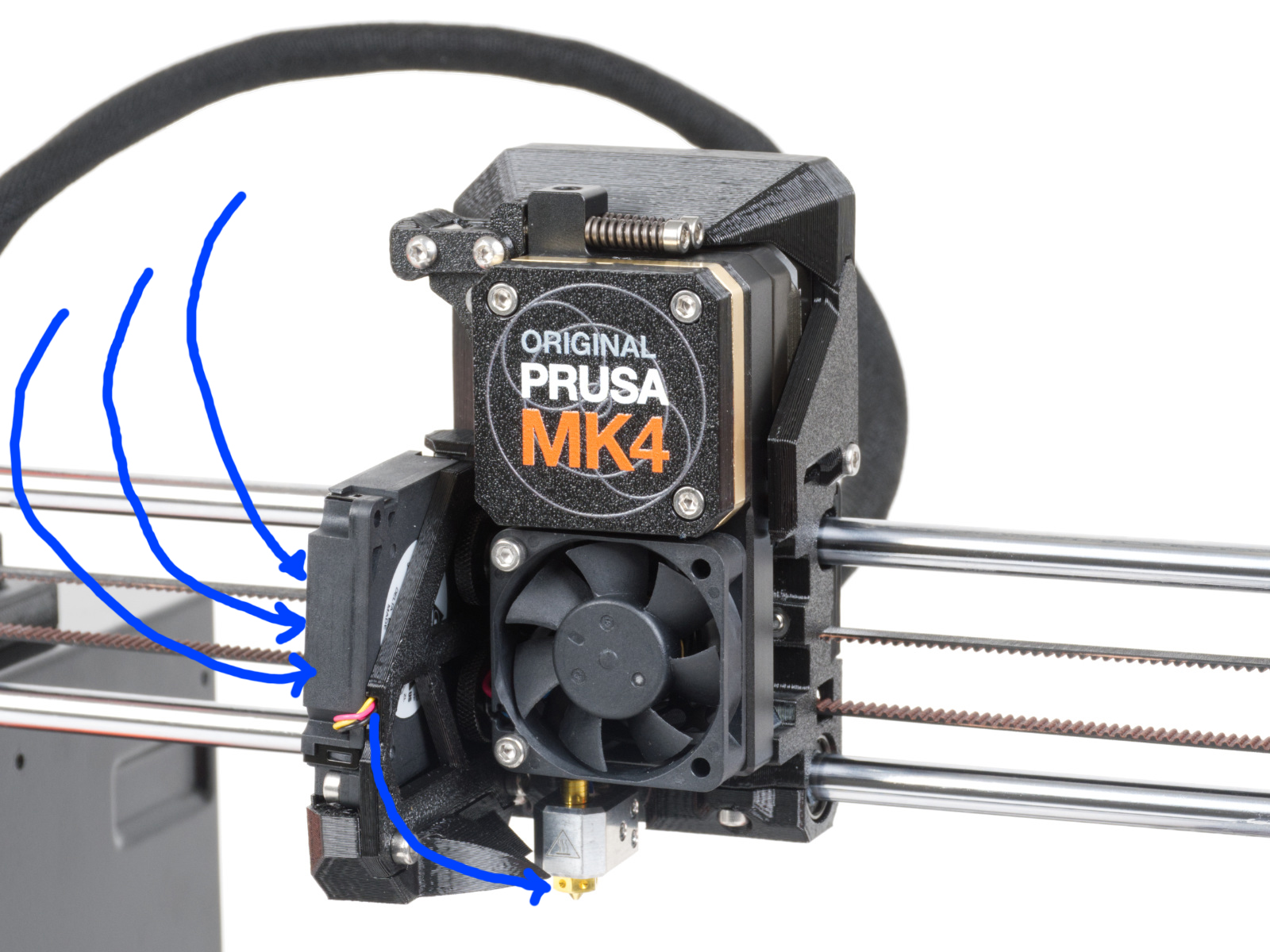
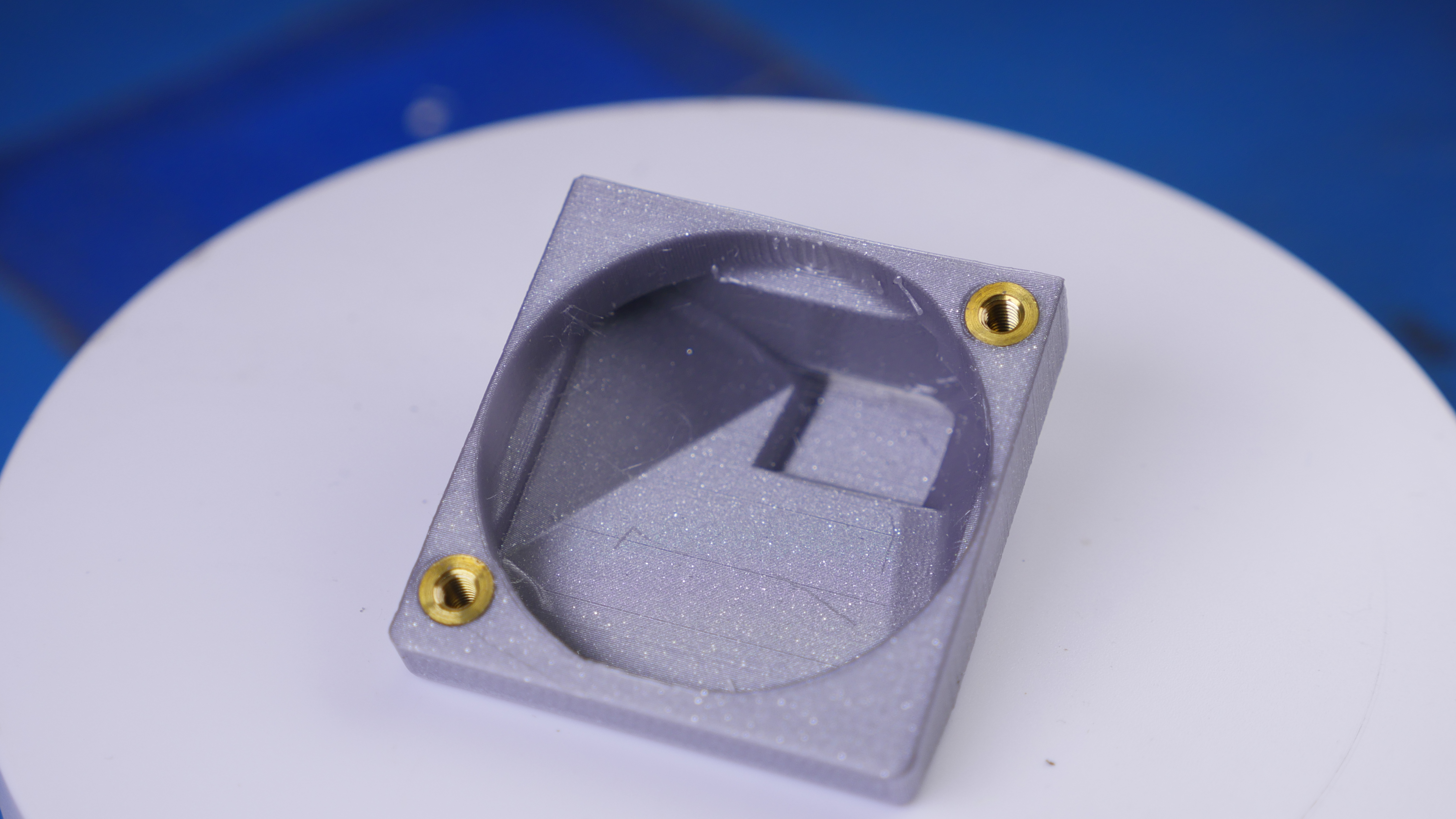
Prusa Style Blower for Series 1The amazon 12 V blower is cheap, but I'd like to find something with an actual part number, such that someone in the future can find something that's an exact match. Working off the amazon blower dimensions. We notice from the photo above that the blower is really aiming a small stream right next to the extrusion output and only that spot. I came up with this, a low form factor air guide that blows almost directly on the nozzle output but not on the hot end directly. This design allows me to still use the stock hot-end block without any significant modifications. 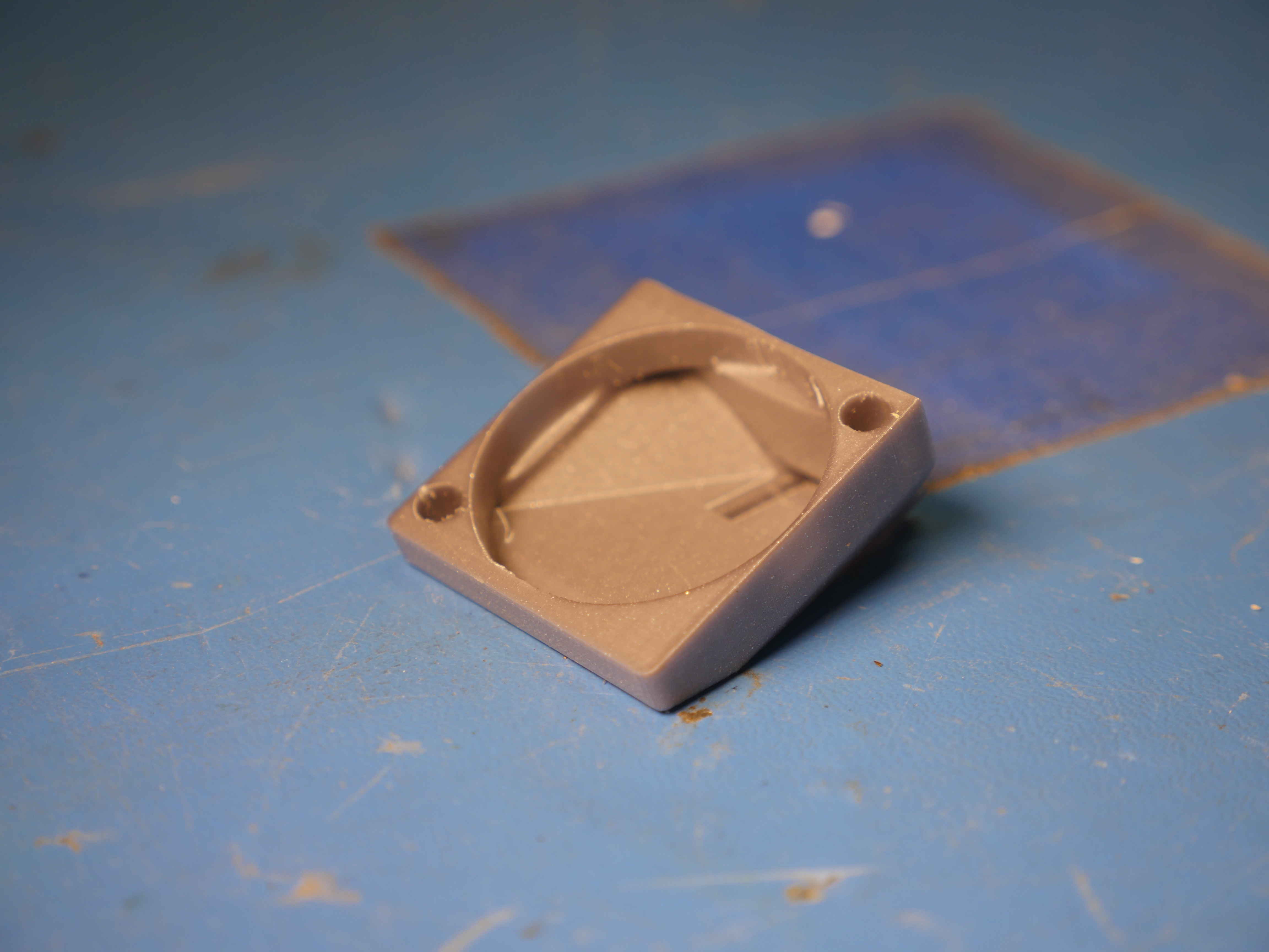
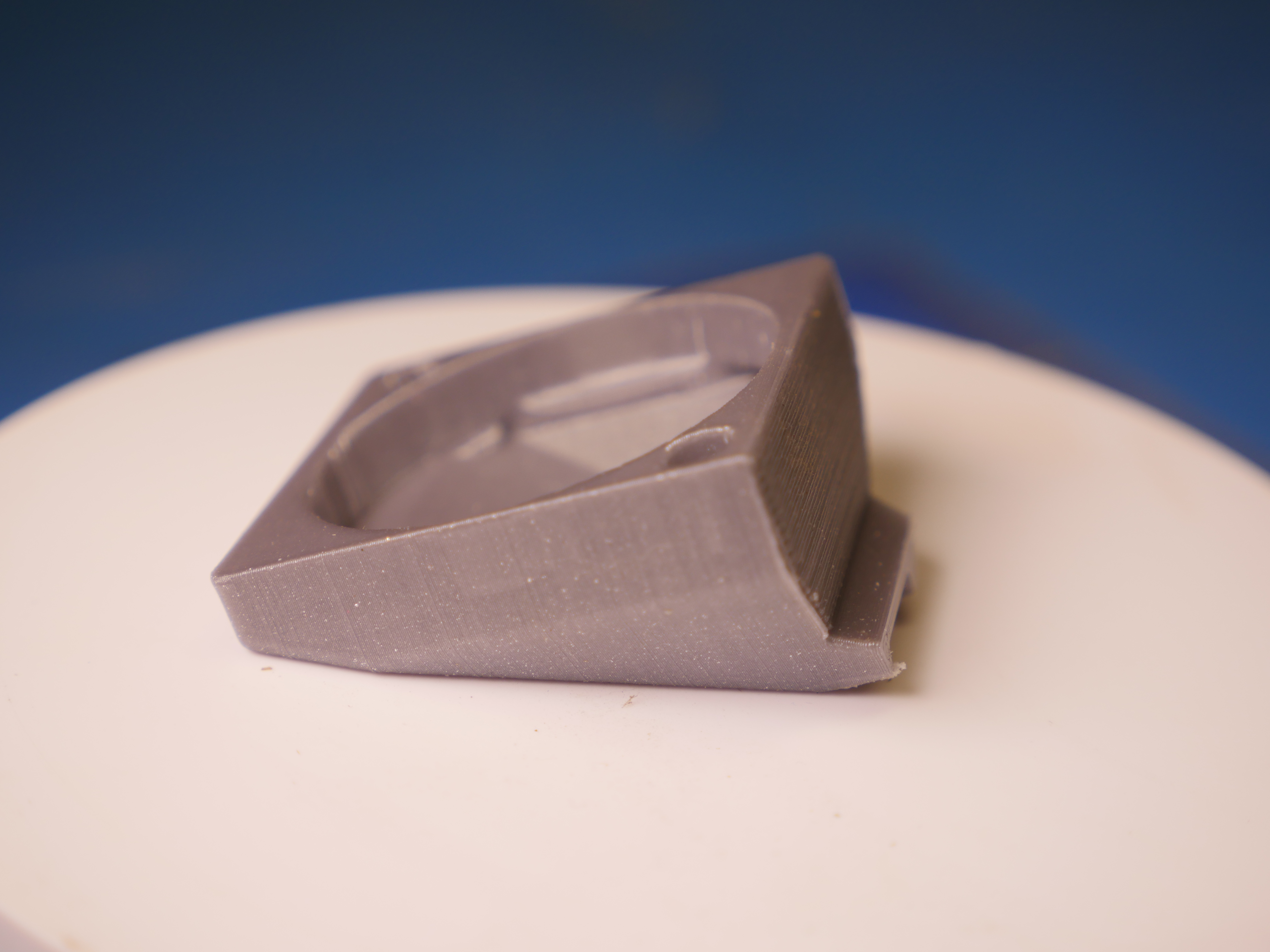
Using the tried and true 'heat up a thermal insert on the end of a bolt' technique, I added two M3 brass thermal inserts. Everything fit really well. This was my first foray with prusament and it is also remarkably nice to print with. 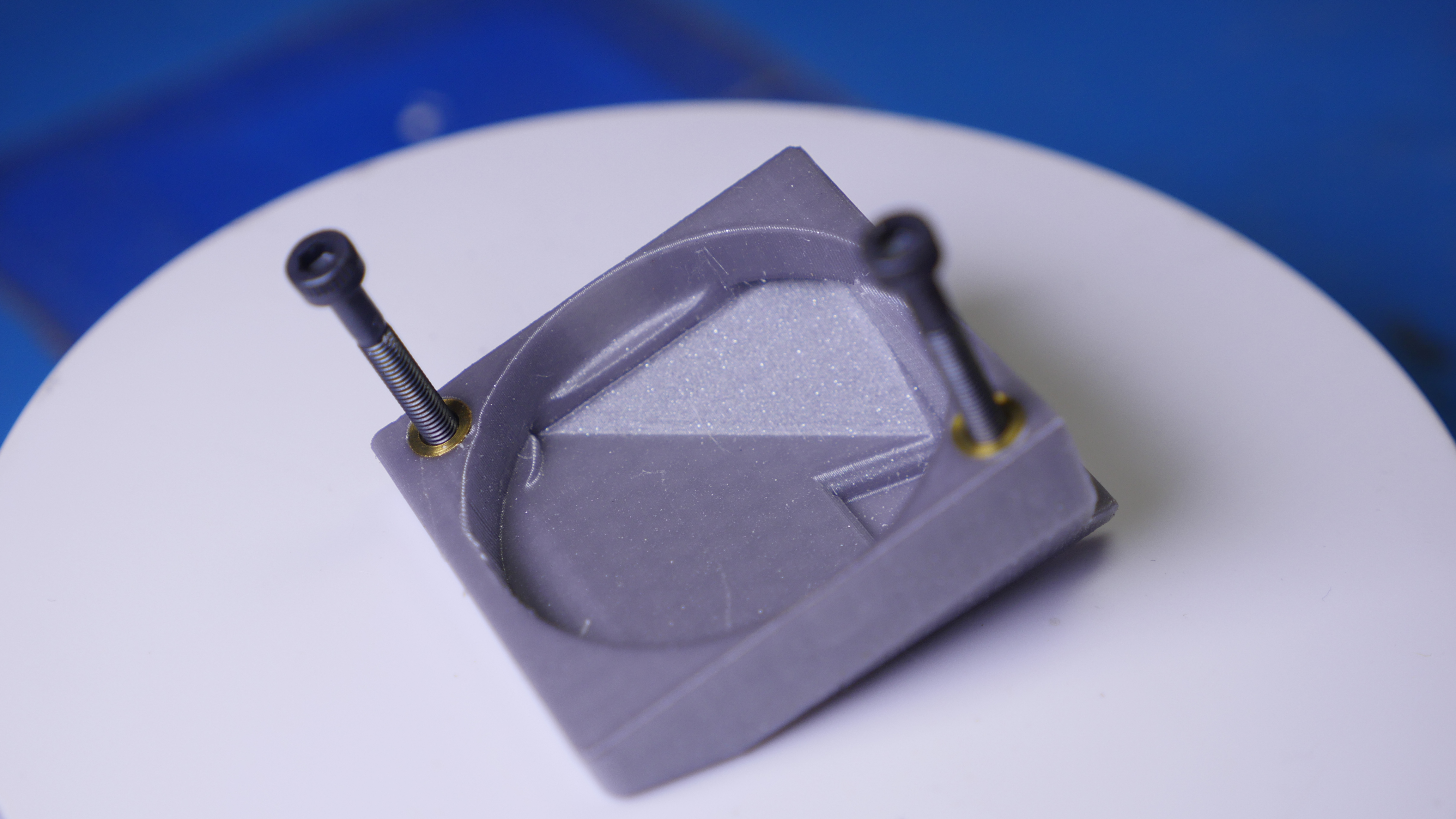
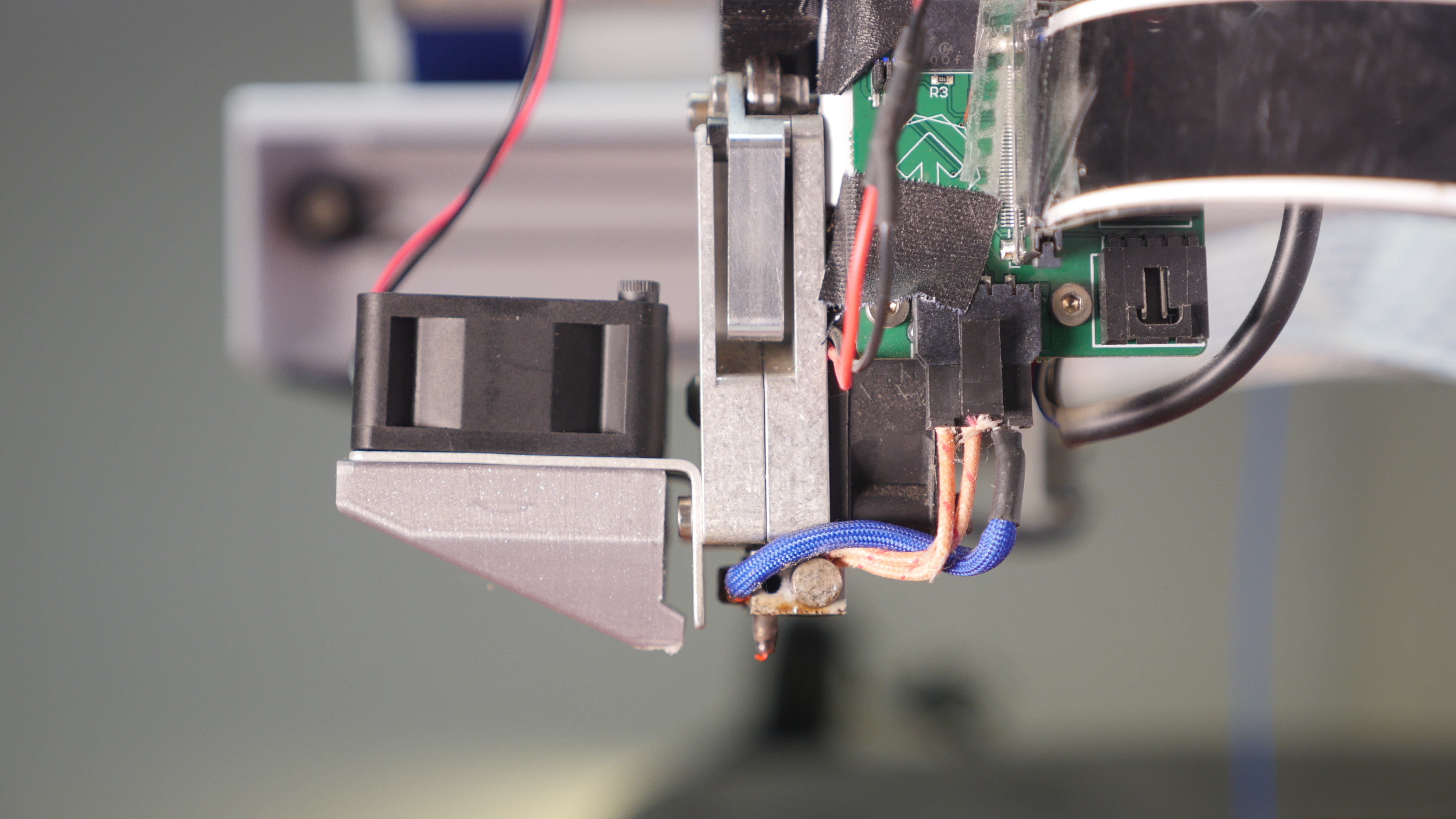
Installation, along with a newer fan was also fairly straightforward. Given that the new fan is taller than the stock fan, i used slightly longer M3 hex head bolts. The side shot below shows how the stock plate that blocks the thermistor 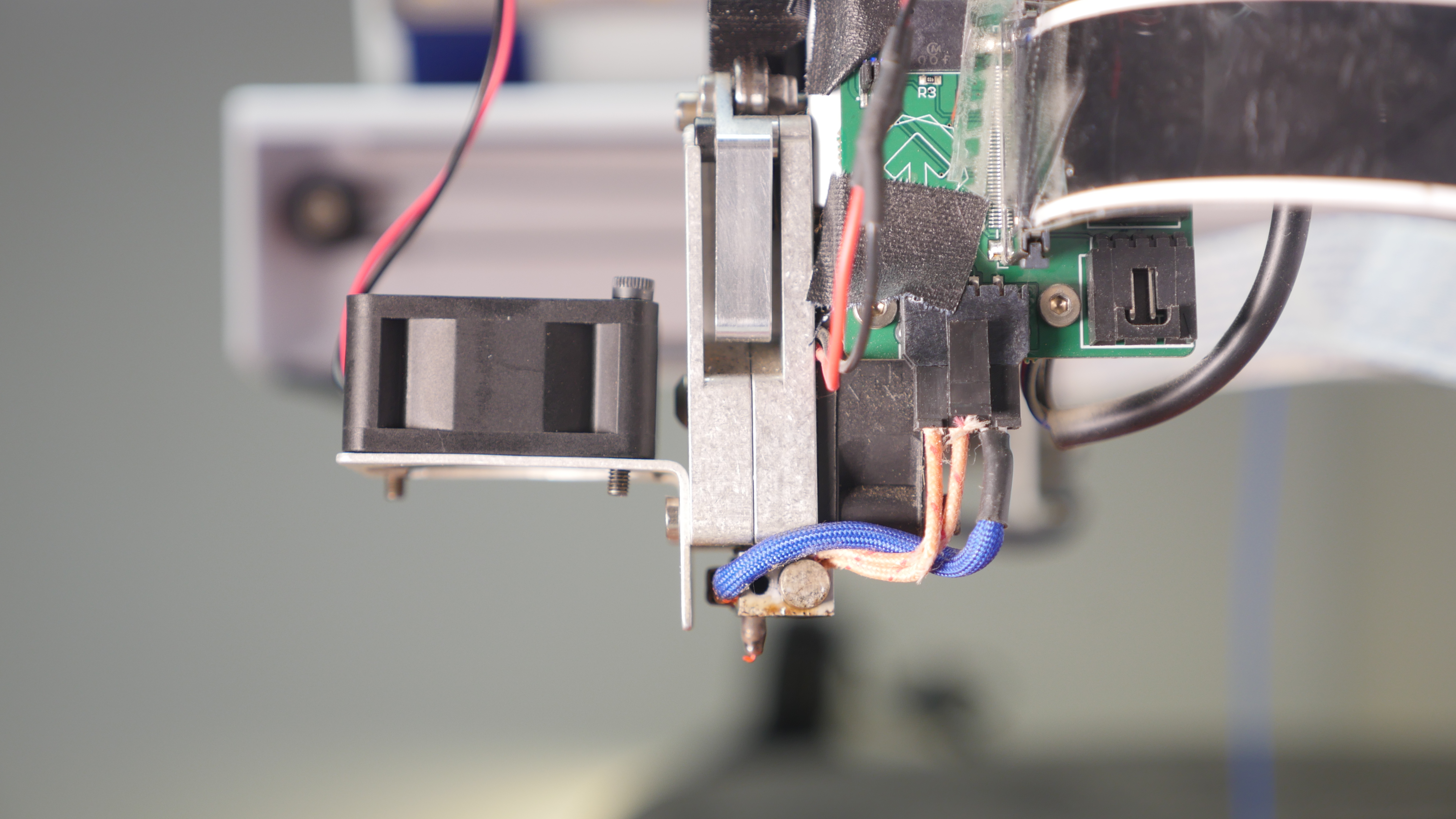
Next up we can see how well it performed with the same 'tower test' from earlier. These were taken with my new macro lens and it is absurd how well this performed. 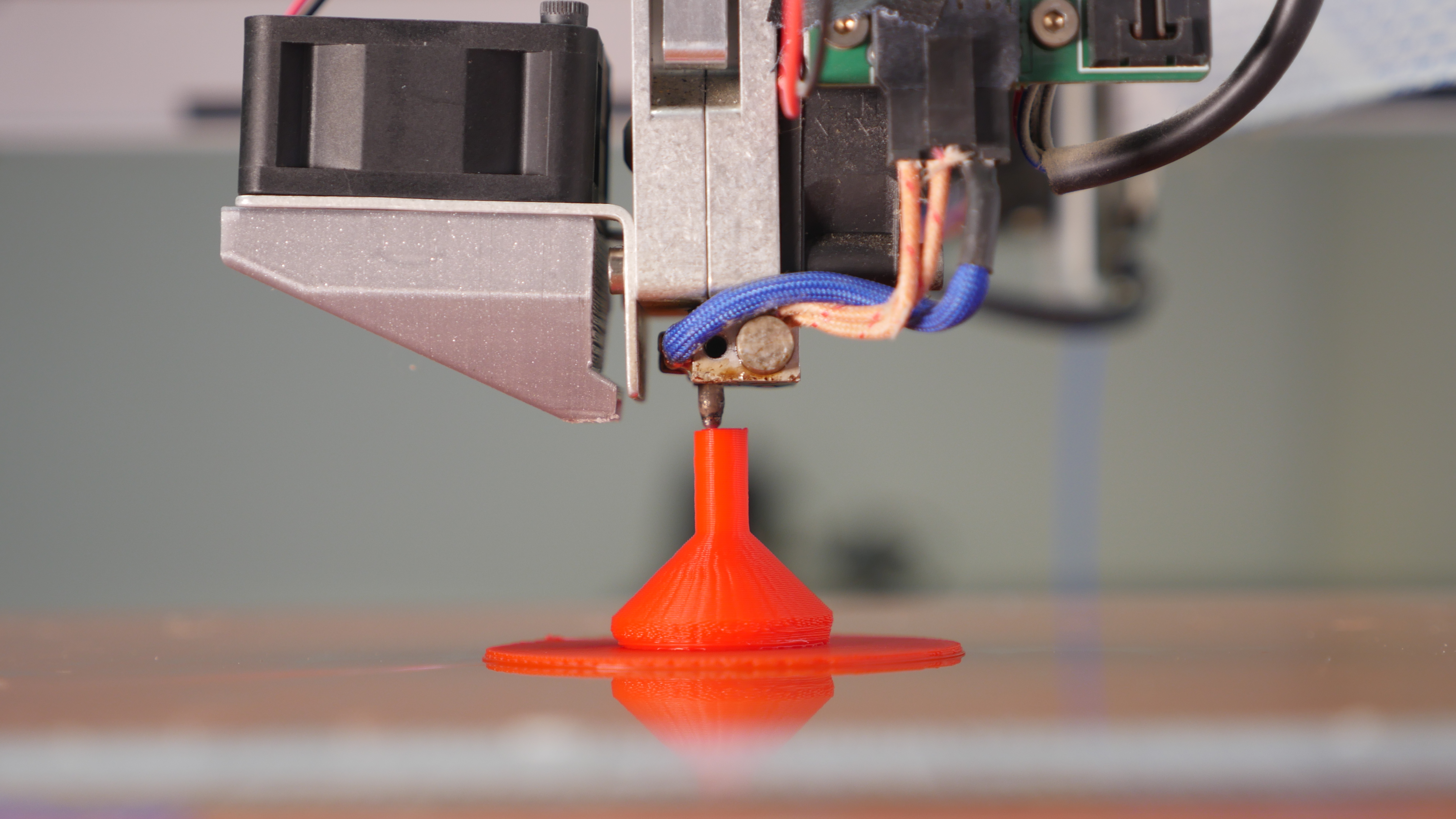
It is remarkable how much of an effect this has on the print quality, especially for this edge-case. Just look at this thin tower print and how much better it is versus what we started out with! Shown below are some macro shots of the extrusion tower test. This test is a fairly simple stress test but it really shows how thermal buildup can affect the print quality.
The print working splendidly below: 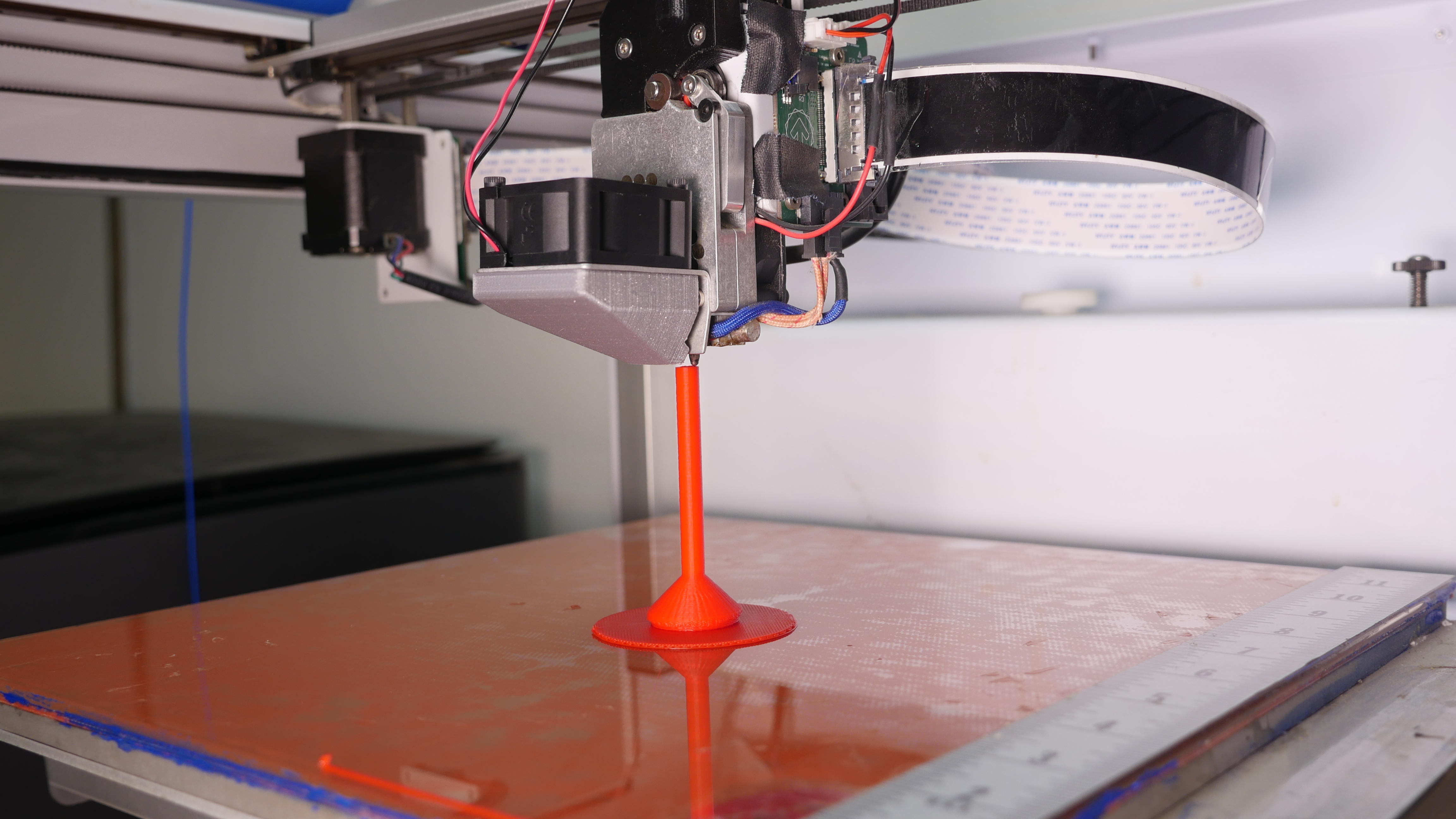
Before and AfterHere's how much the change in the blower effects the print quality. Shown is the new blower (right) and the stock blower (left). The heat block was nudged up for the second shot due to the stock set-screw not quite gripping the nozzle and sliding down. Adding a magnetic build plateWith the advent of really large magnetic build platforms, we can now get around having to print on glass, or making bed adhesion goo's. I used this kit [link]. Adding this to the base was initially pretty straightforward. I cranked the build plate to 60C and let it thermally soak for a bit. After re-cleaning the surface i applied the adhesive magnetic sheet, as shown below. Yeah that didn't work as planned. While the adhesive magnetic sheet probably sticks really well to a metal sheet, it did not adhere to glass well at all. I didn't get a chance to film this bit but I ended up pulling the adhesive sheet off and then using DP125 3M 2 part adhesive to the glass surface using a spatula. This was a bit terrible, as the adhesive needs to be spread evenly so that the surface is not lumpy. After trying to spread it as flat as possible, with the bed warm, I placed the magnetic sheet back on the surface. There was a lot of poking and prodding to squish the magnetic sheet flat. I used the printer head as a leveling tool, checking the gap and squishing the epoxy'd in place magnetic sheet into submission. 24 hours later, with the epoxy cured, and the new build sheet installed it was time to do some test printing and dial in this printer further. The new build sheet has a magnetically attached gold sheet as well as a 'carbon fiber' black sheet which is really great for brightly colored filament contrasting. For glass-bed prints I almost always ended up with a raft to aide in adhesion, and the newer PEI magnetic print platform has significantly higher adhesion, and as such later prints can get away without having to waste print time with a raft. Shown below is a 10" wide part, the fuzzing in the back corner is just an artifact of the time lapse associated head movements. Cura Printer ProfileIf you end up in the condition that you found a Type A Machines Series 1 and want to slice and print with Cura, here's a link to a working configuration profile [link] Concluding Thoughts
Using open source hardware also makes future upgrades easier. I'm presently running into limitations of the 8 bit stepper controller board, while 32 bit variants are now common.
Have you noticed that there are no
advertisements or ridiculous pop ups?
|

Post your comments! |
|
Comment Box loading
|