Dane.Kouttron
[09.02.22] Blue-Bot Upgrades: Vision and Hardware
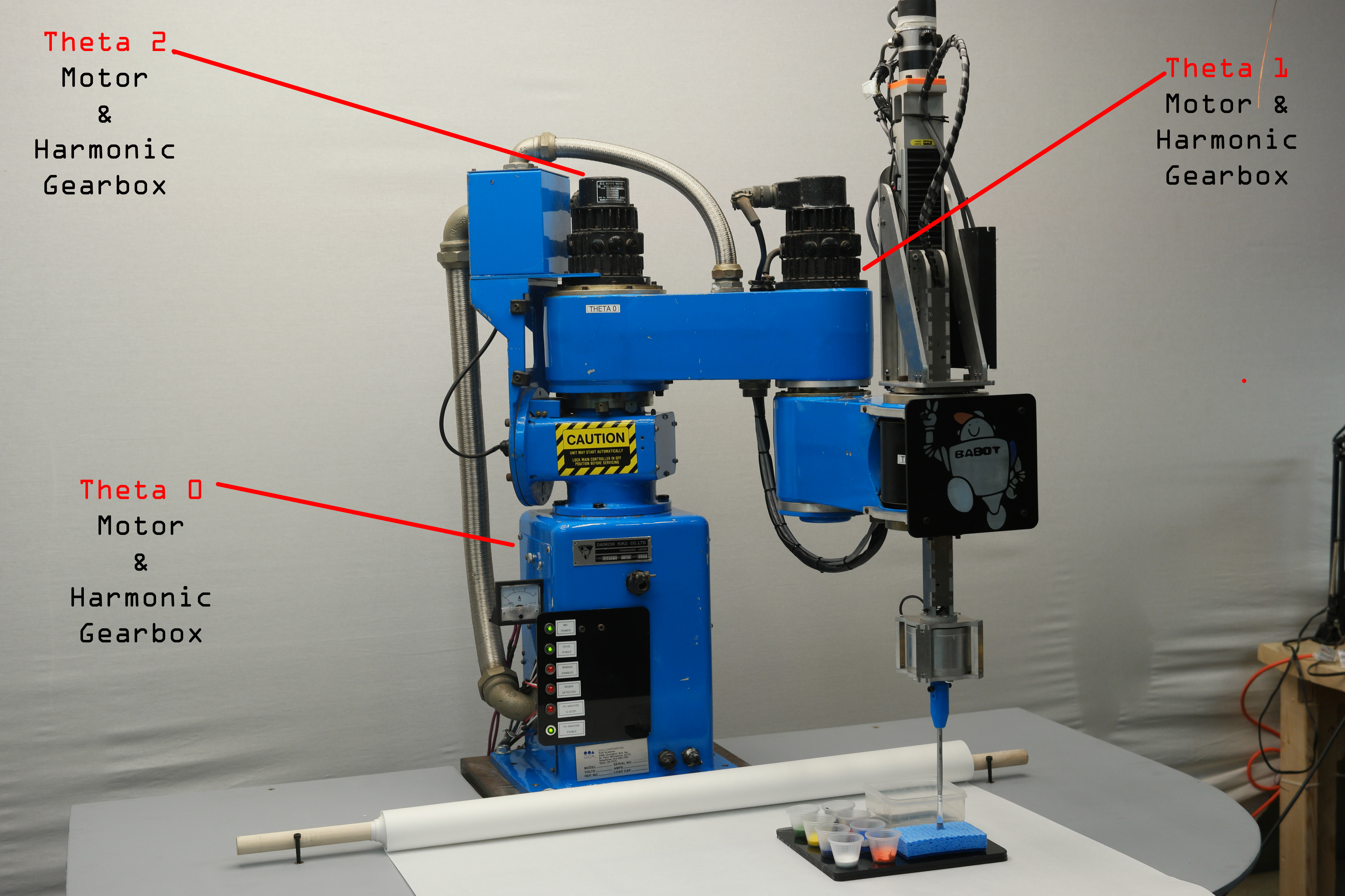
So here's a quick reminder of the layout of BABOT, three theta axes, each with a brushed dc motor and servo controller Adventures with waking up the monstrously large Blue SCARA robot of were quite good. Some software and hardware upgrades were implemented to increase performance, and they are listed here. |

| The mechanical issues: Tearing down the sad gearbox |
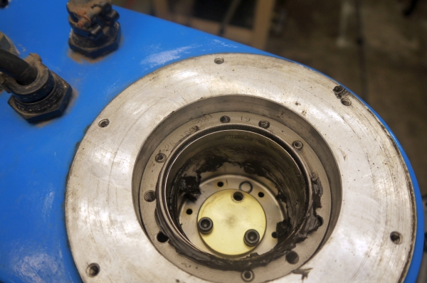
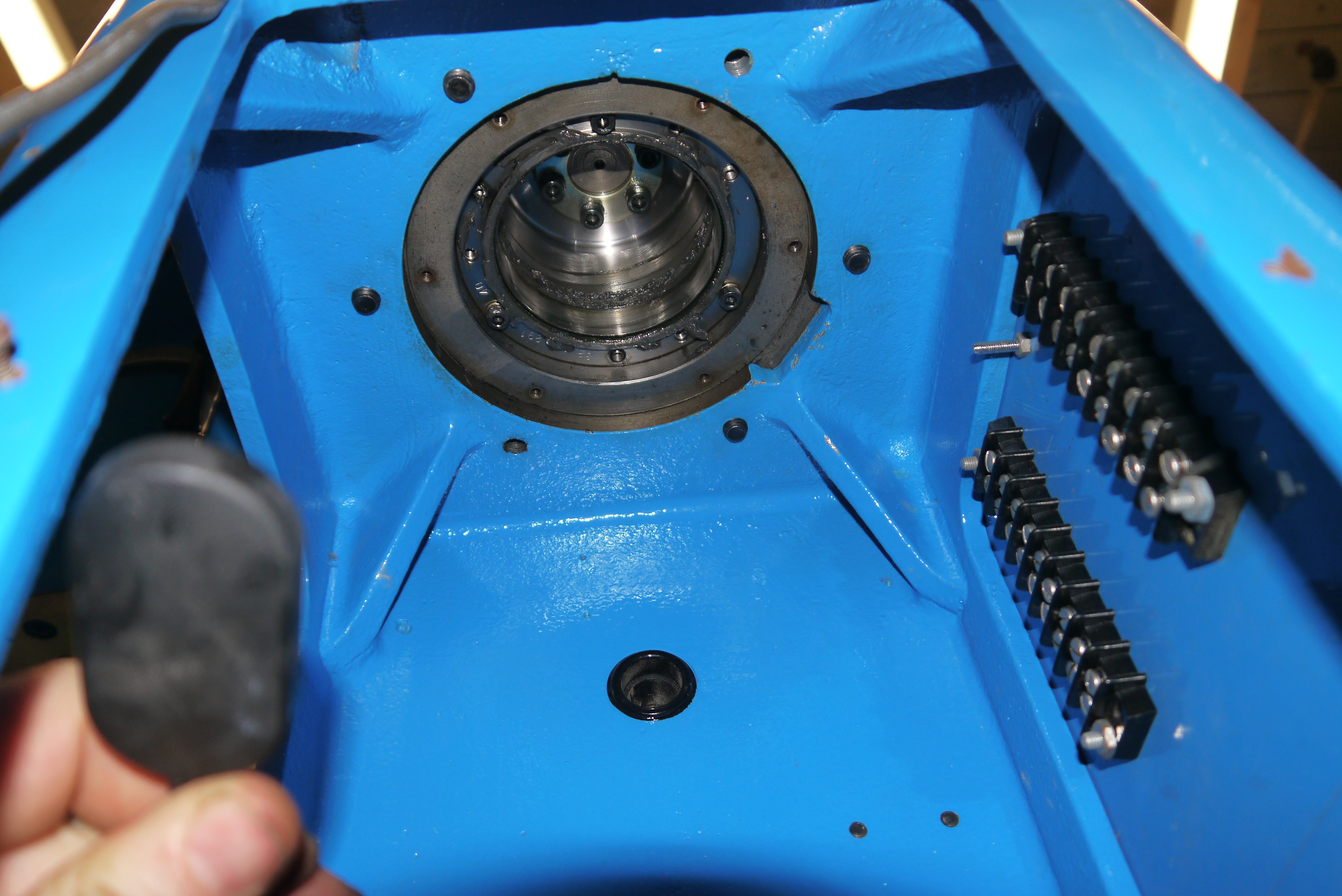
Here's
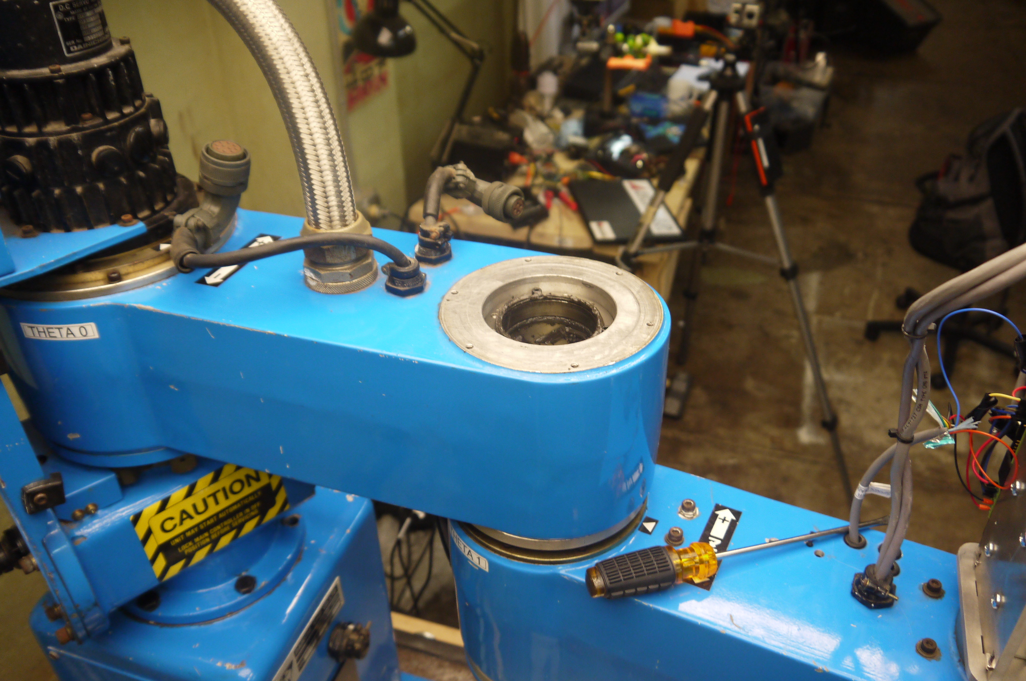
the theta-0 motor. Note the zip-ties are holding in
a cap for one of
the motor brushes. The motor assembly has a recessed
circular interface
such that it stays concentric with the robot 's
theta 0 gearbox. Eight
M3 screws hold this whole beast in place. Note there
is no gearing or
anything inside this assembly, its all big ol'
DC-Servo. The base has a
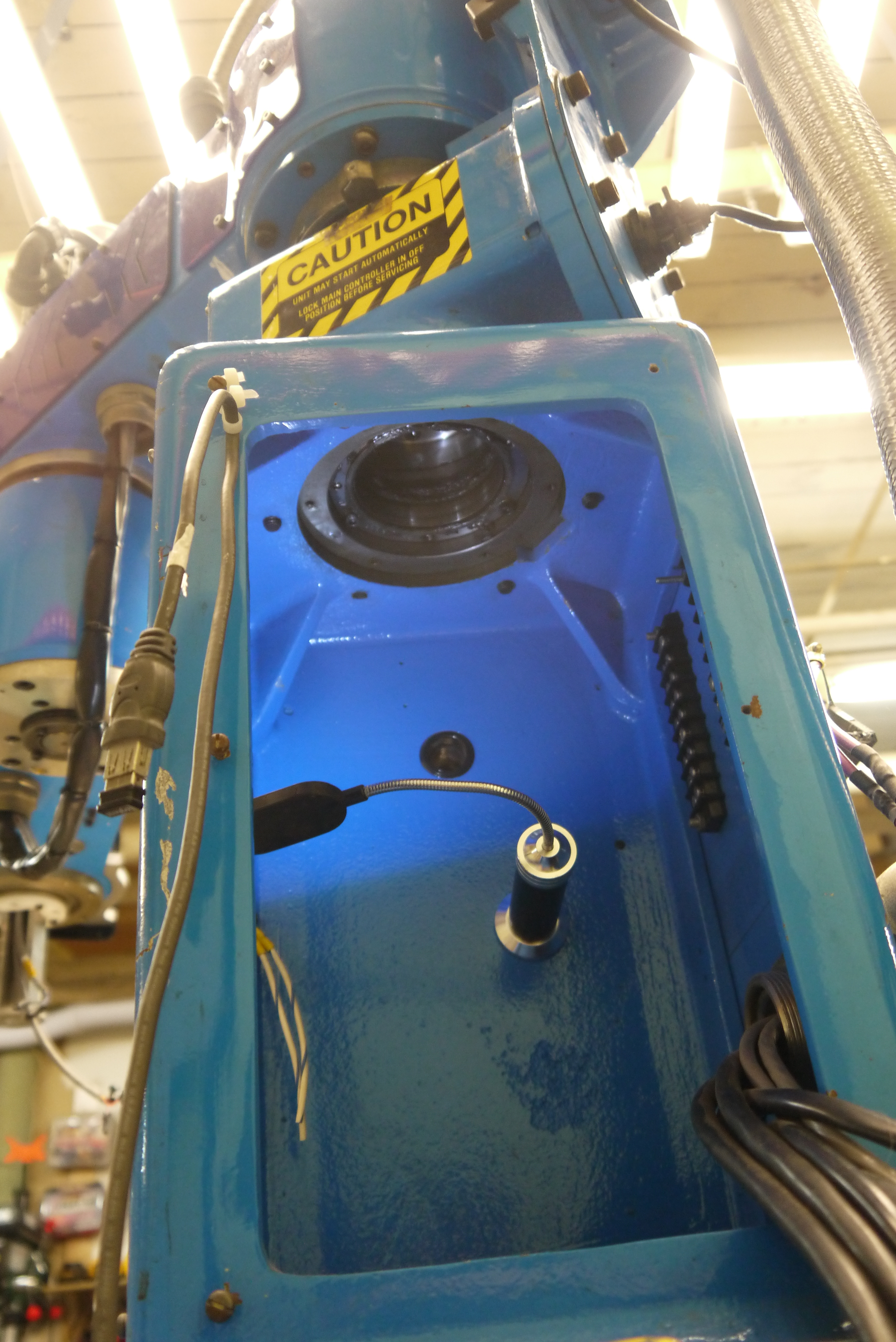
concentrically mounted optical encoder as well.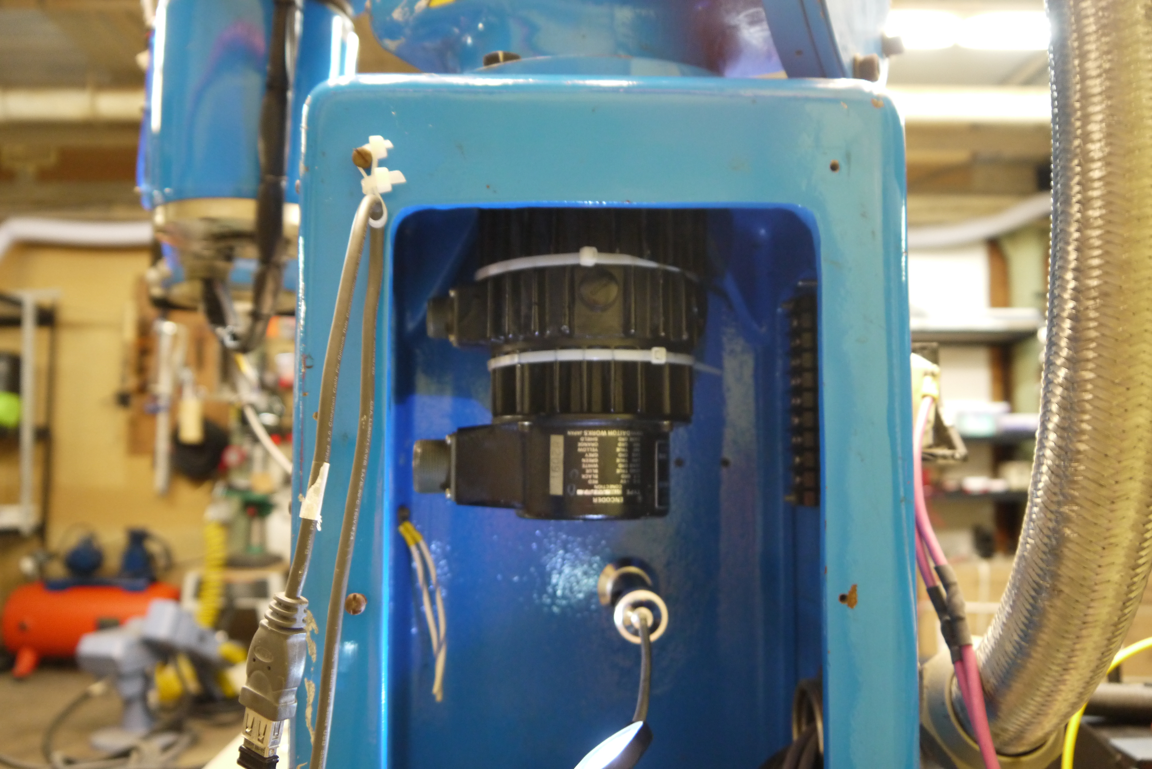 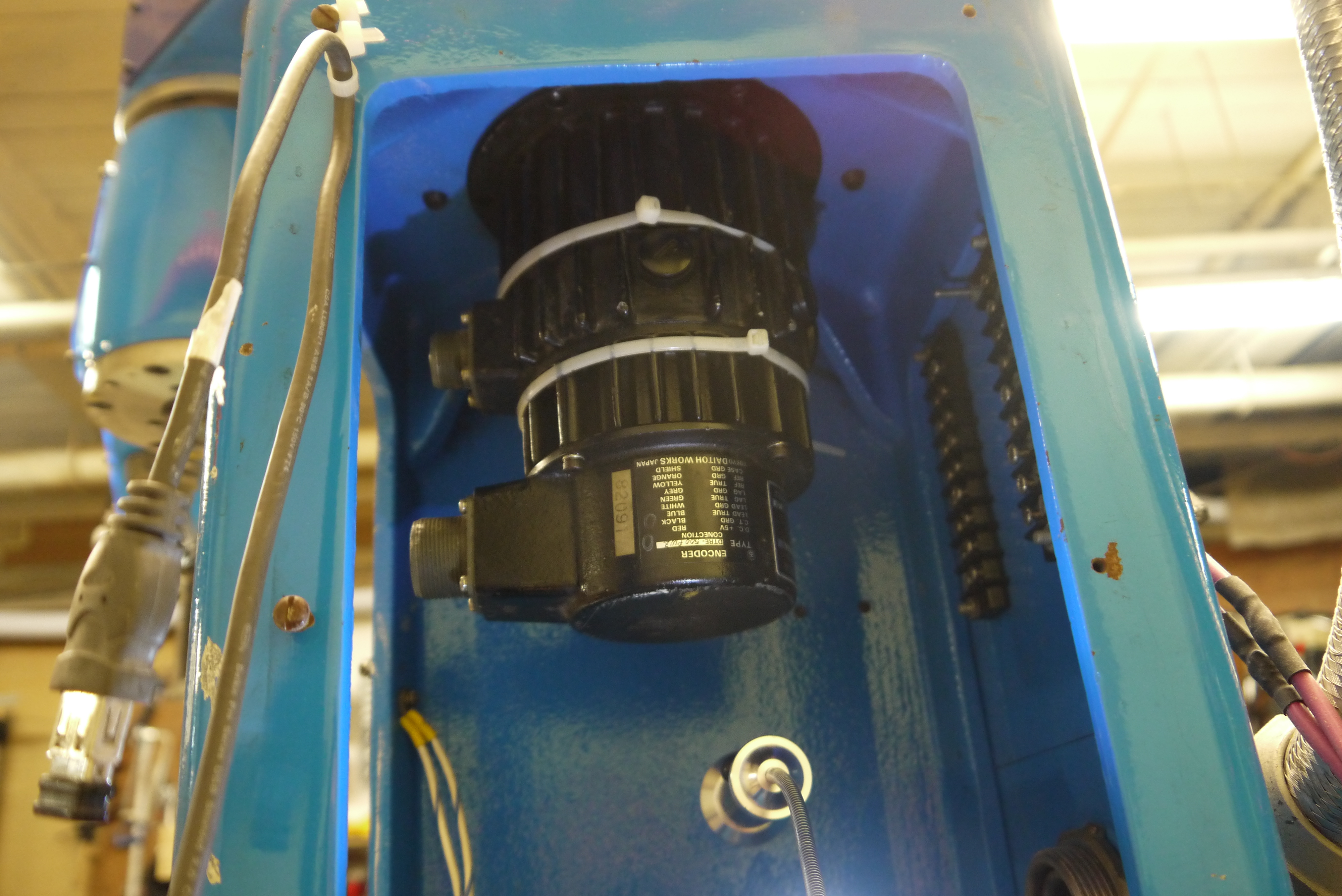 After removing the
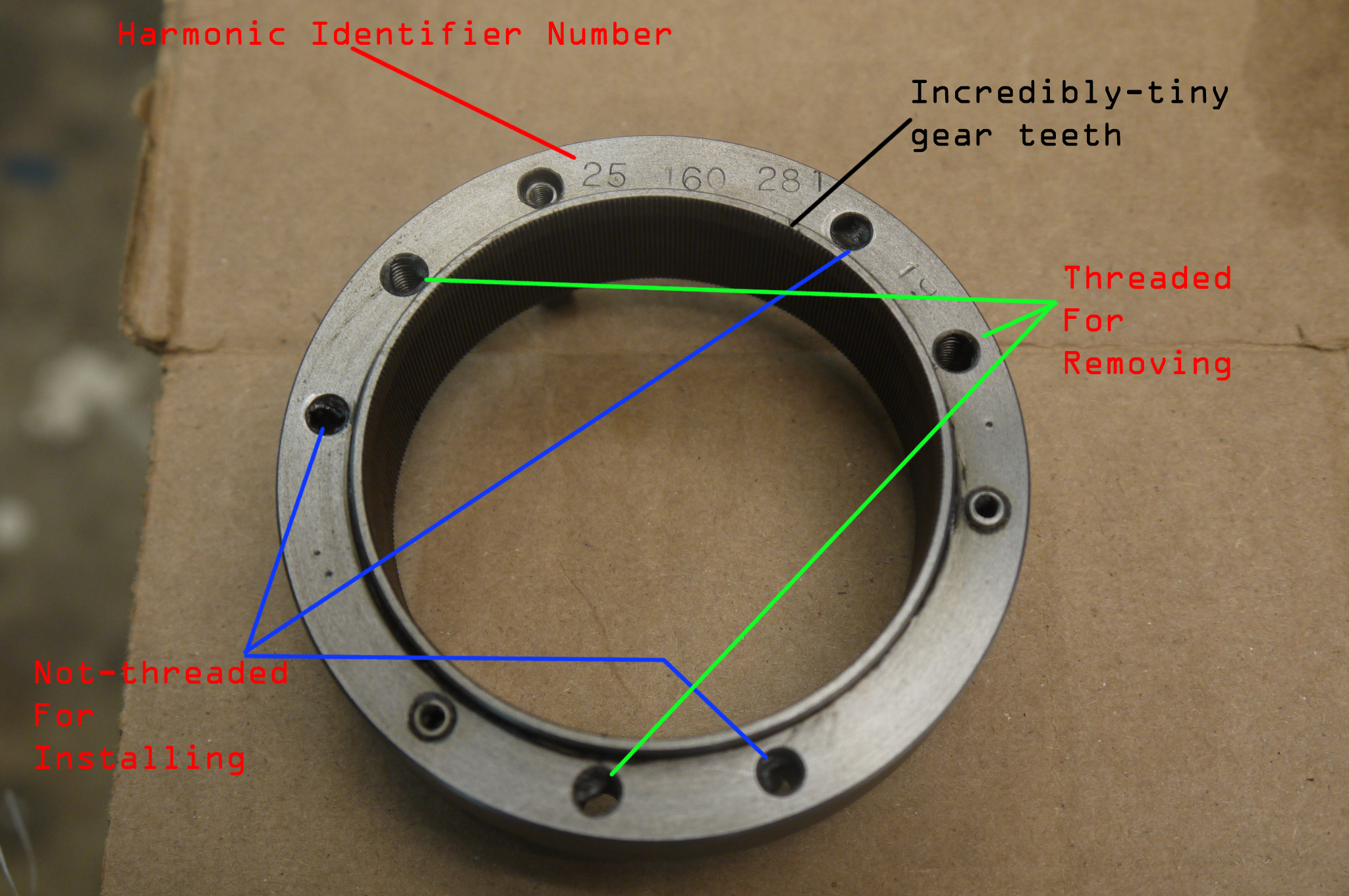
motor the first thing I noticed is the theta-0
harmonic drive is frigging huge
in comparison to theta-1. Keep in mind the
disassembly is upside-down,
and inside the robot. Nominally i could have lifted
the whole robot up,
into the air and rotated it about, but that became
an increasingly
difficult option. So upside-down it is. I began by
using a 3/8 impact
driver to loosen the 6 M6 bolts that kept the
harmonic flexible spline
in place. Note you can kinda see the 'its sheared
apart' just from
looking underneath.
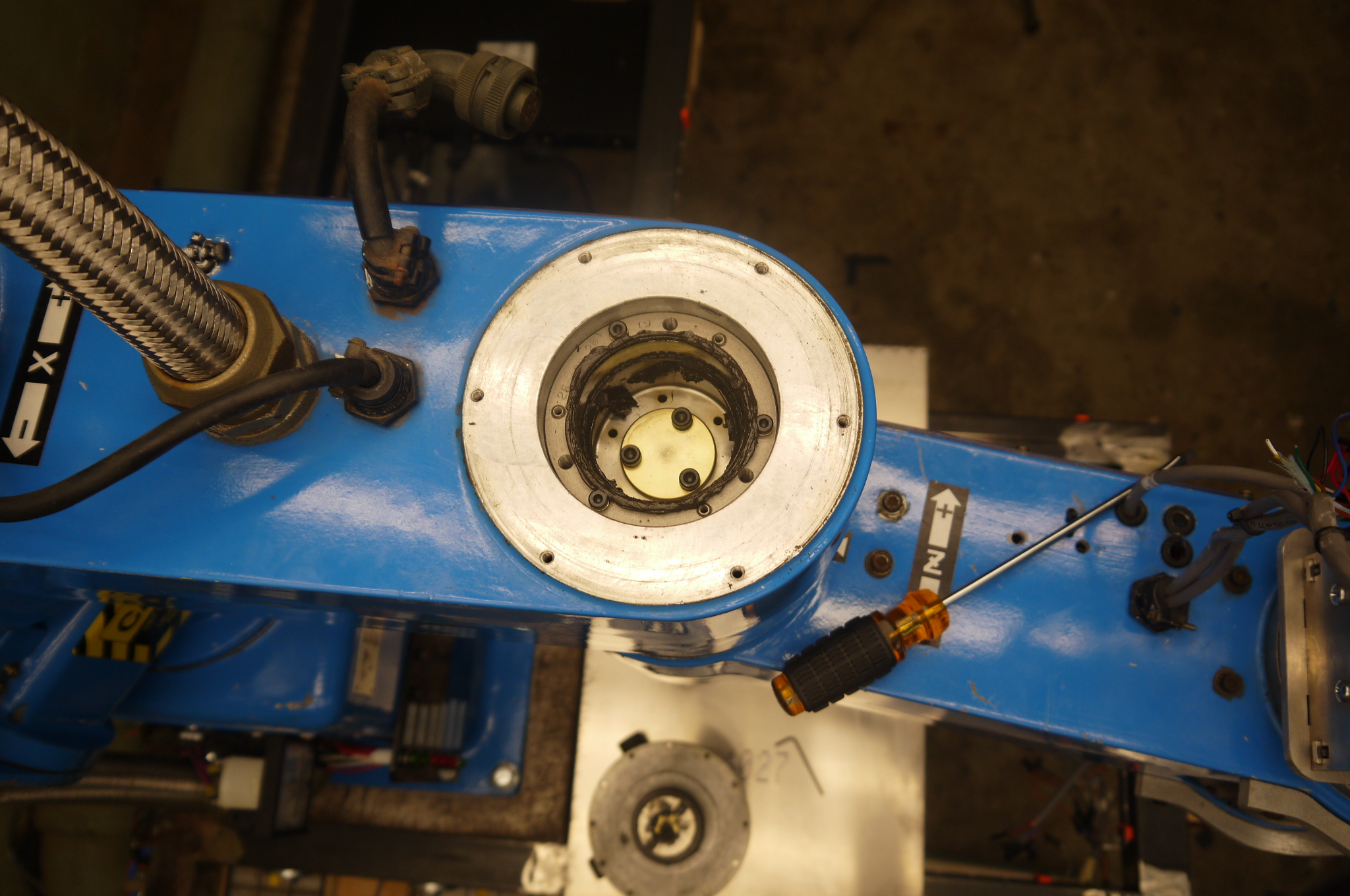
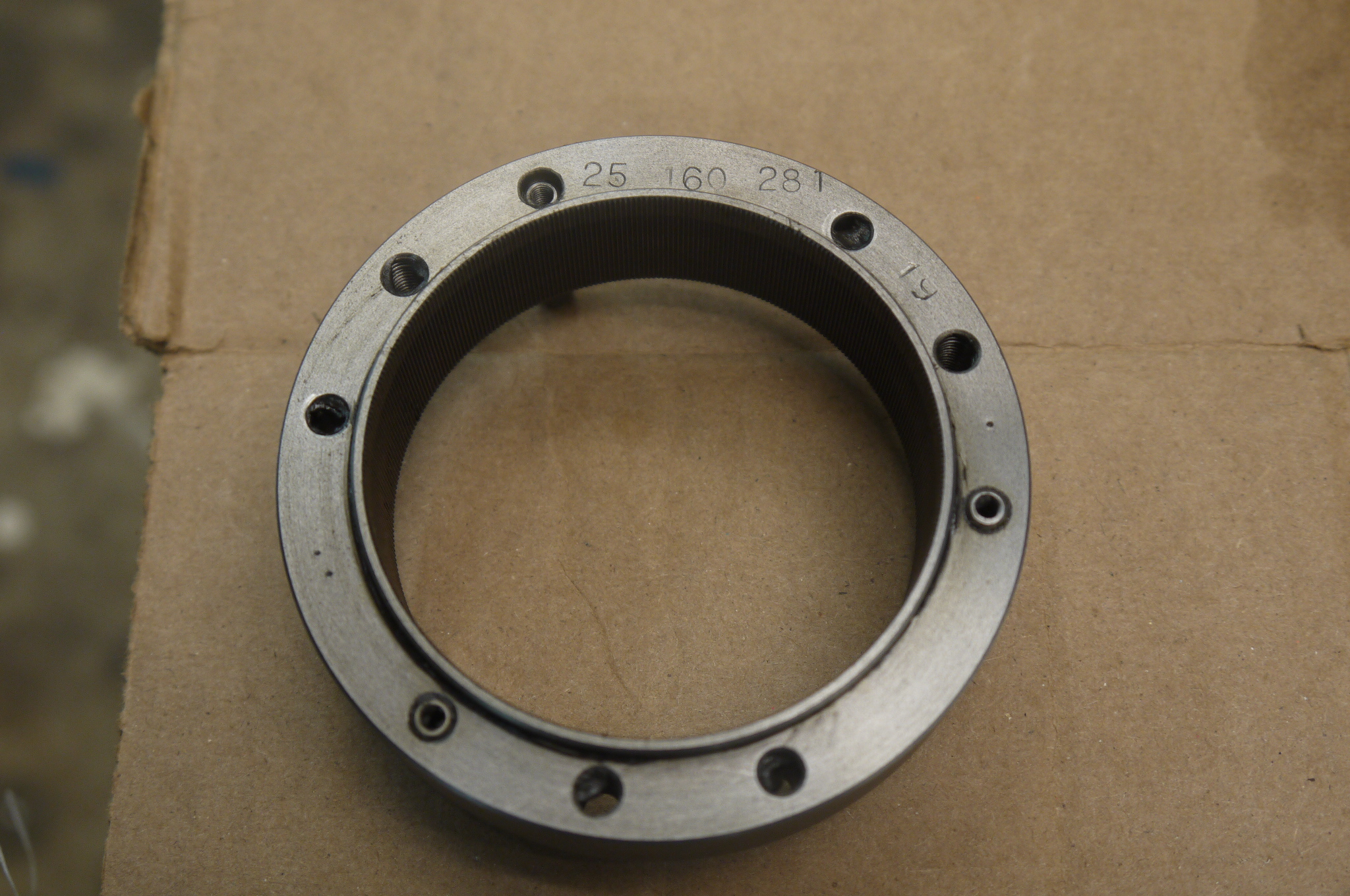
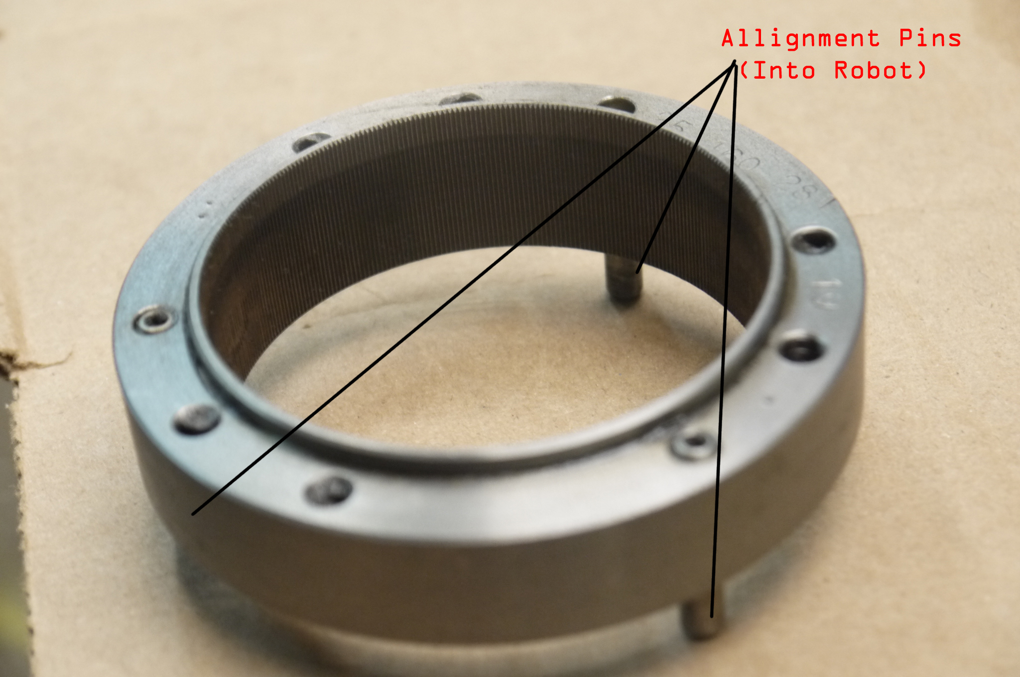
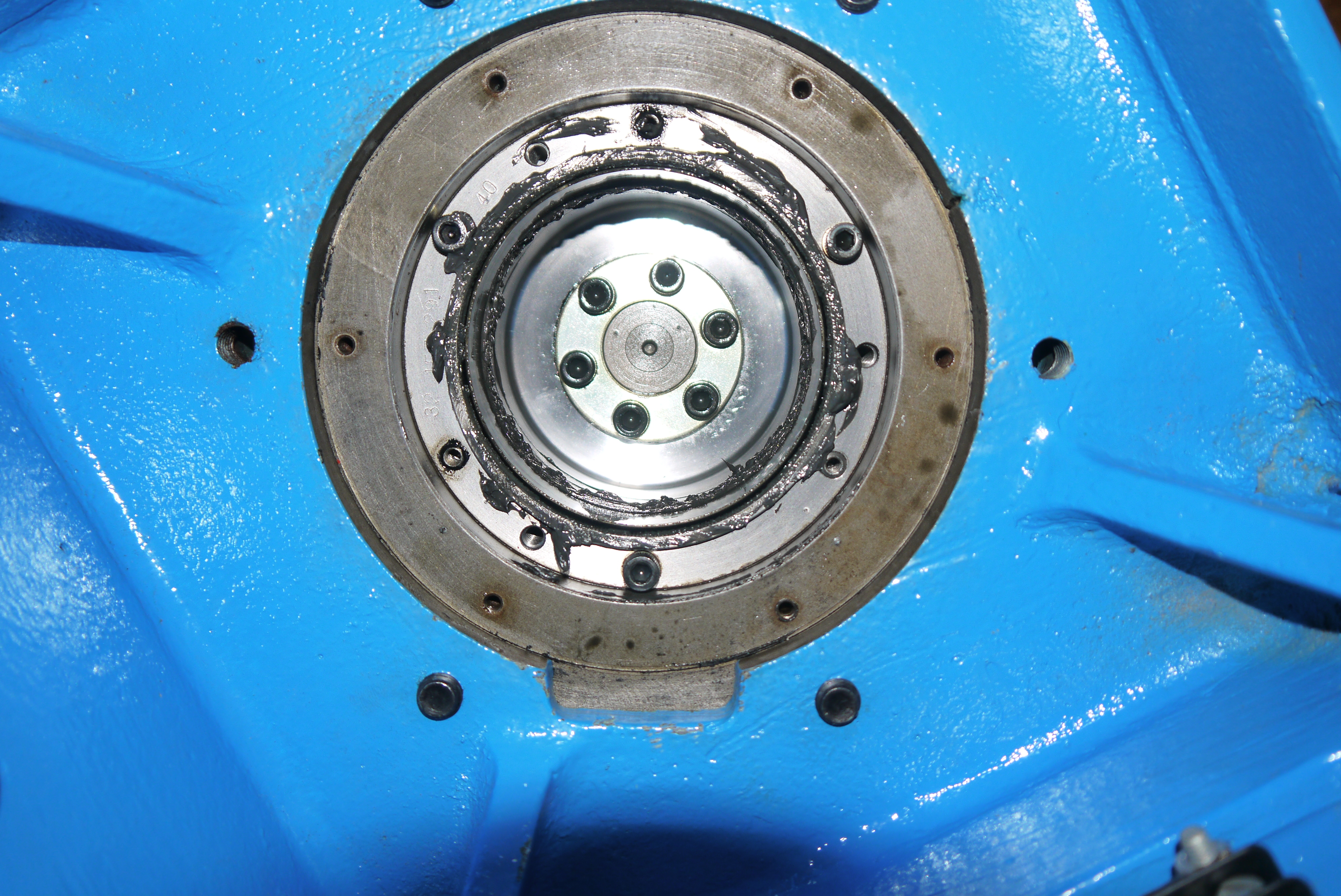
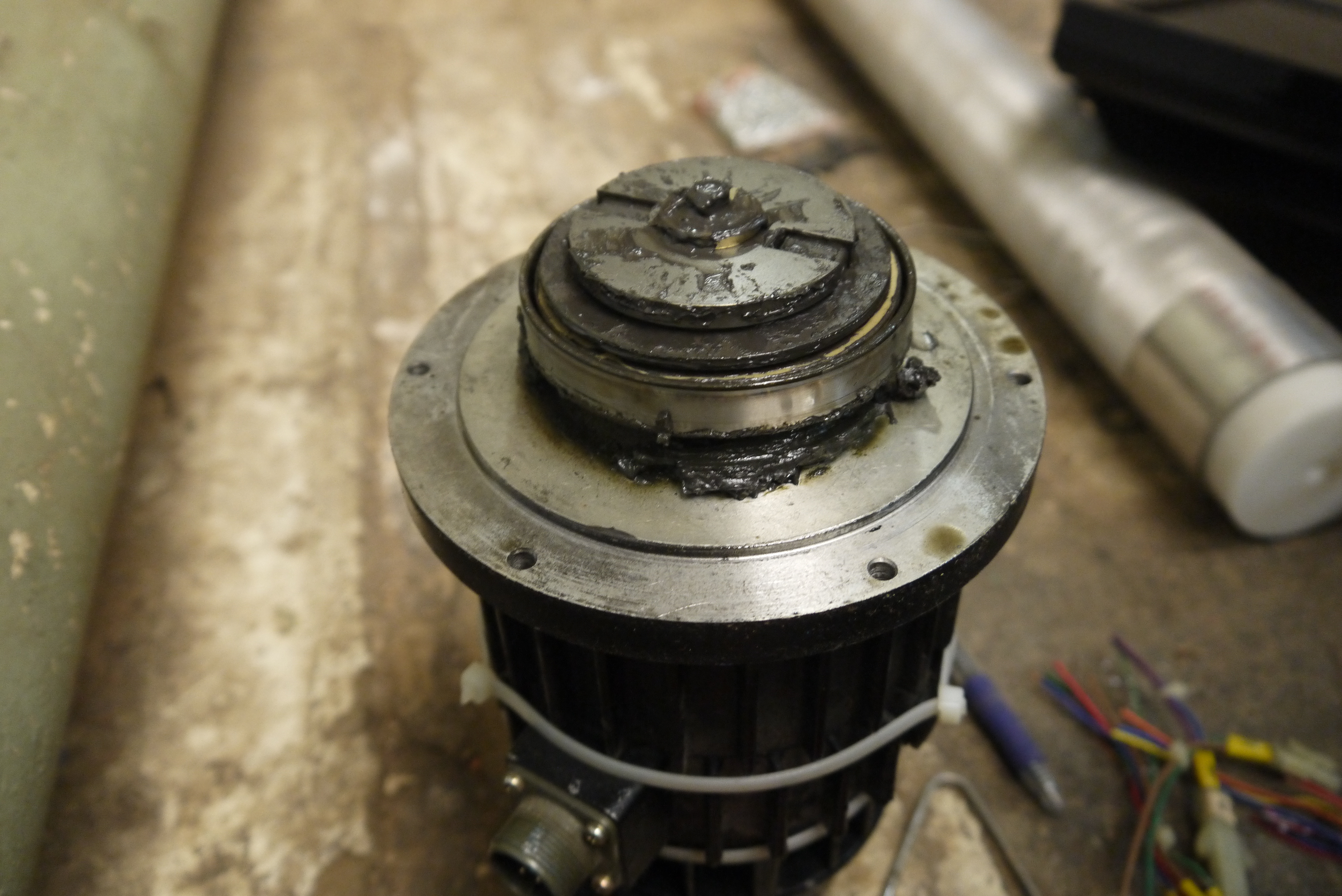
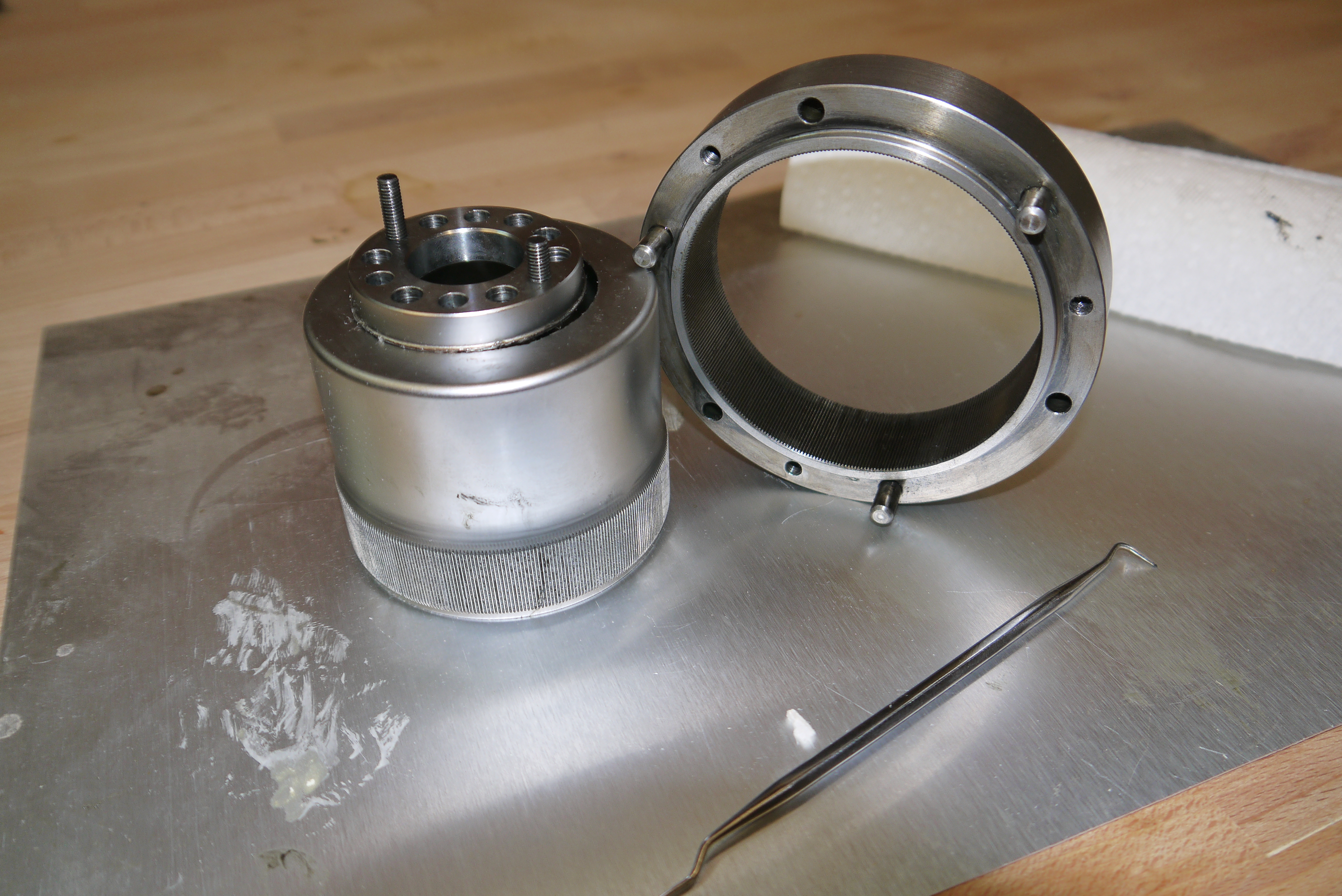
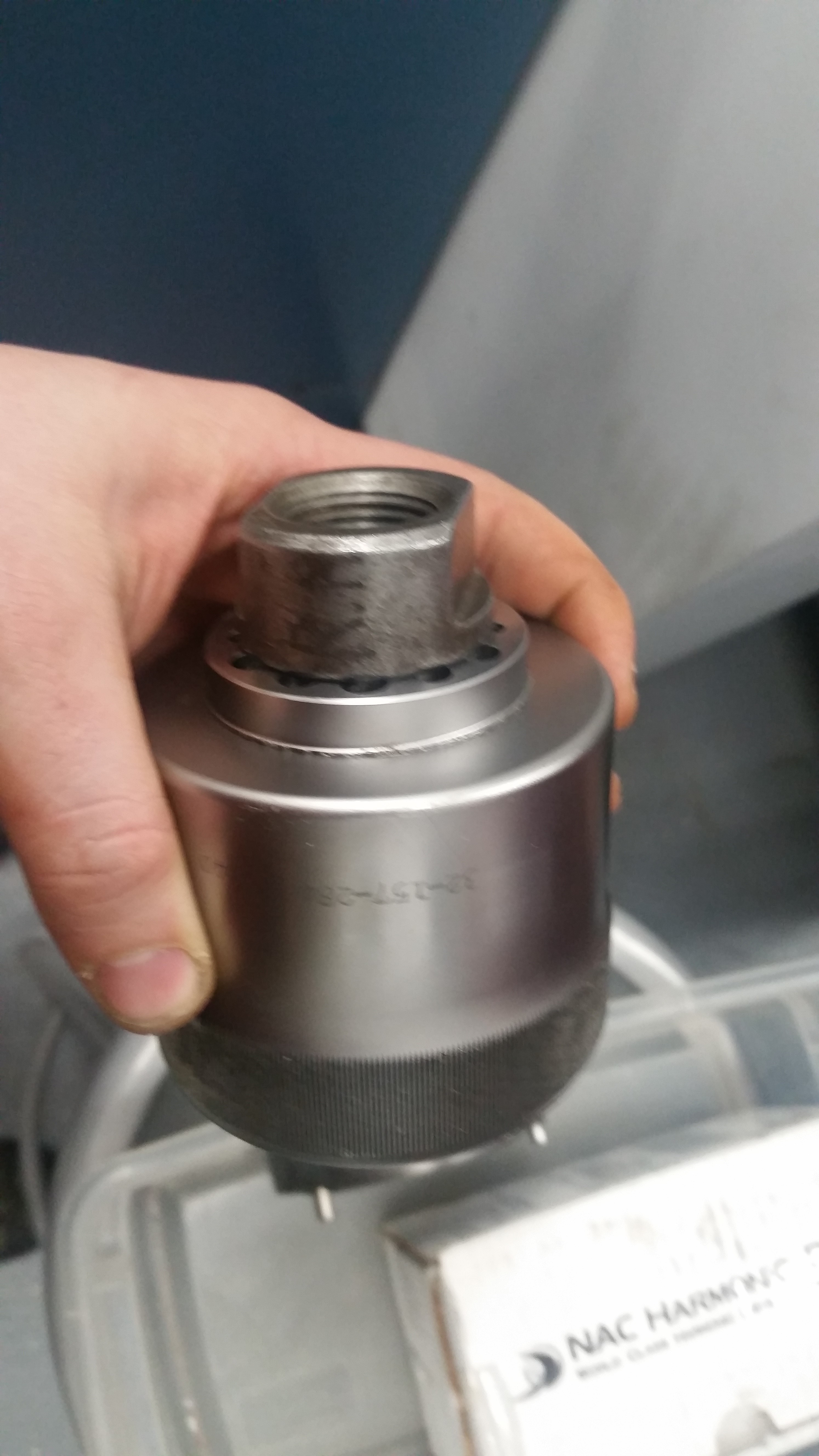
  Ok, better
photo of the sad harmonic gearbox. The
flexible spline is only held in place by the
burrs generated when it sheared.
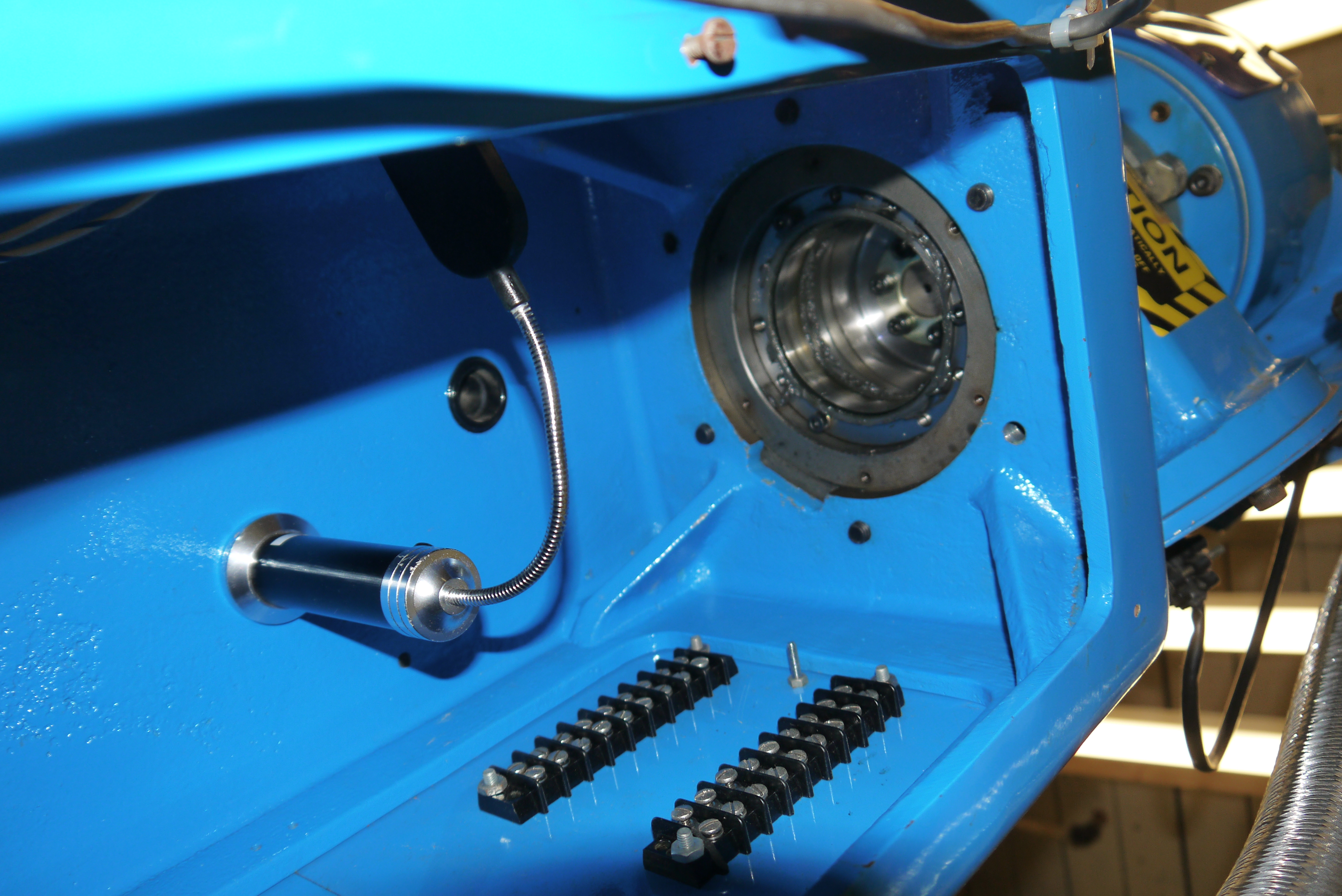
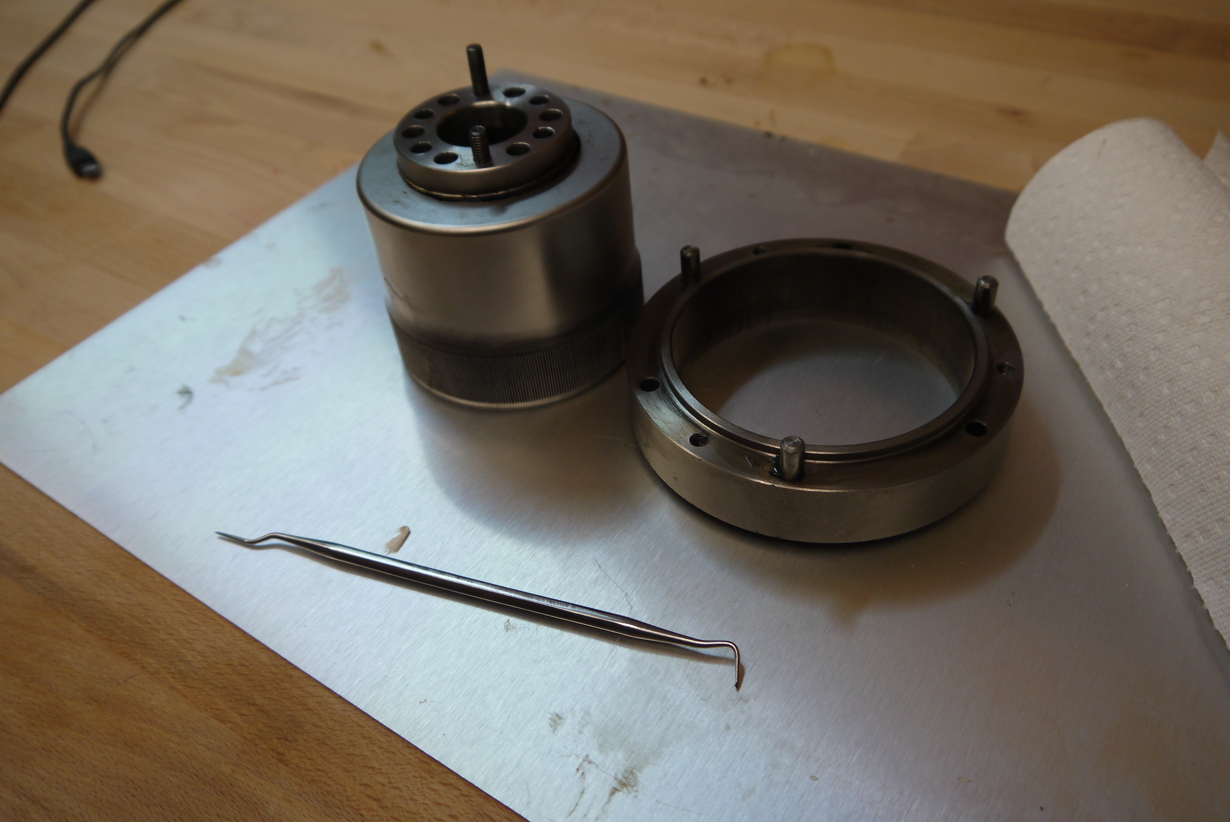
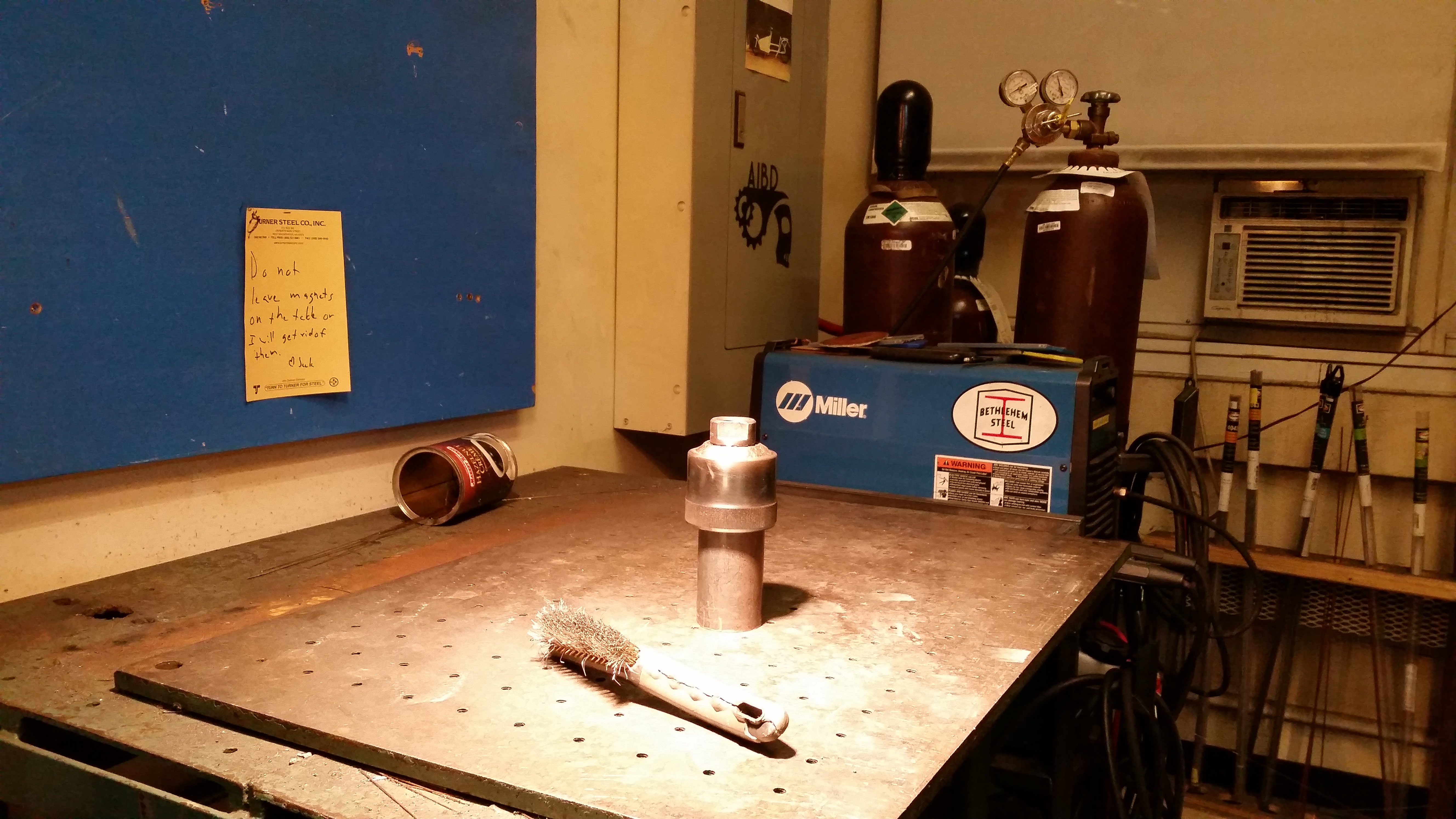
  Here's the removed
motor for theta-0. There was a lot of wiggling
as it is upside down, and inside the robot
cavity.
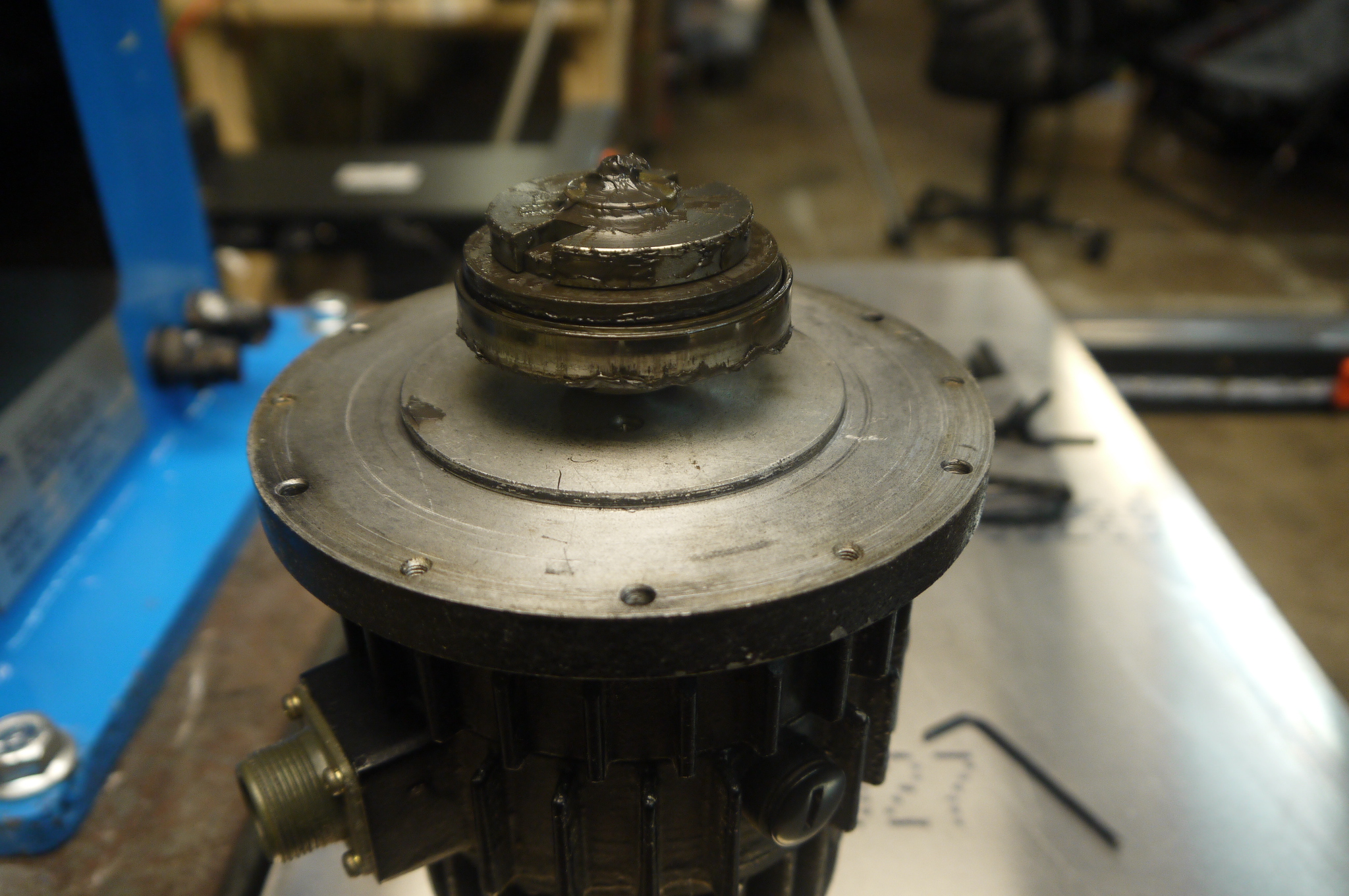
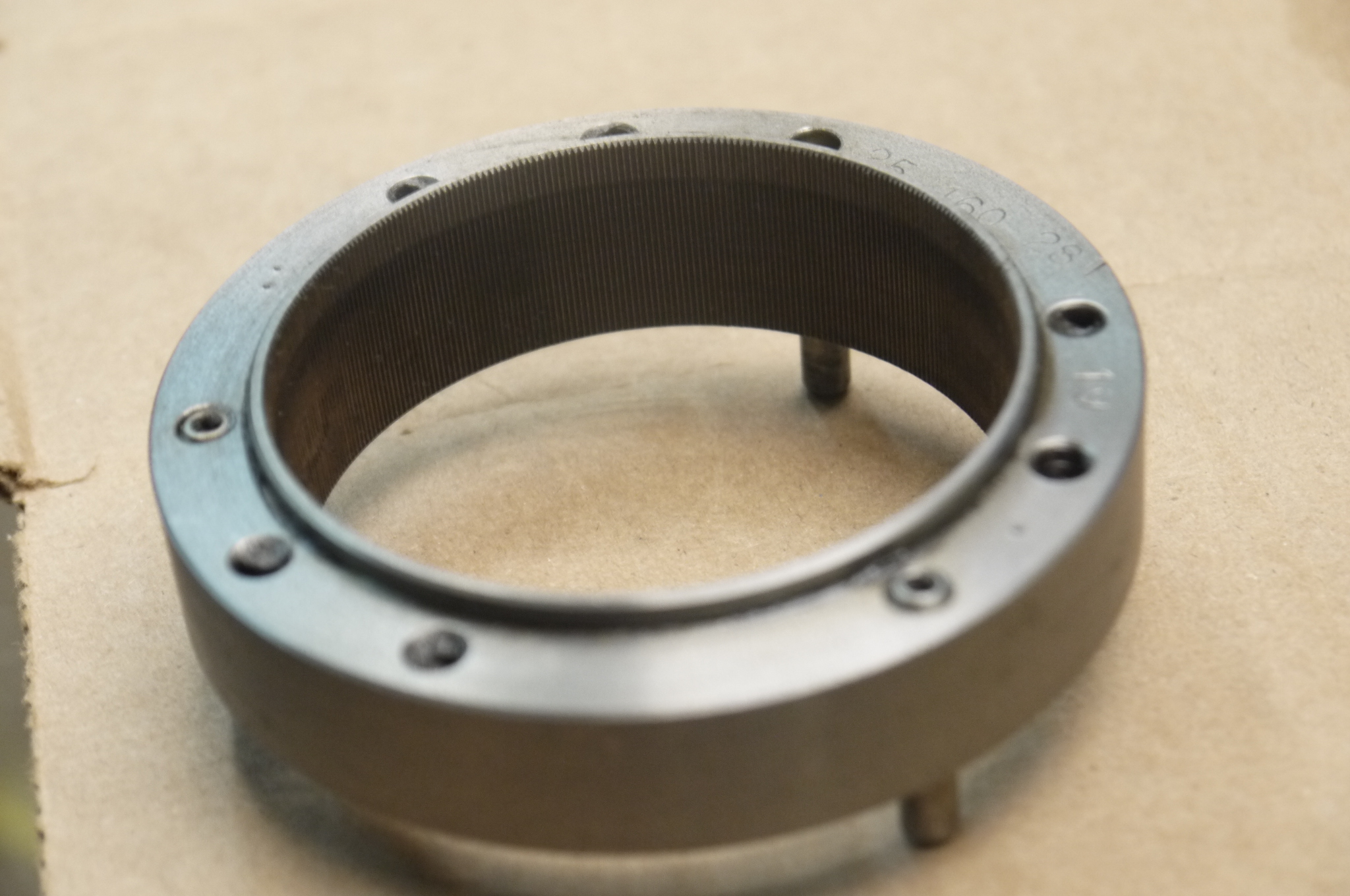
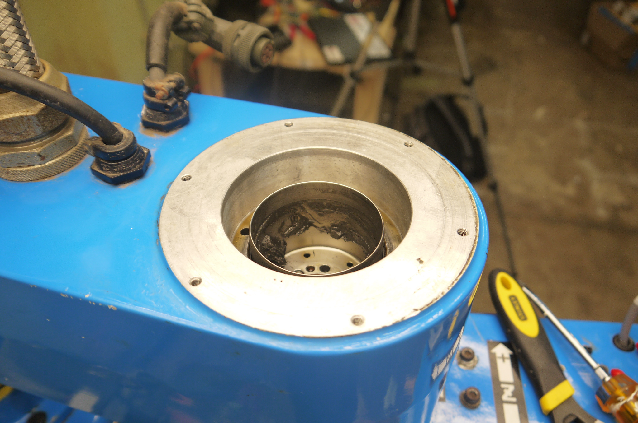
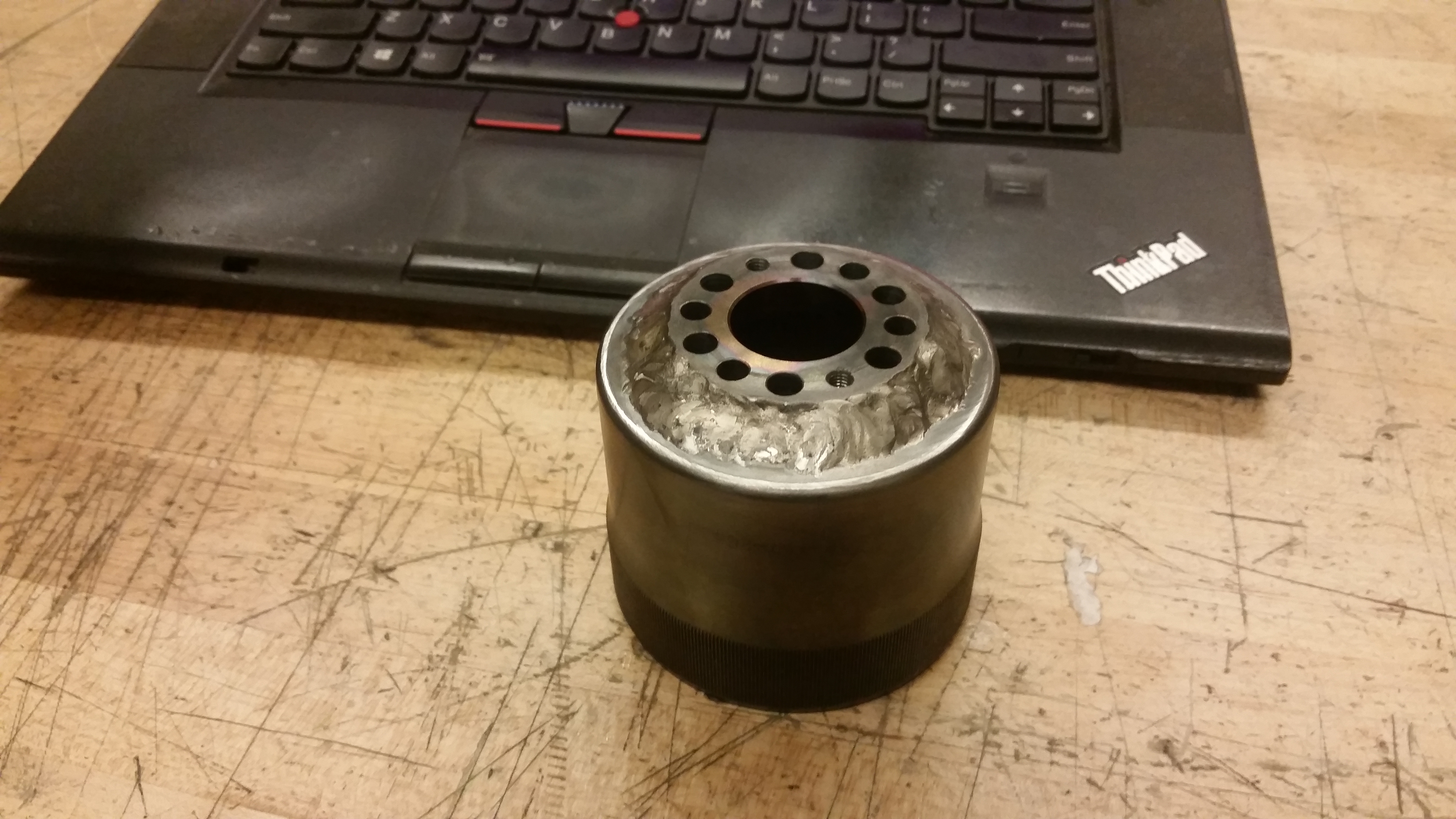
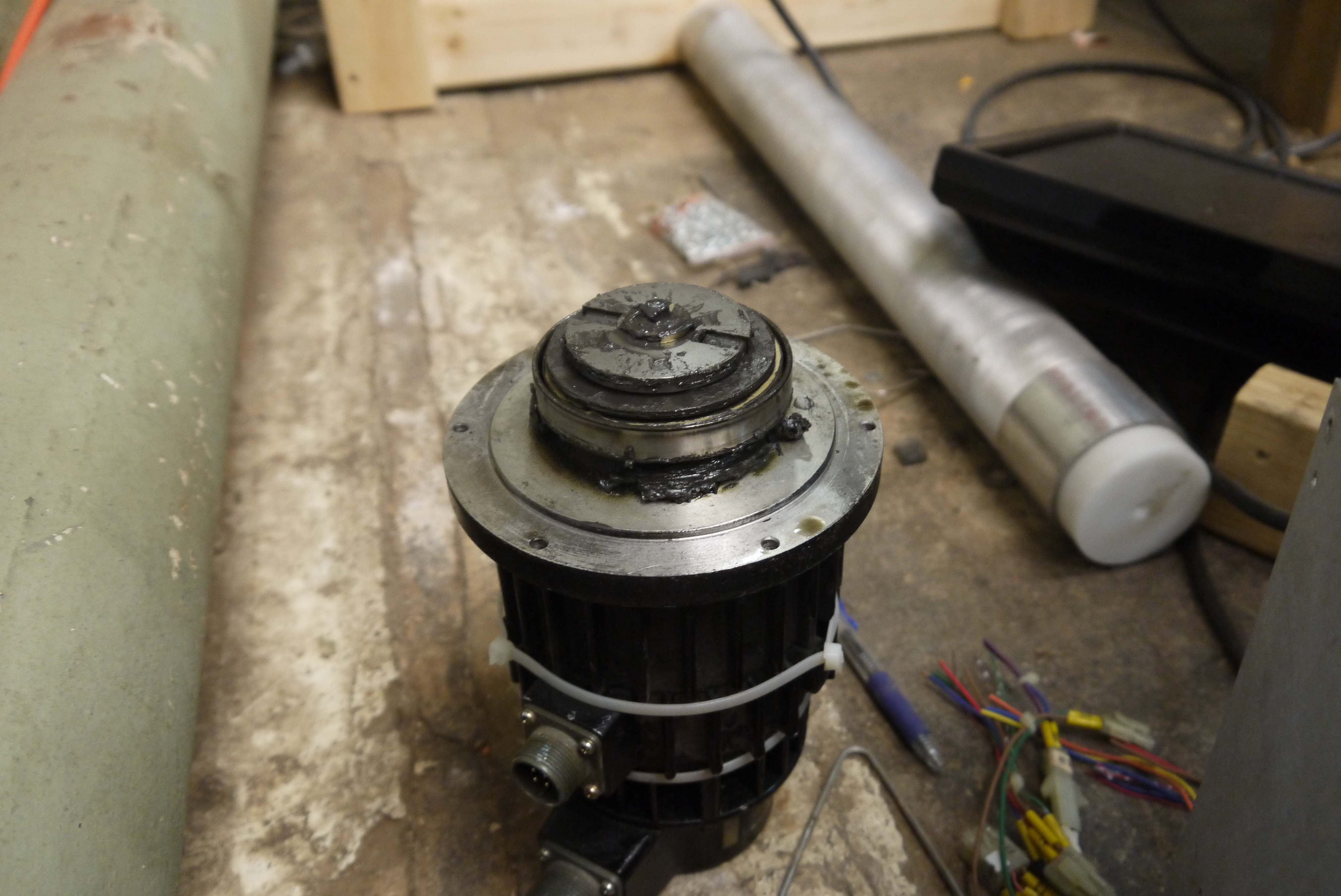  A
first look at the greasy sad gearbox. This was
kinda unexpected. The
flexible spline coupling sheared right at the
interface between the
mate to the robot and the flexible bit. I was
honestly more afraid that
all the teeth sheared off, given the noise it
was making.
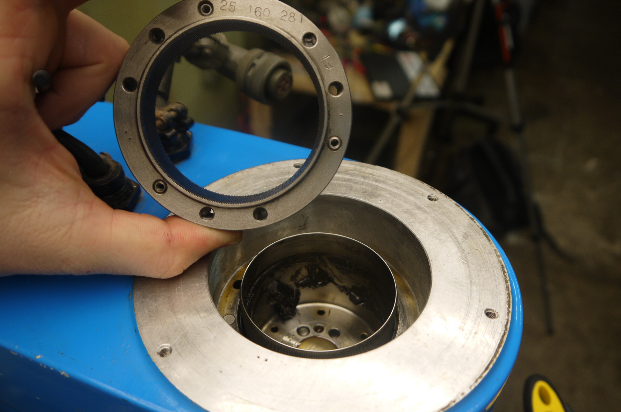
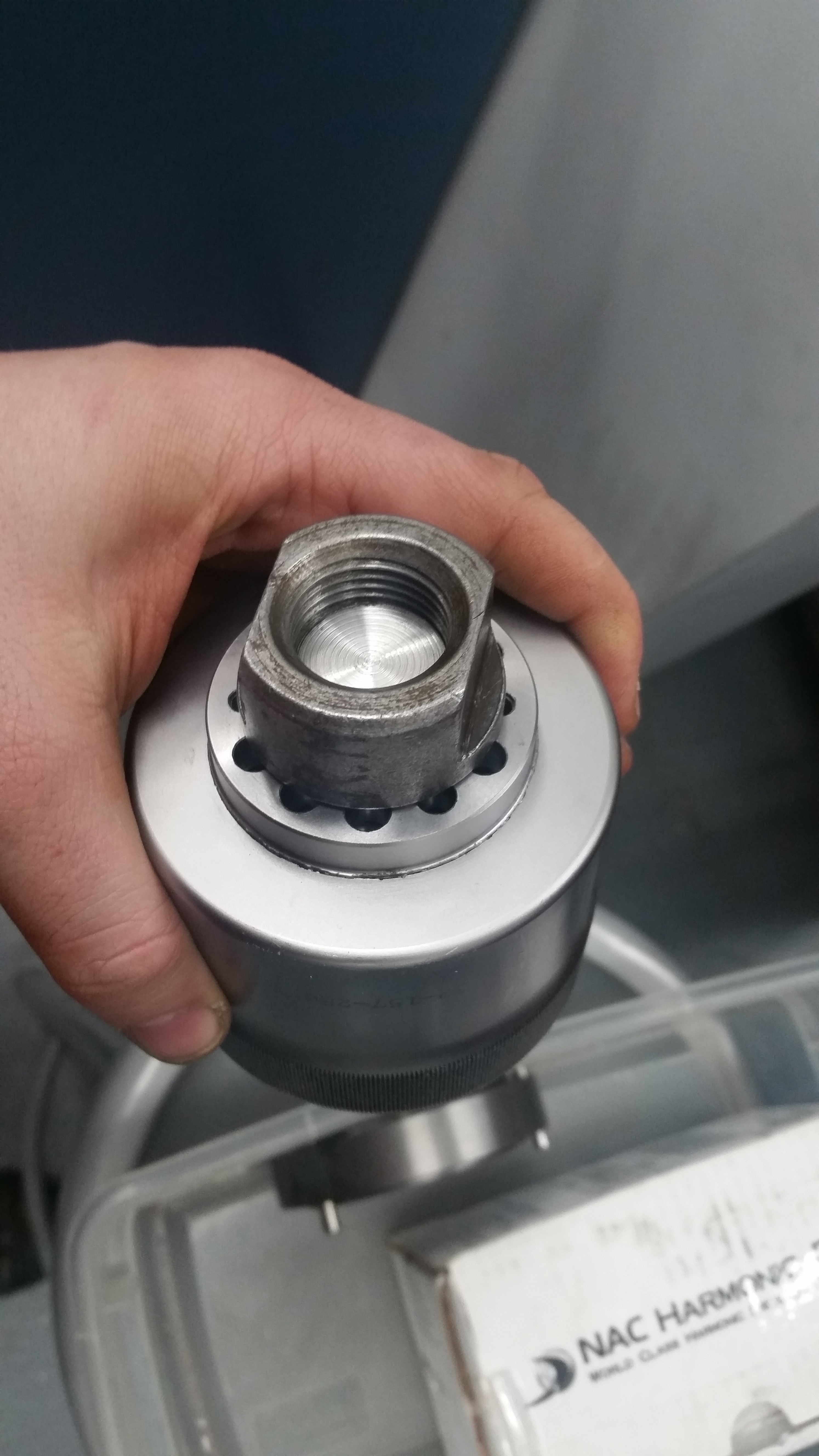
Next up: what material is this? Some digging online indicated that the flexible splines generally are a magnetic-stainless steel (400 series). MMM, its weld-able.... 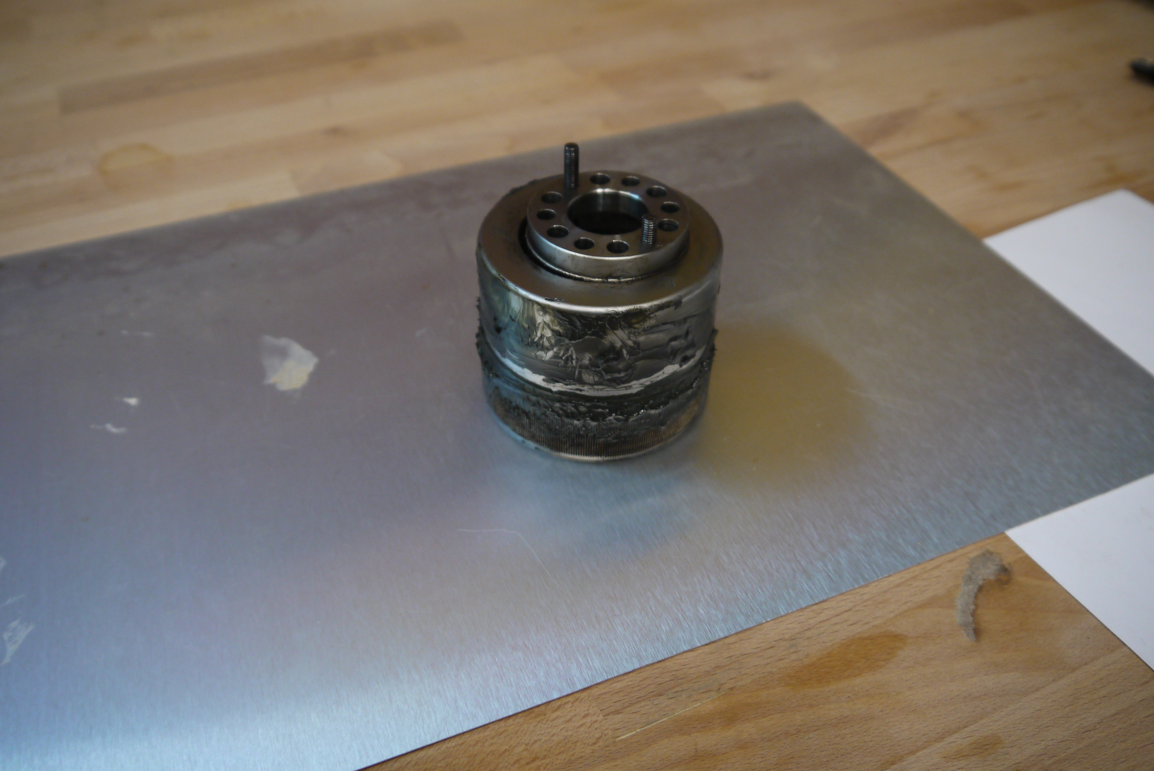 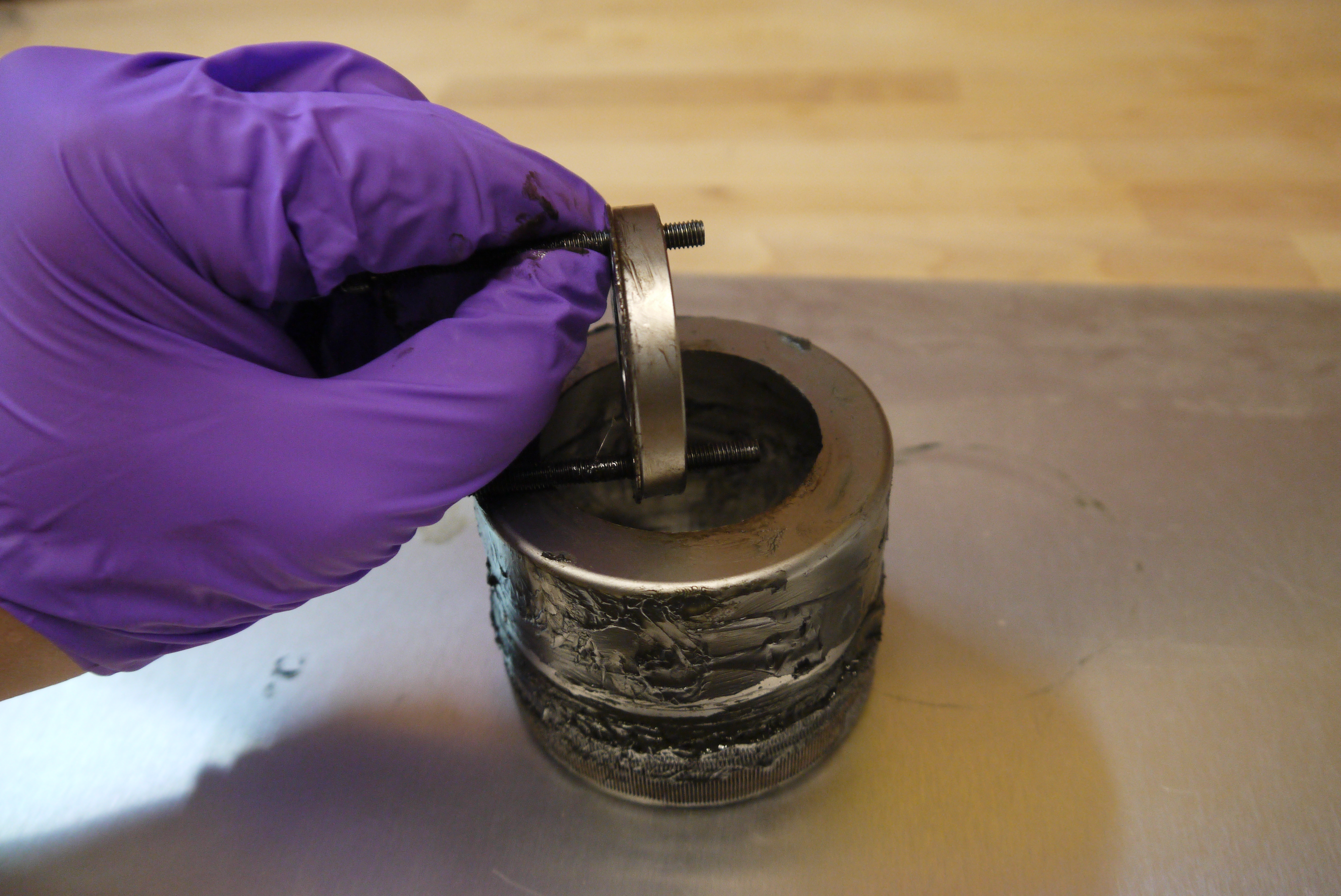 How are the
teeth holding up? To check the status of the
teeth, I wiped down all the gooey old grease
and cleaned each tooth with a.... Dental
pick. Surprisingly, they were indeed all in
tact. The failure could have been fatigue
driven and at some point the repetitive
stress probably tore/sheared off the thin
walled part. Here's where it gets
interesting.
  So,
given that there did not appear to be any real
interference between
the outside of the flexible harmonic, there didn't
really stand a reason
to indicate that it wouldn't suffer too much from a
weldment. My only
hold-up was that this is a flexure. Flexures are
delicate and changing the material properties could
end
poorly.
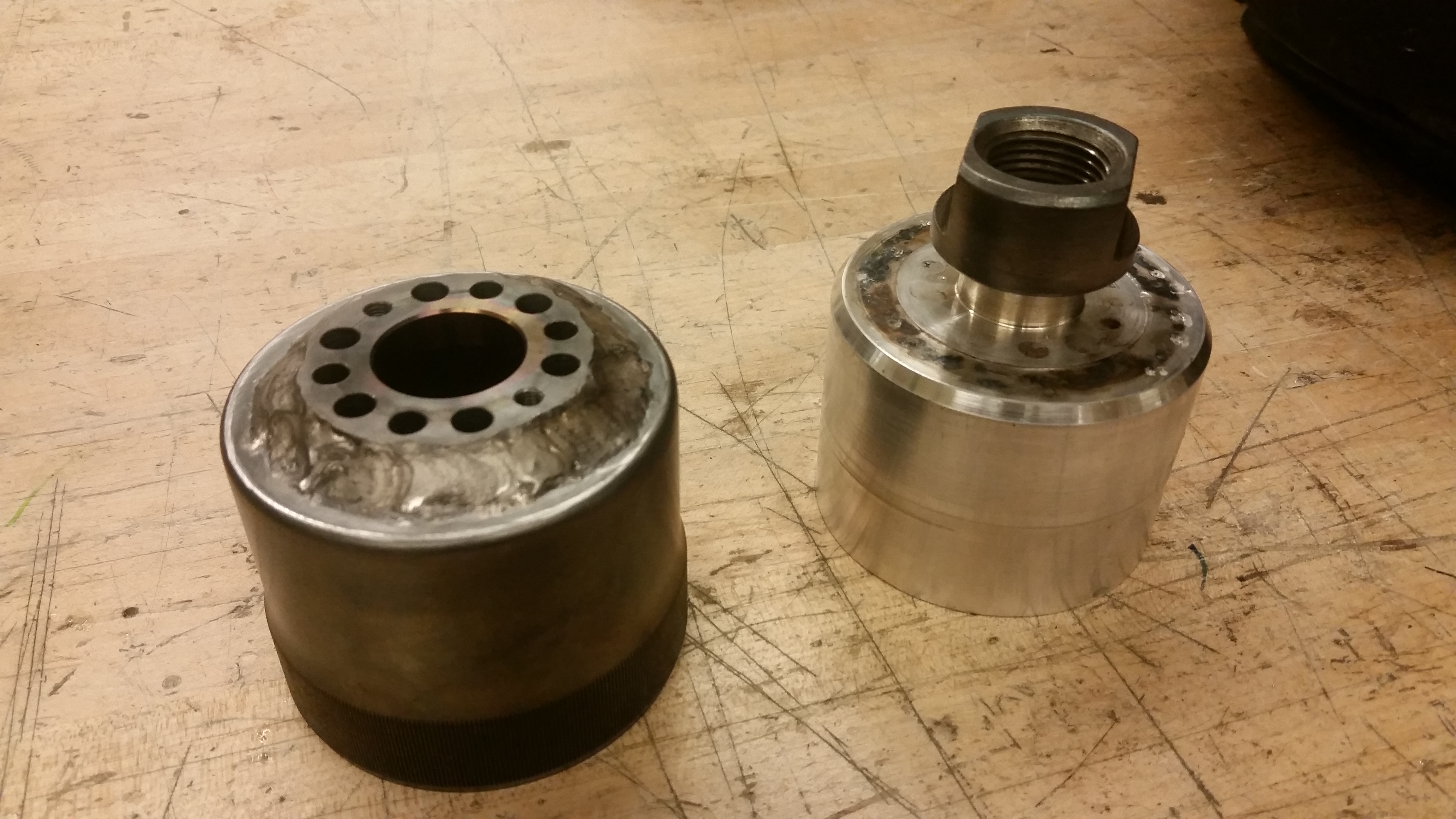
Now to figure out how to hold everything concentric to attempt a weldment. If i wanted this to work again I would need to make sure it was nearly perfectly concentric, and the jig to hold it like that would need to be made out of something that could survive the welding process without sticking to it, so no plastics / 3d printed parts. 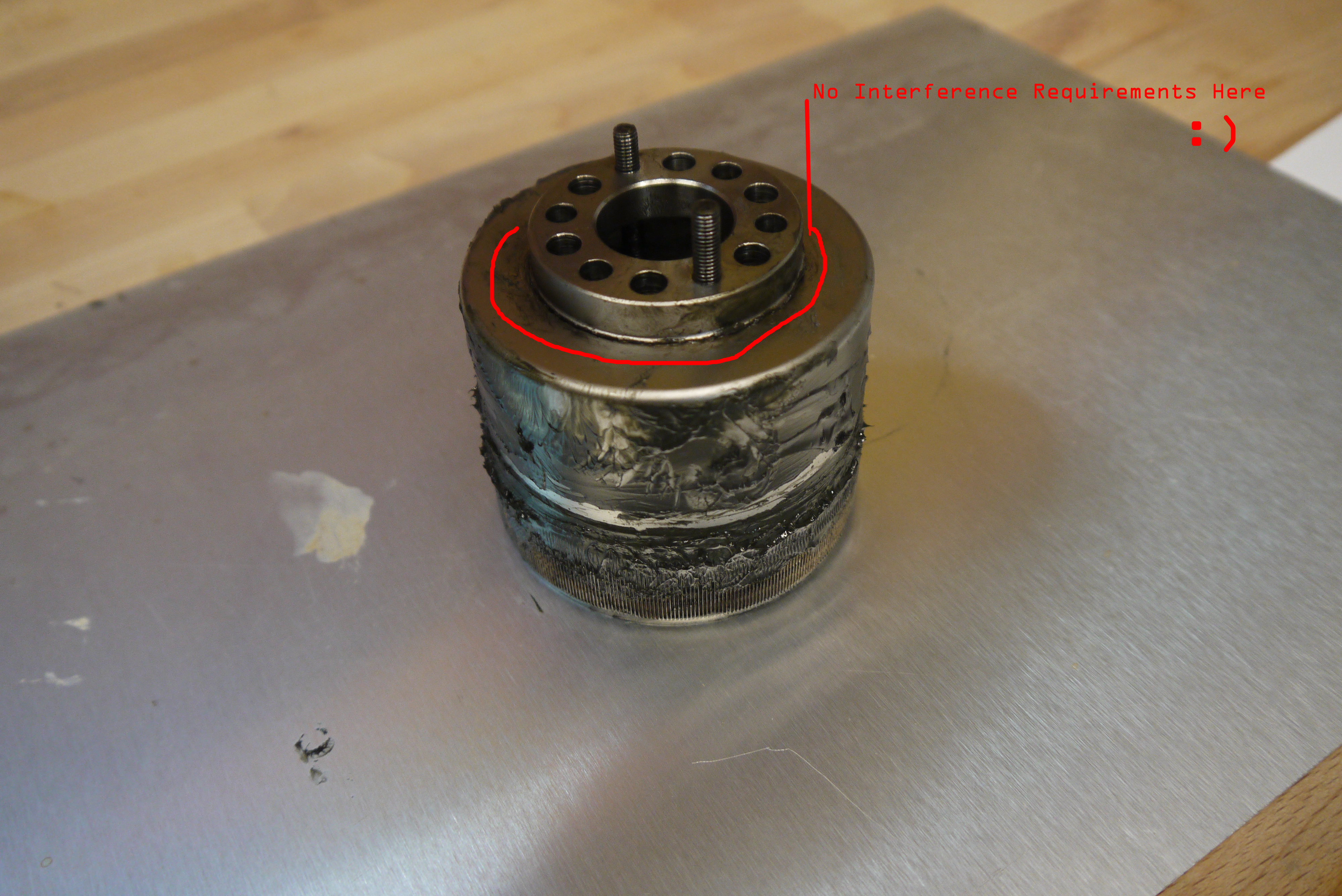 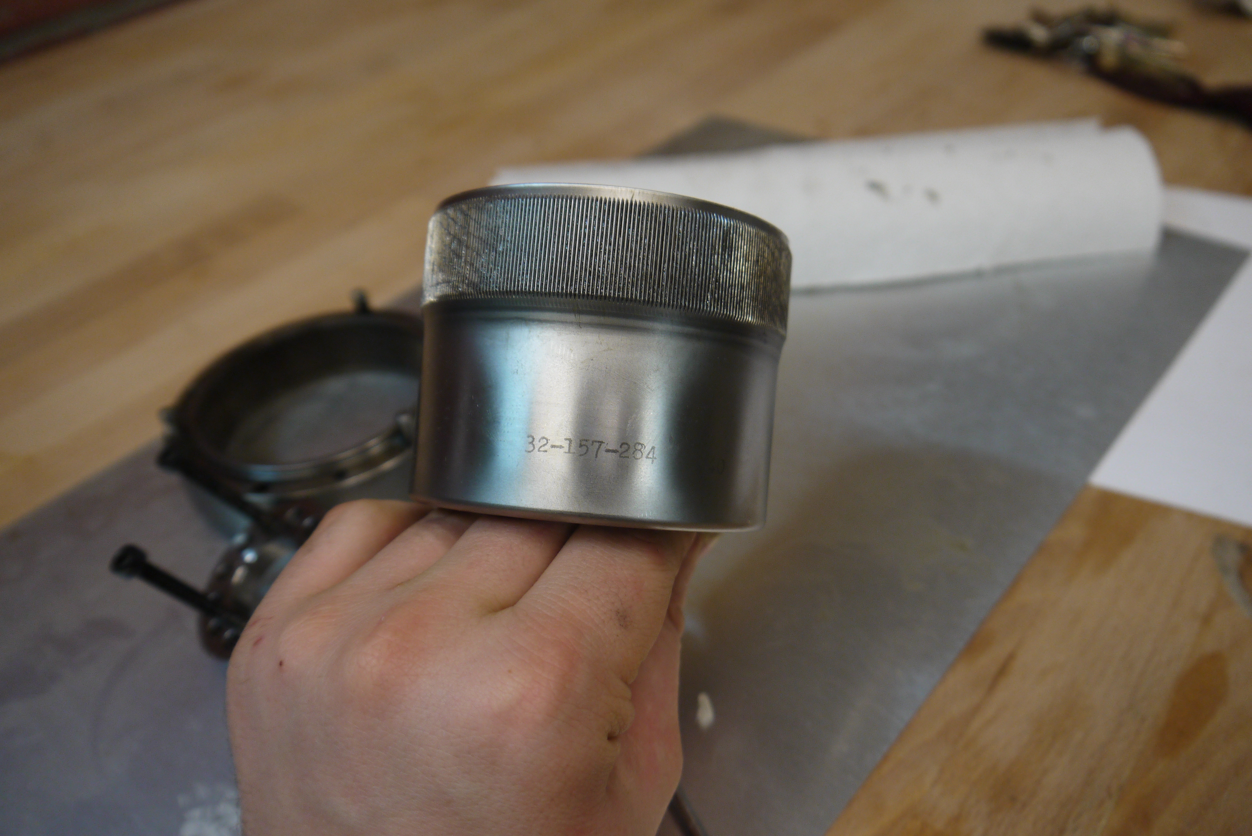 I
was conveniently bringing some waterjet parts
towards WPI one weekend and
was fortunate to have an insert turned to hold
both parts concentric.
The insert started as a 4" 6061 aluminum round.
A large draw-bar nut was
used to keep the part under compression.
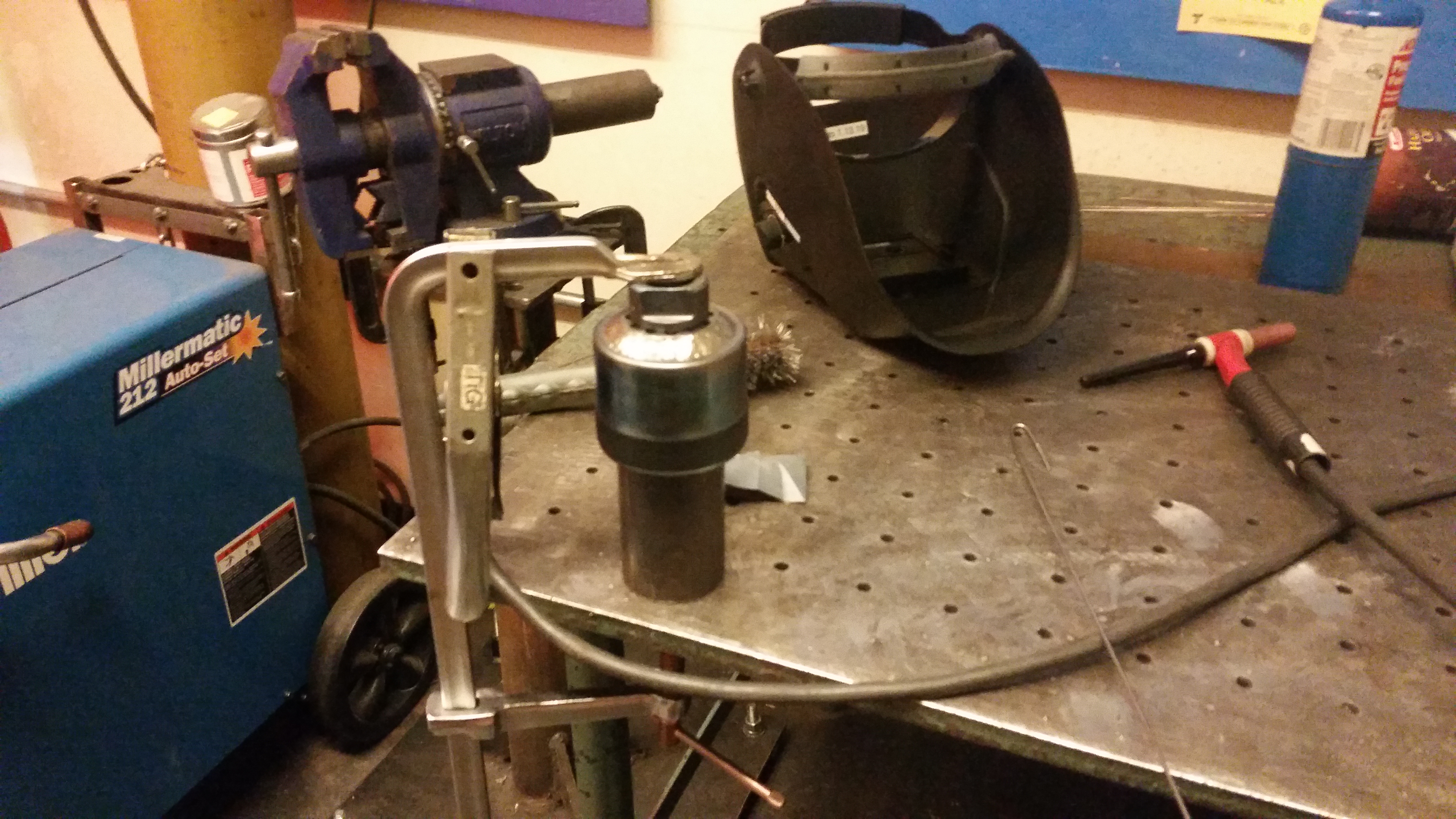
The thread for the nut was single-point tapped by Thomas Kouttron [link]. 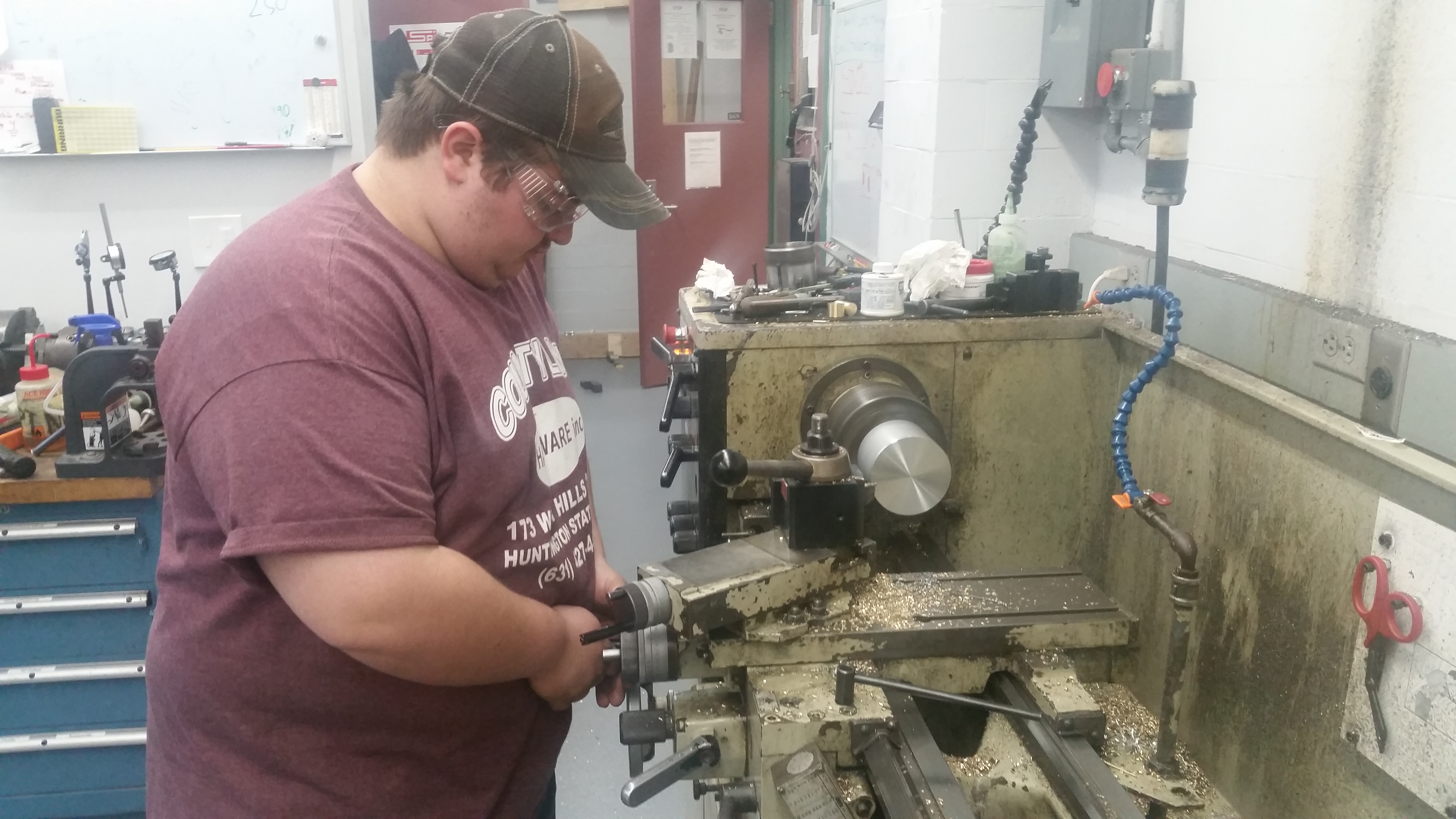 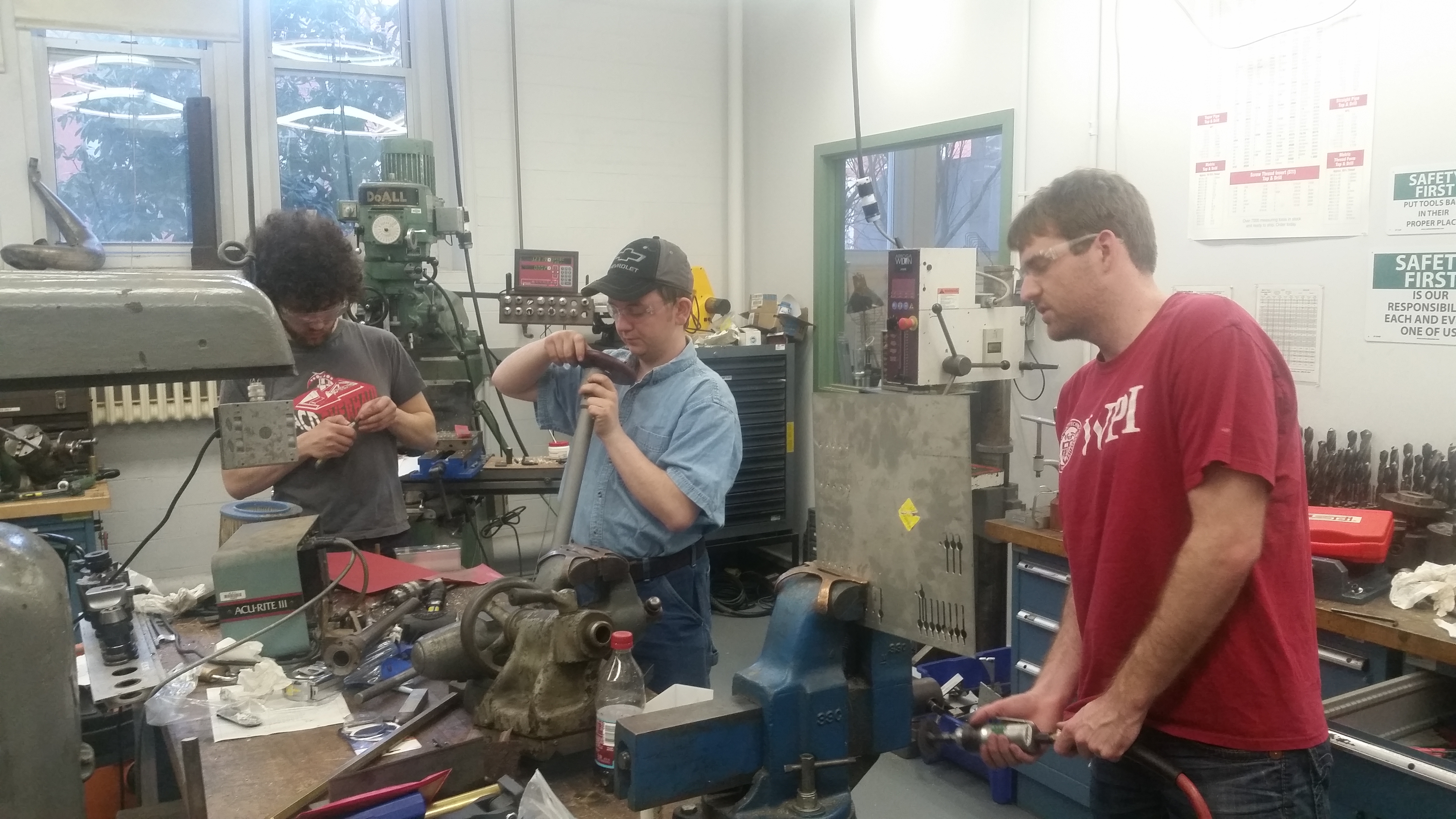 Here's the new mandrel that's going to be my welding jig. Having the sheared parts on hand allowed for a fairly snug fit. After the photo (below) was taken, threads were added for ~1/2-13 so a capturing nut could squeeze and hold the whole thing together. 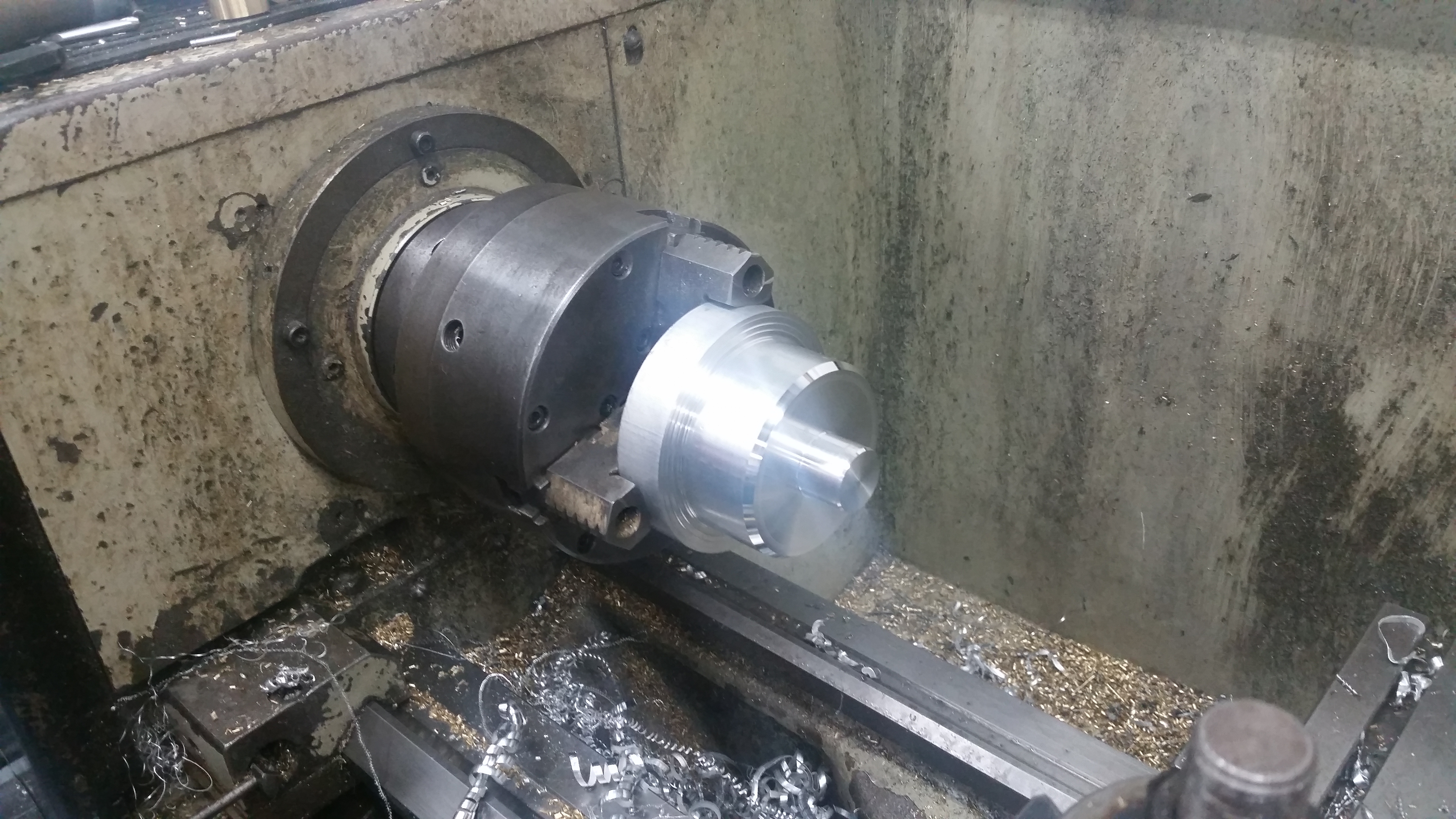 The broken harmonic drive with and without the mandrel: 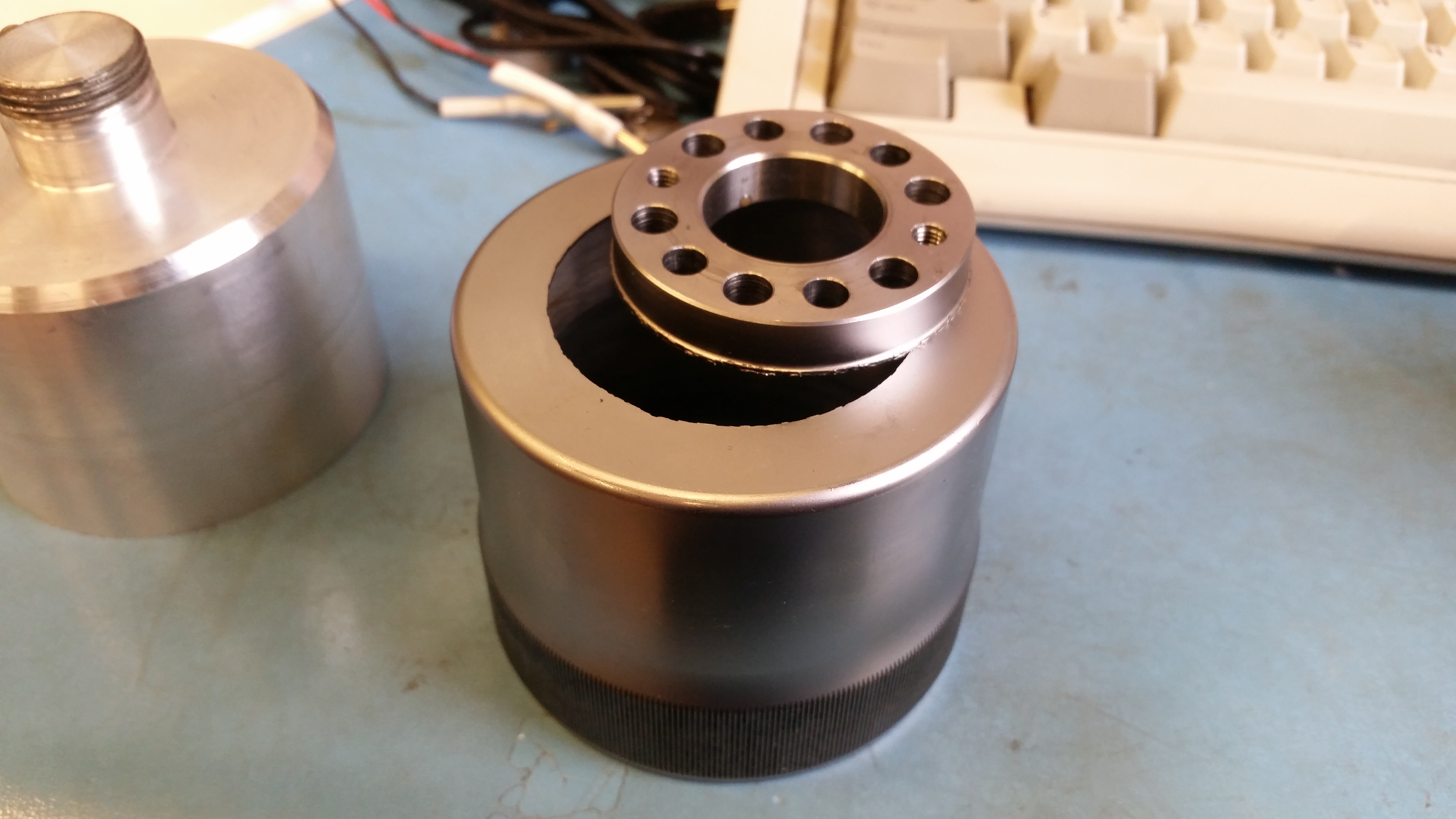 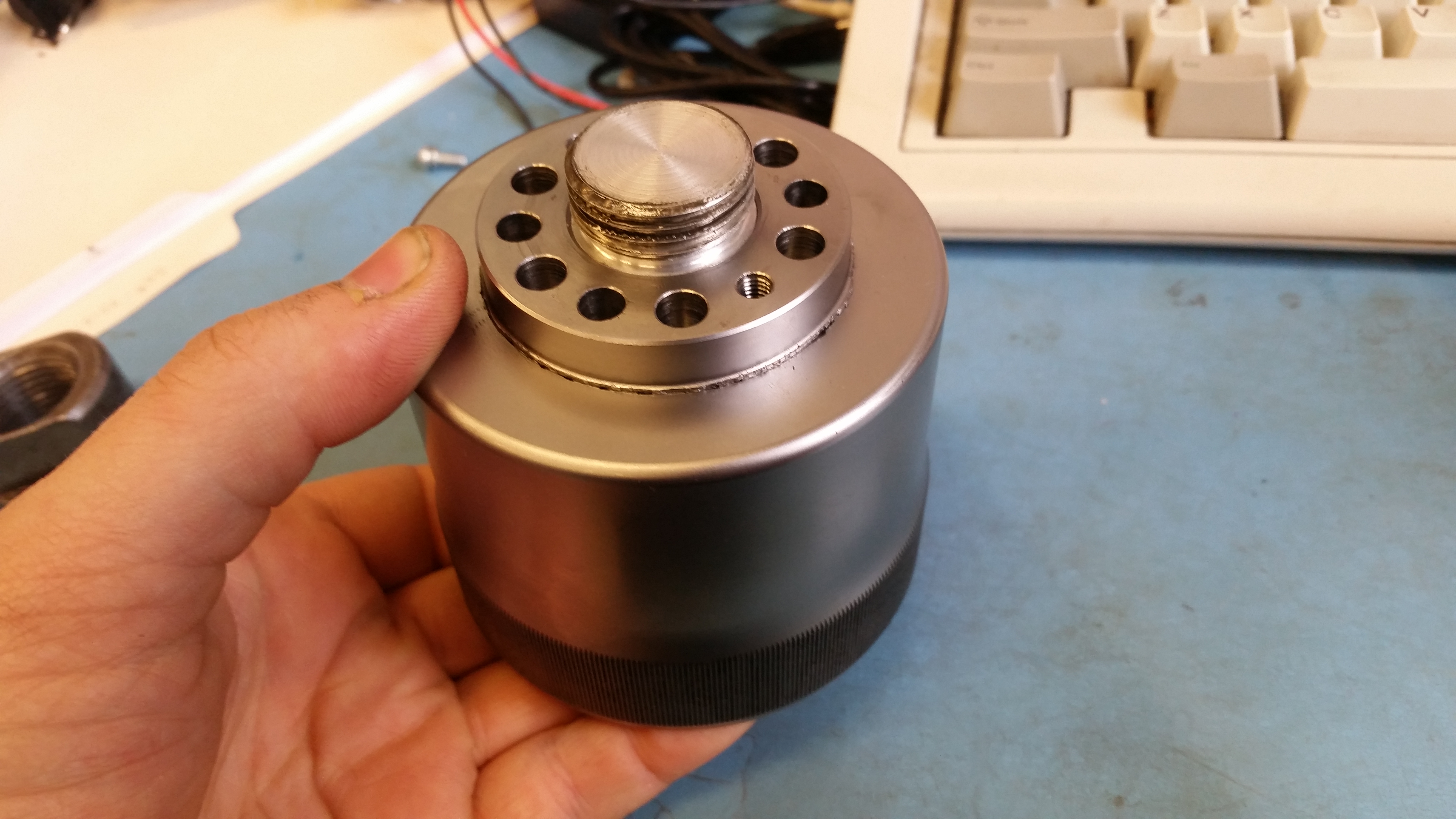 So here's
the jig holding everything in place
ready for welding. I was somewhat
concerned that the tig welding would be
really difficult as the aluminum mandrel
is a comically large heatsink, but the
small relief angle was enough of an air
gap that things were not too bad.
  As
it turned out the insert was a bit short so
a steel round was used to
prop the teeth up off the table. If the
flexure was sitting on the
table, weld current would flow through and
nominally cause pitting. I
scoured the mating surface with a flexible
sandpaper block and
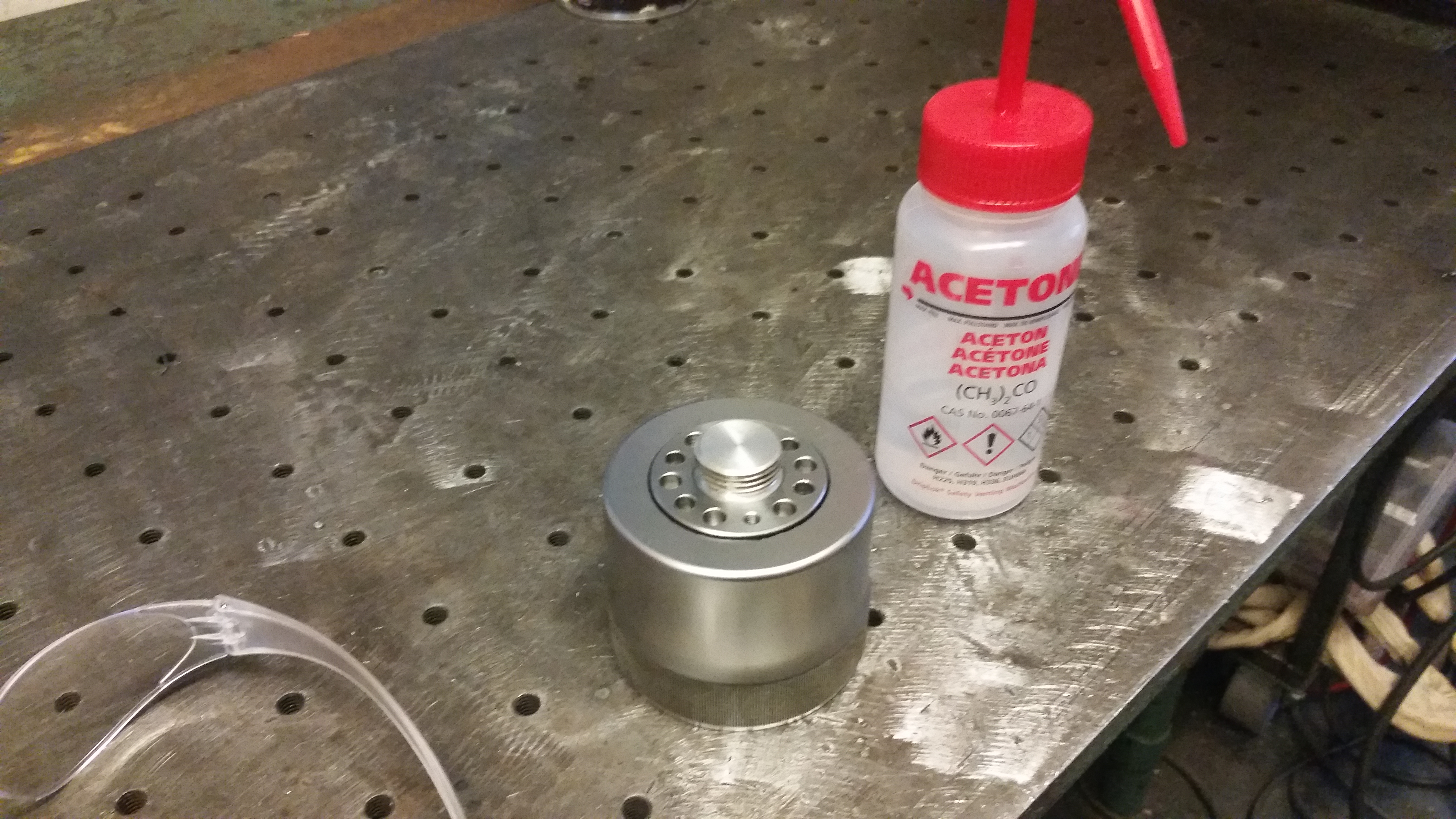
then proceeded to Acetone-wash the surfaces
before welding.
  I
was super anxious about welding this part as there
was little room for
error (a stray arc on the teeth would be really hard
to correct). The
welding actually was quite quick. I used a stainless
filler rod and
cranked up the cover gas flow. Ok i went a little
overboard with filler
rod. The big issue was the incredible thickness
difference between the
top and flexure. I started at the thick mount
surface and made my way
down in small bursts to the thin walled flexure,
trying not to chew it
up.
 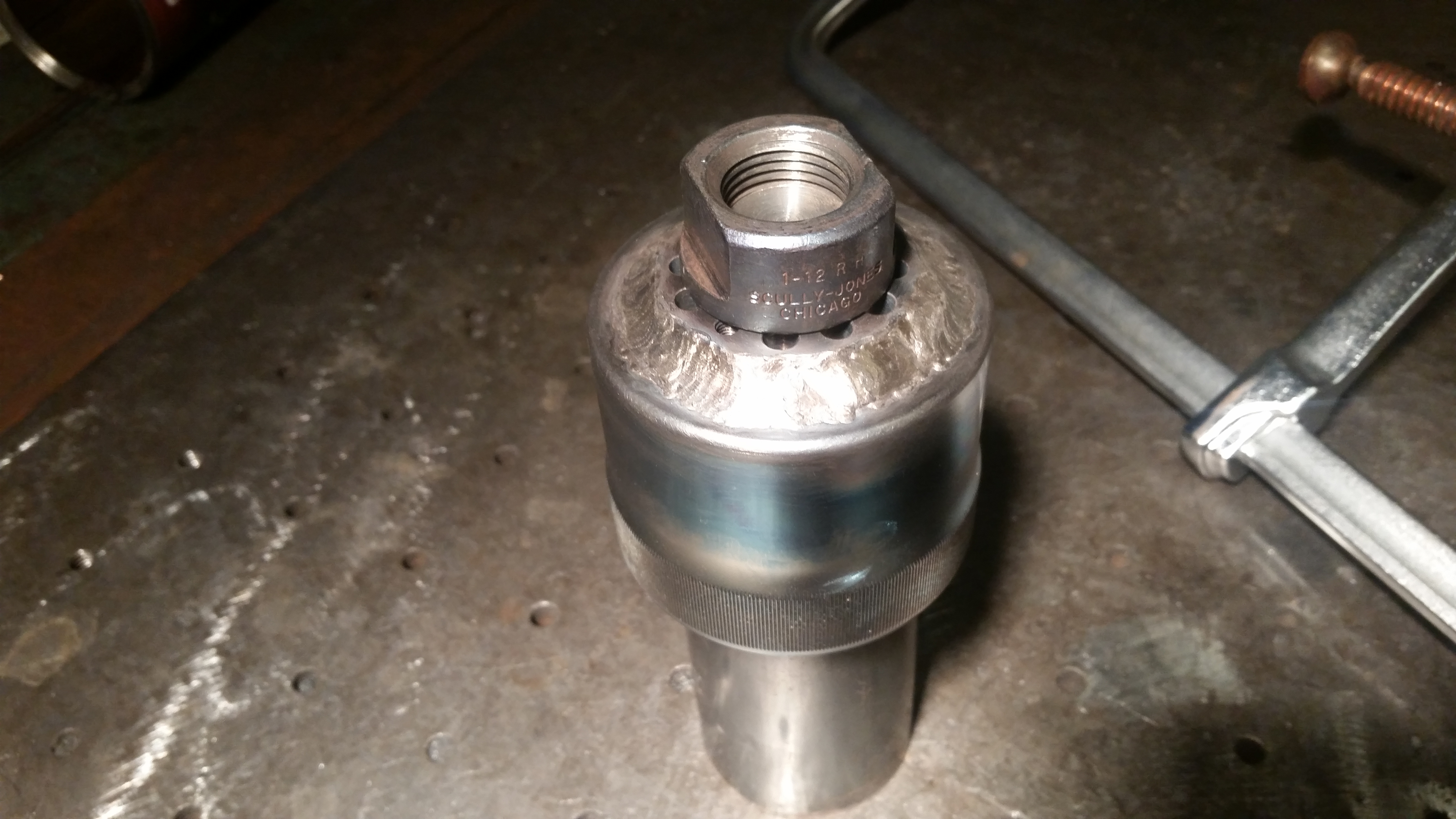 Here
it is, pre-cleanup. I was fairly careful about
thermal buildup, but in
the welding environment it was difficult to see any
discoloration. this
fixture also did not have a channel for a back
cover-gas. Stainless generally needs a cover-gas for
both sides for it to remain stainless,
if I were to do this again, I'd try and boring out a
path for rear
cover gas. Otherwise it came off the jig without too
much struggle. Its
'quite structural' Given that this was
initially (probably)
hardened, i used a file to check if it still was, on
a face right above
the gear teeth. The file didn't catch in, so that's
a good sign!
  |
(There's other
photos in the photo gallery)
Concluding Remarks:- Give
If you have questions or comments, ask below or send over an email.
| Comments: |
|
HTML Comment Box
is loading comments...
|
Dane.Kouttron
Rensselaer Polytechnic
Institute
Electrical & Electrical
Power
631.978.1650