Dane.Kouttron
[11.10.21] Auto Darkening filter for DSLR Camera [Quick Project]
 Have you tried
filming your welding with a normal DSLR? Does it
look terrible? Have you tried
filming your welding with a normal DSLR? Does it
look terrible?Is there a quick way to record video without damaging your camera or getting washed out by the small sun inches from your thinly gloved fingertips? Come on down and hit print! |
| What? |
Conclusion | Image Directory |
Measurements and CAD |
|
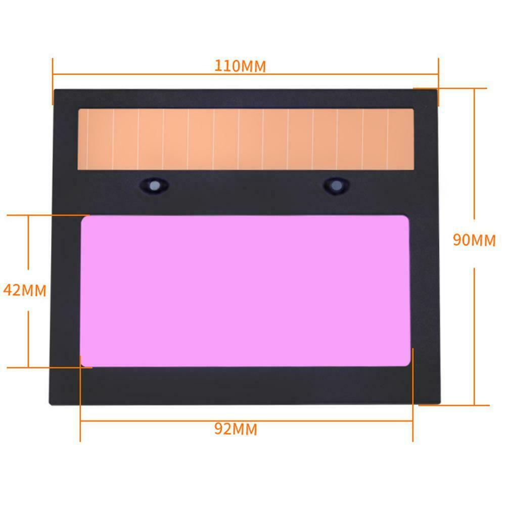 One of the important
bits here is the actual viewing area. If you have a
giant full frame camera, you're mildly stuck as the
viewing area of this particular insert is smaller than
a full frame sensor, or at least likely smaller than
your camera lens. The viewing area is 42 x 92mm, so
your view may be slightly cropped. One of the important
bits here is the actual viewing area. If you have a
giant full frame camera, you're mildly stuck as the
viewing area of this particular insert is smaller than
a full frame sensor, or at least likely smaller than
your camera lens. The viewing area is 42 x 92mm, so
your view may be slightly cropped. This is the target facing view of the auto darkening filter. The top contains a small mono-crystaline solar panel, which, based on settings on the user-facing side fires a comparator and applies a driving potential across the auto darkening filter. 'But wait what about the turn-on delay, will UV hit my camera before it triggers?' likely not, as the Borosilicate glass used on the front part of the LCD has poor transparency for uv light. You are literally looking thru an LCD, when the filter is 'on' the LCD is 'on' and blocking the light path. The amount blocked is proportional to the drive current used to feed the LCD. |
|
Print Print Print
|
|
Thermal inserts
This is always my favorite part, thermal inserts! This design just uses two screws for tensioning the lens attachment ring to the print. Off-screen i threaded a 25mm screw into an M4 thermal insert and heated it with a hot air station. While its possible to use a specific soldering iron insert, it gets cumbersome to have a large assortment of inserts and specialized tools. Its also possible to heat up the inserts with a lighter or candle, but it does leave a carbon residue on the insert. Hot air works surprisingly well and the fully threaded screw helps prevent melted plastic from getting in the threads. |
|
Fit checking and attaching the lens ring
The two M4 screws are threaded in, through the inserts. The ring itself has a small lip that helps with the screw grabbing and keeping the ring in place. The print bottom helps hold the base of the adapter ring, with the two screws applying pressure holding it in place. The attachment is fairly sturdy, you can tug at it without it budging. I was opting to use thumbscrews in the final version but they were somewhat a long lead-time item. |
|
Friction fit
With the lens ring attached the welding screen can be inserted. When I initially designed the cad for this adapter i debated having a latch or a long part to grip the top of the filter module, but it turned out a friction fit worked remarkably well. I think its important to note that I'd likely only be using this in fixed setups on a tripod, not moving around or upside-down. Part of this is defined by the tolerance of the printer, its also possible to add a flexure to the design that gets shifted when the welding filter is installed. |
|
Lining up the ring to the lens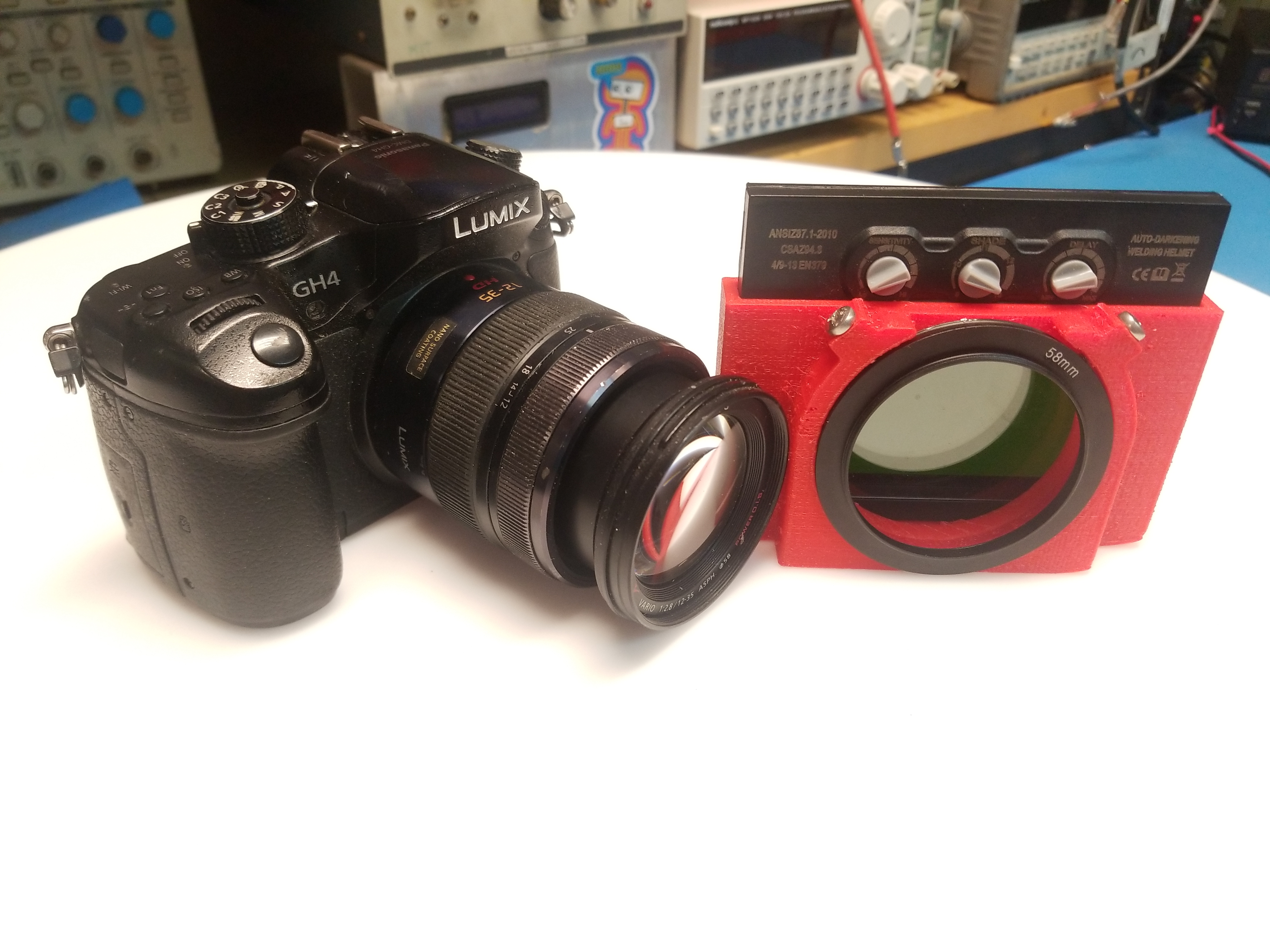 So you're about to thread on the 3d printed gadget with the captured ring adapter to your lens and you find out, its not quite level!? Fortunately you can loosen the two screws, rotate the assembly until its matching the alignment of the lens and you're good to go! Everything fits, but is still easily remove-able with either threads or screws. I need to find small, tall thumbscrews that don't obscure the small adjustment knobs, so a tool is not required to adjust the lens mount position. |
|
Everything
fitting together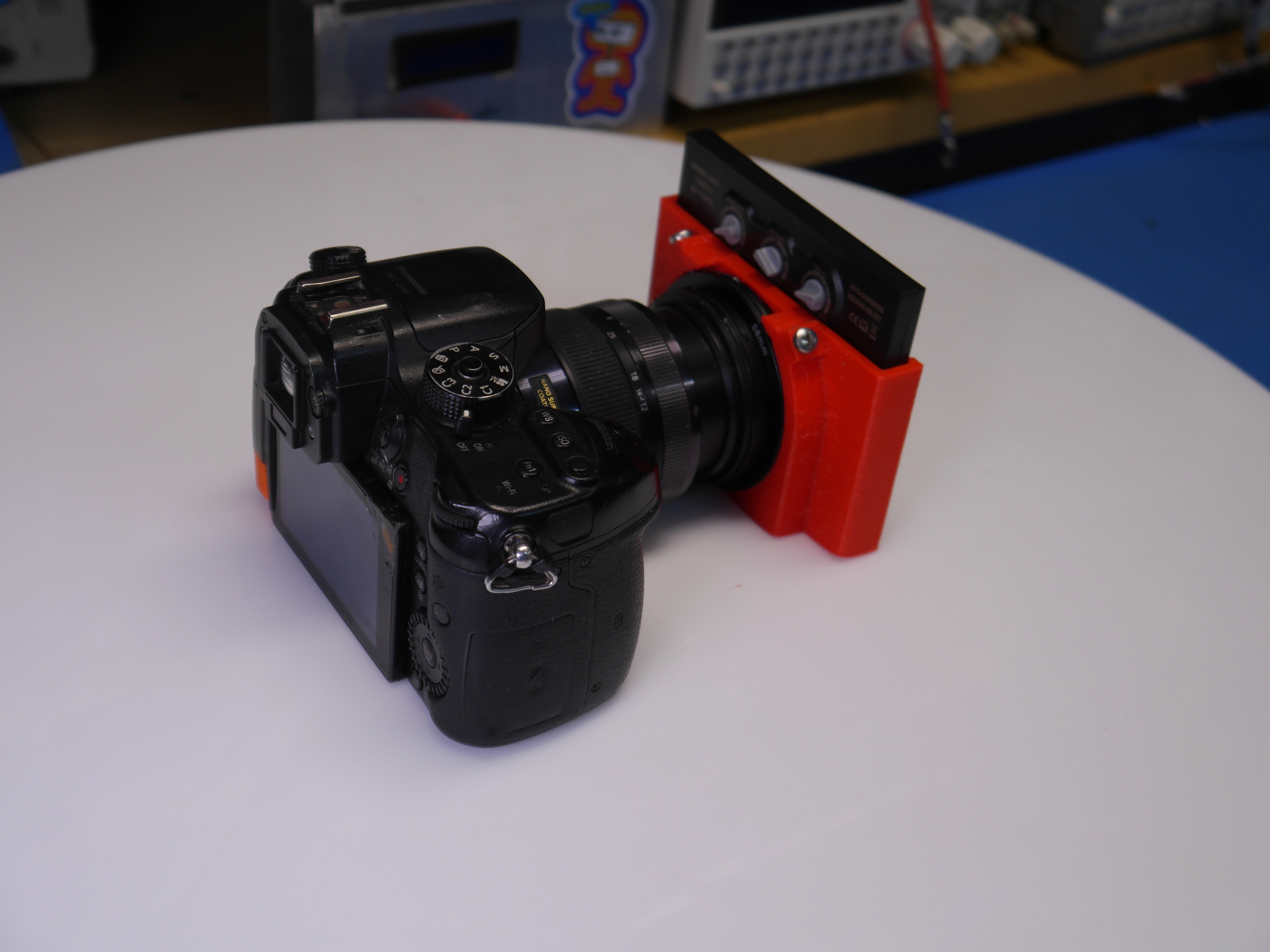 The adjustment knobs for the welding filter are accessible, but not so much if you have ginormous hands. Its always possible to slide out the adapter if the knobs are just too recessed. I found that realistically there wasn't too much need for twiddling, as getting the camera settings right is already miserable for welding. Generally if you're working alone you're not welding and also camera fiddling. To try out settings I ended up pointing the camera at a high power incandescent light bulb. My goal was 'simulate a lot of light and a hot thing without having to also be welding at the same time'. Ideally, you should be able to see the incandescent bulb coil heating up, and be able to see the coil under all the extra light. Some shots below show how different settings effect how this is visible. |
|
<I'm trying a new format with more animated video clips, bare with me I'm sorting out what works well>
(There's other
photos in the photo gallery)
Concluding Remarks:If you have questions or comments, ask below or send over an email.
| Comments: |
|
HTML Comment Box
is loading comments...
|
Pack your homemade drone batteries safely, less they become inadvertent lithium hand-warmers.
Dane.Kouttron
Rensselaer Polytechnic
Institute
Electrical & Electrical
Power
631.978.1650