Dane.Kouttron
[09.02.22] Video Call / Cyclotron Beam Sign
 Share a building with
some noisy folk? Want to let them know you're on a Zoom
call / have a charged particle beam running? Share a building with
some noisy folk? Want to let them know you're on a Zoom
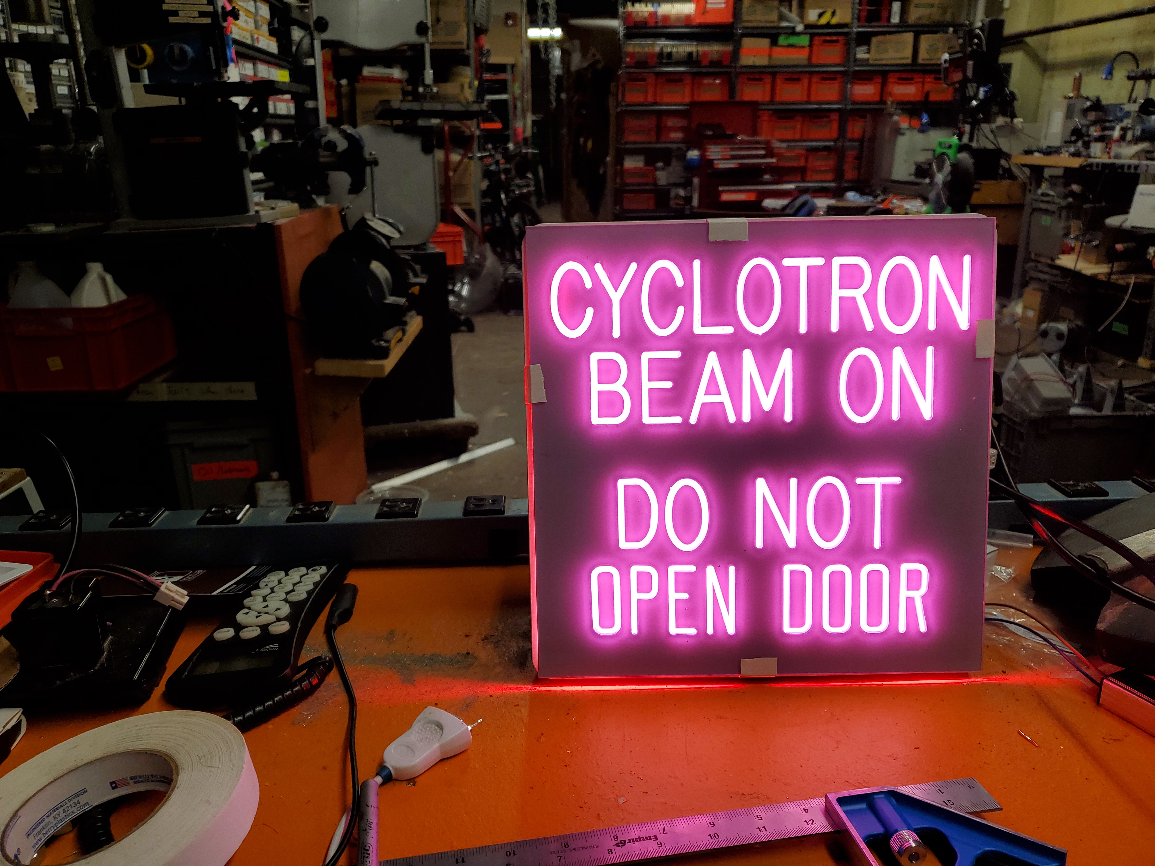
call / have a charged particle beam running? I have the solution for you. The goal started with retrofitting a historical sign with an LED back-light and then morphed into polling the zoom video meeting service for meetings and actuating the sign automatically. Stay tuned below for some contraptions. |
| Background
& Some Hardware The cyclotron building was one of those WW2 'beater' buildings with a buildup of machinist detritus and 'old science' leftovers. Huge steel tables, musty old filing cabinets and leftovers from international space station projects. A big boat-anchor of an electromagnet sits at its heart and large shielding walls protect the surrounding classrooms / offices. In late 2021 MIT demolished the cyclotron building to build a separate college to commemorate... <checks notes> a corporate landlord. MIT formerly did not have internal 'colleges' but now they do [link], its really bizarre. My best guess is that it will operate like the Sloan school of management, where its part of MIT but its also its own entity with its own rules. 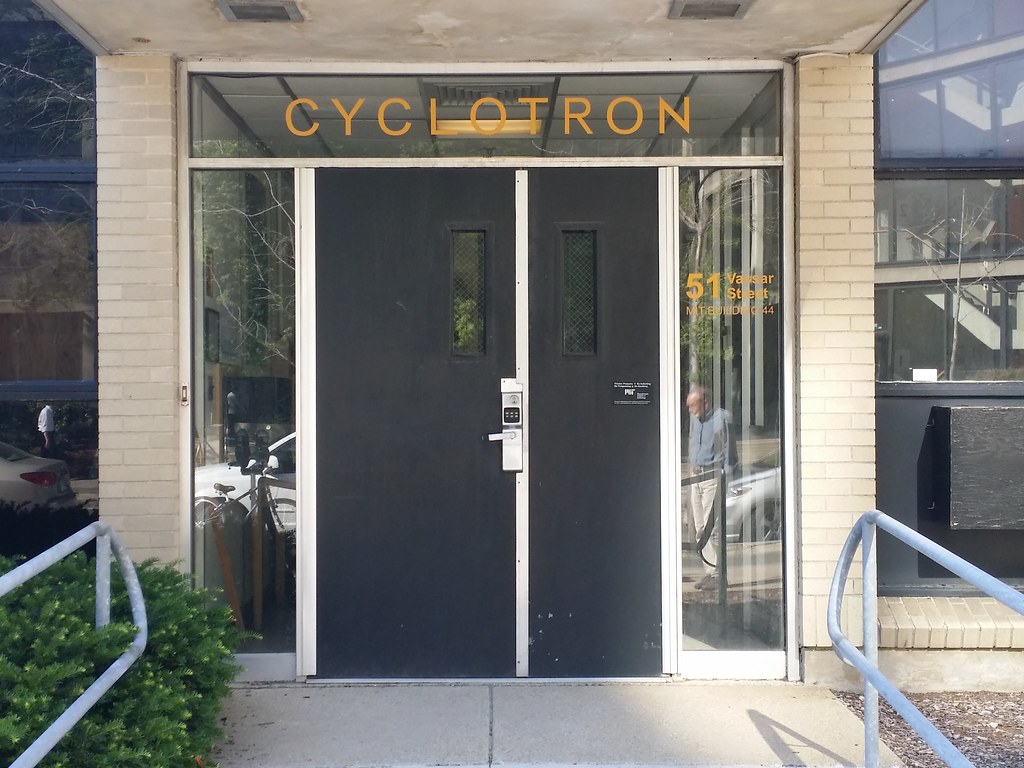 Inside the former cyclotron building was a support-machine shop for the physics department. It was crowded with old lathes, drill presses and mills. A huge roll-up shielding door sat in between the machine shop and the cyclotron room and an adorable sign on the wall probably indicated when the beam was on. This was pre-laser cutter so this was engraved with a 90 degree engraving bit. I saved the plastic insert part of the sign from destruction along with some other hardware.Thanks to the MIT property office being surprisingly expedient for deactivating MIT property. It's in the process of being restored, instead of being industrial construction waste. Whats somewhat surprising, it wasn't clear *when* these stopped being used. The Hendey lathe itself had some fairly questionable motor drive belt, that resembled more of a barnacle than a v-belt. Its possible this machine shop stopped being used 5-10 years ago. A lot of the leftovers from that room were equally in a state of frozen time. 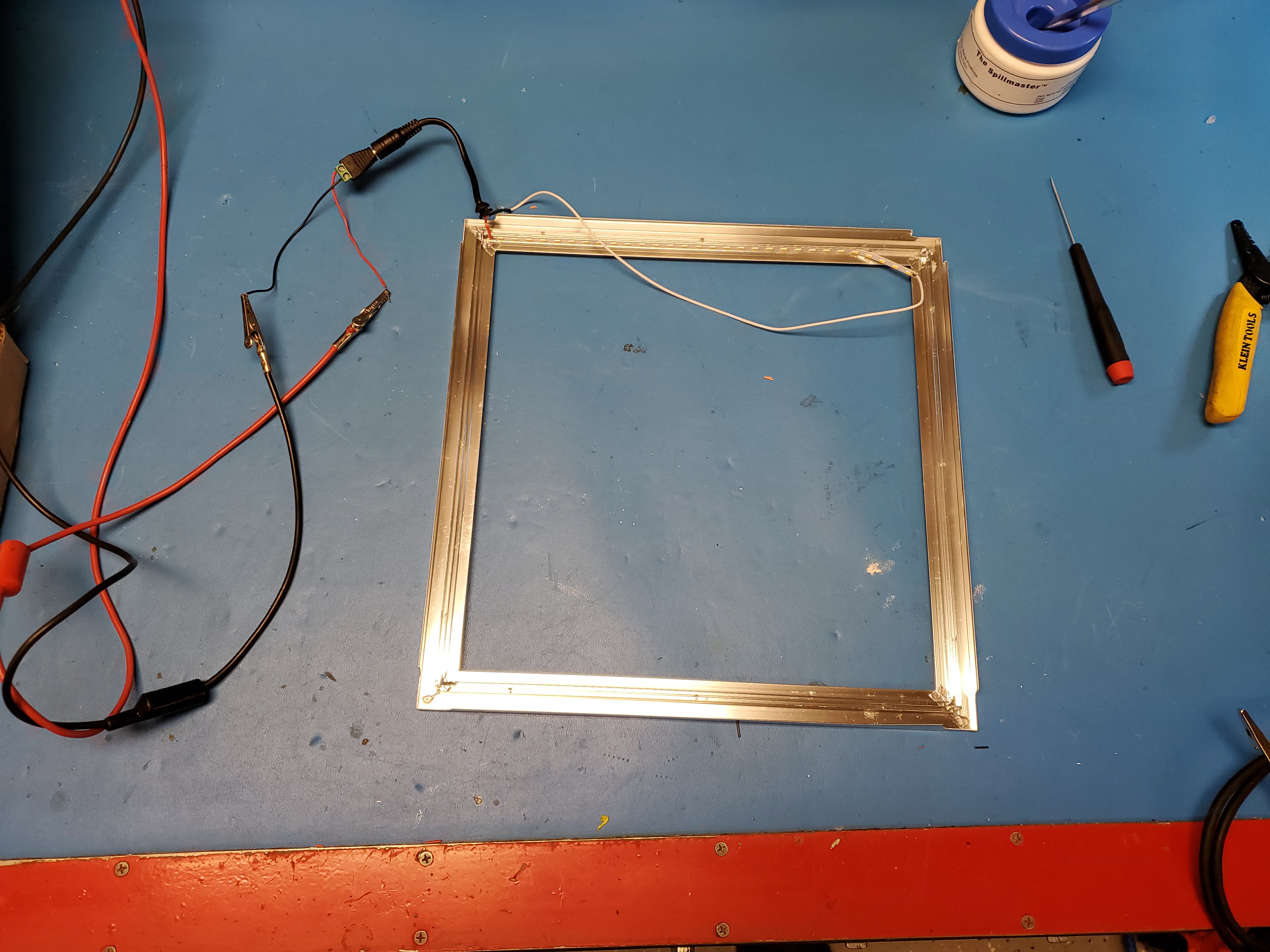 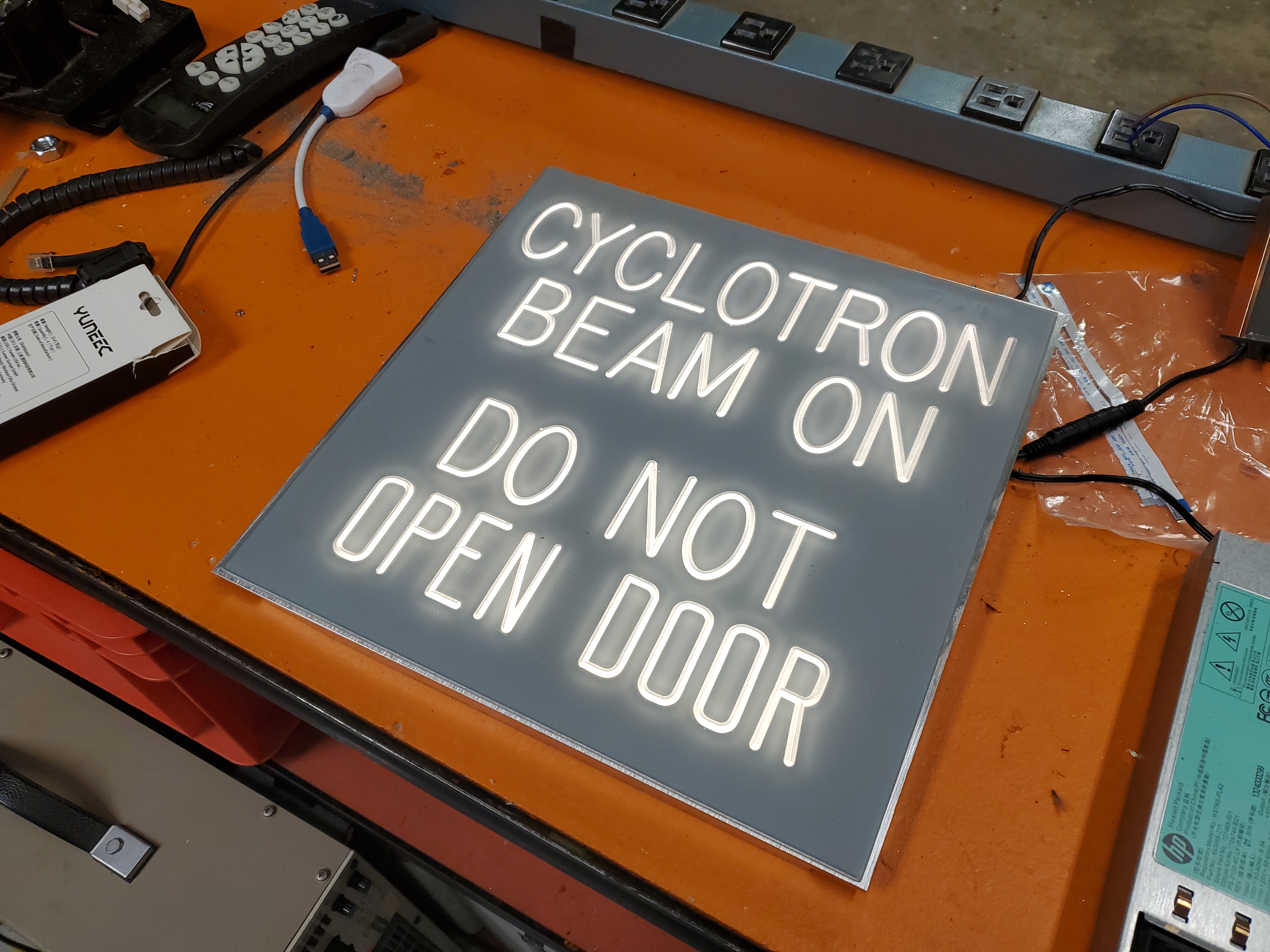 My first go at an LED back panel for this sign was this eBay sign. Admittedly it was incredibly cheap, but it was also incredibly mediocre. A single strip on one side of the square was the light source. Shown (right) is how bright the sign was at full power, somewhat not impressive. The sign then subsequently failed after a few minutes. Given its construction this was not surprising. Either way this was fed from an external driver that took mains and made ~26v. 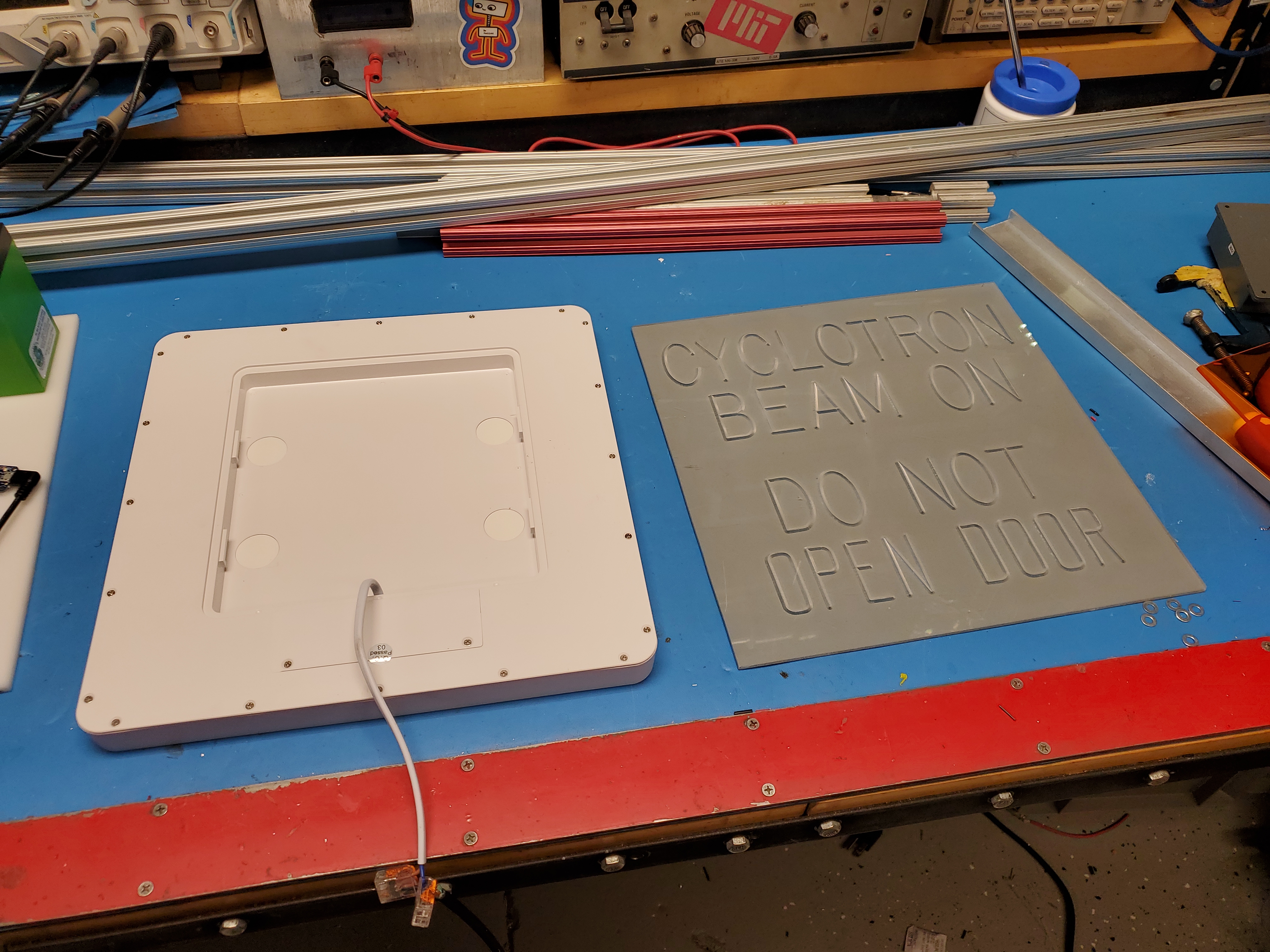 With the failure of the eBay special, I opted to grab something off of amazon. I picked up [link] which was 3X as expensive as the eBay module, and I assumed it would 'just work'. This was not the case. To be fair, when mains was applied it did power on. The internal power supply did run the light fixture and it was incredibly bright. It was the right size, mechanically. But way too bright. 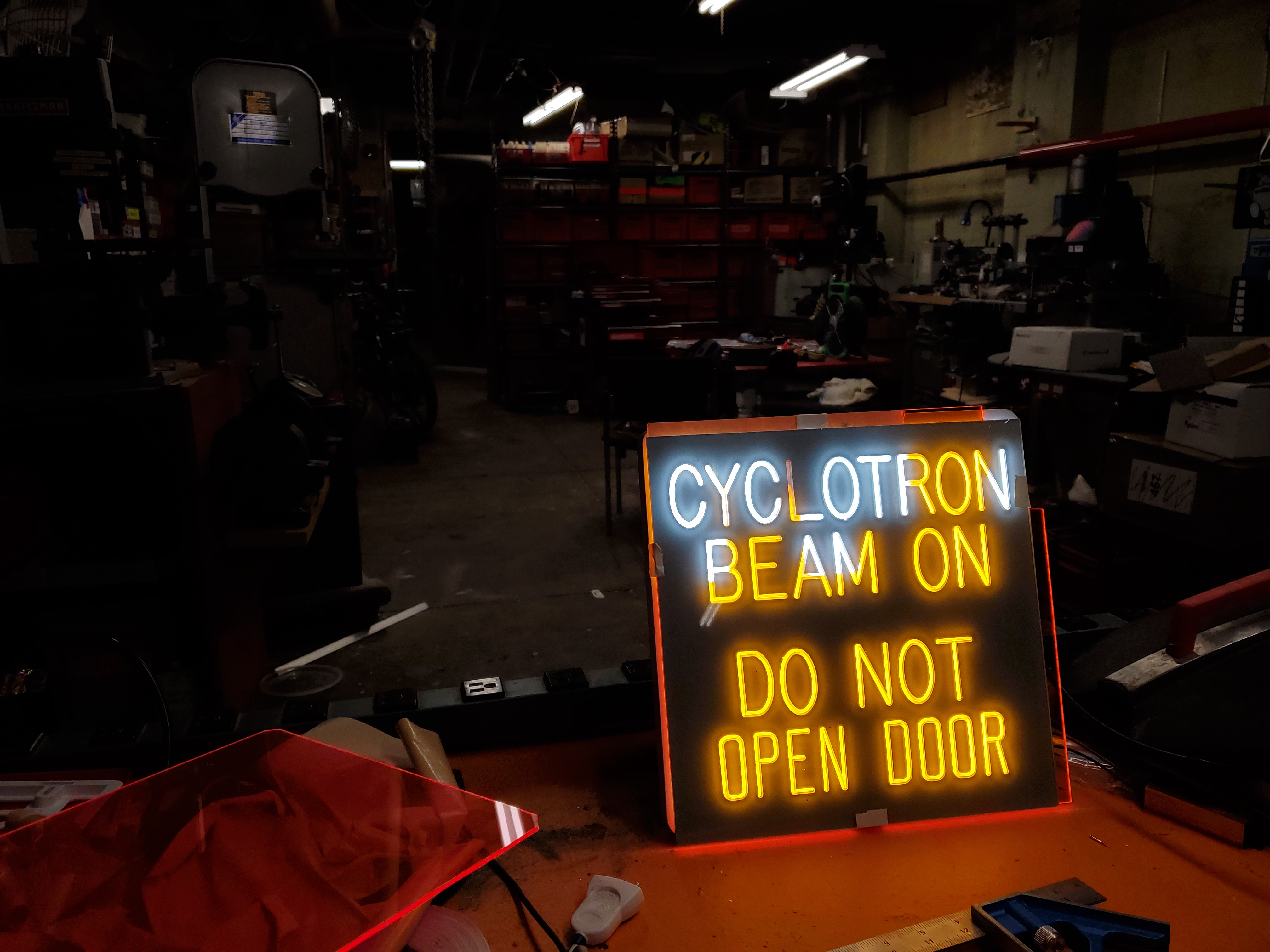 With some broken colored acrylic sheet sitting in between the sign and the light it was still *INCREDIBLY BRIGHT* like, the background of that room is normal lighting. I had to dial down the exposure just to get both visible in the same shot. I debated just going with it, but was probably a good idea to dial down the power if possible. Maybe the internal driver had a current-adjustment? 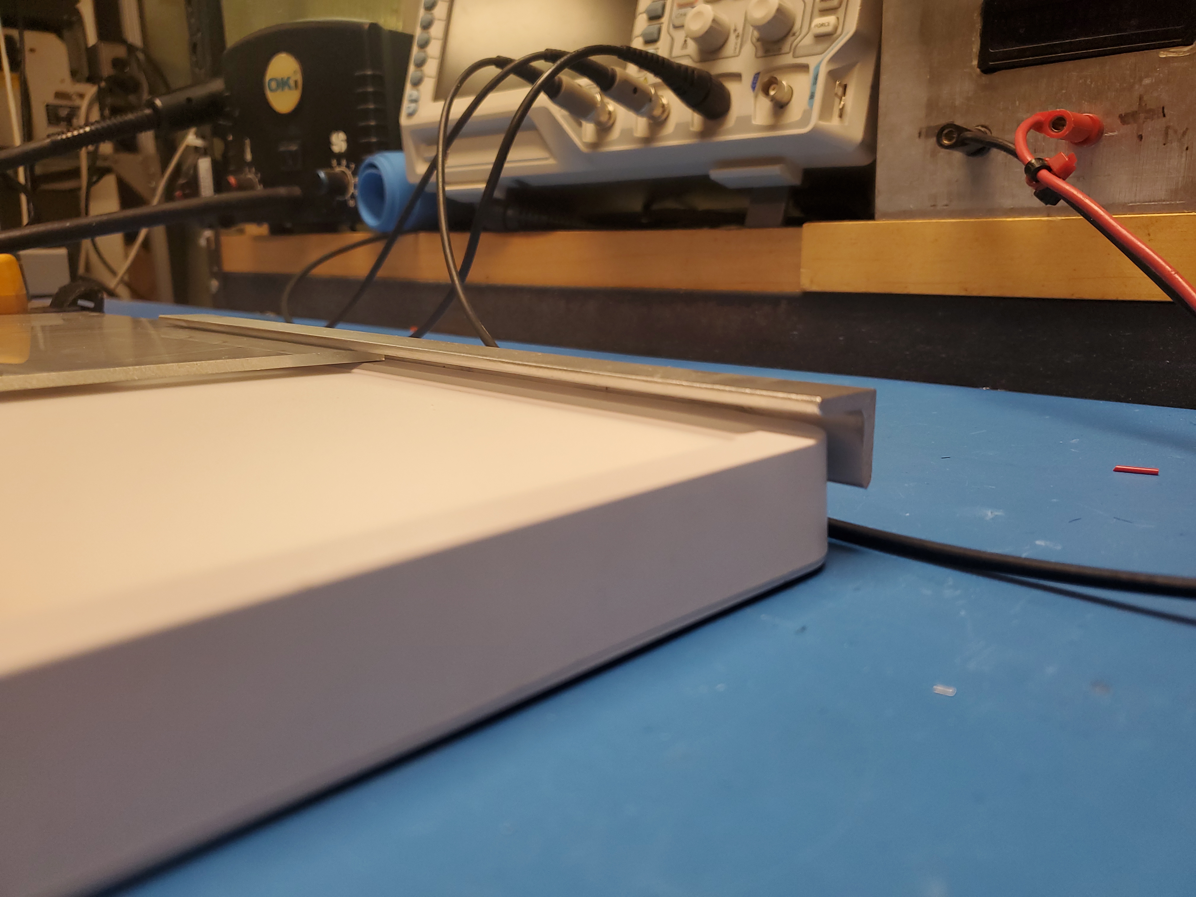 Finding some space for colored inserts. I was on the fence with how the red (pink) vs orange colored acrylic looked so I opted to make it removable. using some creative spacing and aluminum angle I made a top and bottom slide rail to insert the main sign and a color insert. To keep the inserts from coming out they sit in the small space between the light diffuser and the outer plastic bezel. Each diffuser is just band saw cut to fit inside that space. This ended up being so happily simple. If i wanted a more elaborate color gel effect, I could laser-cut the colored acrylic insert to allow for specific letters to be colored, while other letters remaining white or another color. Initially I was going to opt for mechanical fasteners, but 3M epoxy ended up working fairly well. I can update this with some self tapping plastites if need be, assuming they do not interefere with the led strips. Next up, possibly adjusting the current output of the existing driver? Scratch that the internal driver is pretty bad. Our 15W supply is a capacitive divider with a linear stage. This is hiding inside a plastic box with no thermal path out to the outside world. I was somewhat surprised it didn't immediately cook itself. I did like that there was some cable constraints preventing the mains input from getting yanked out, but it really looked like the power supply cavity was designed for a much larger board, and instead this little guy was shoved in. 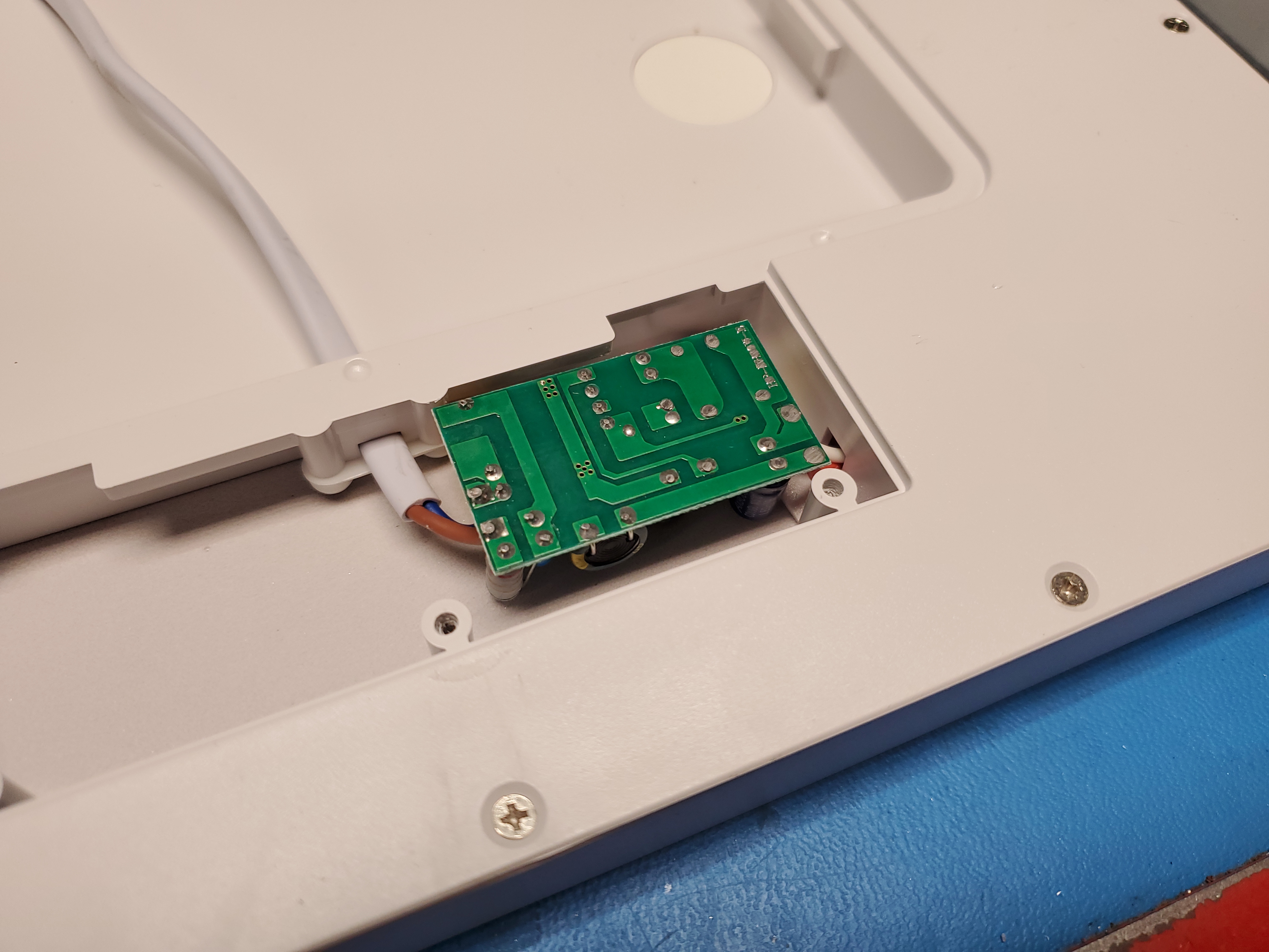 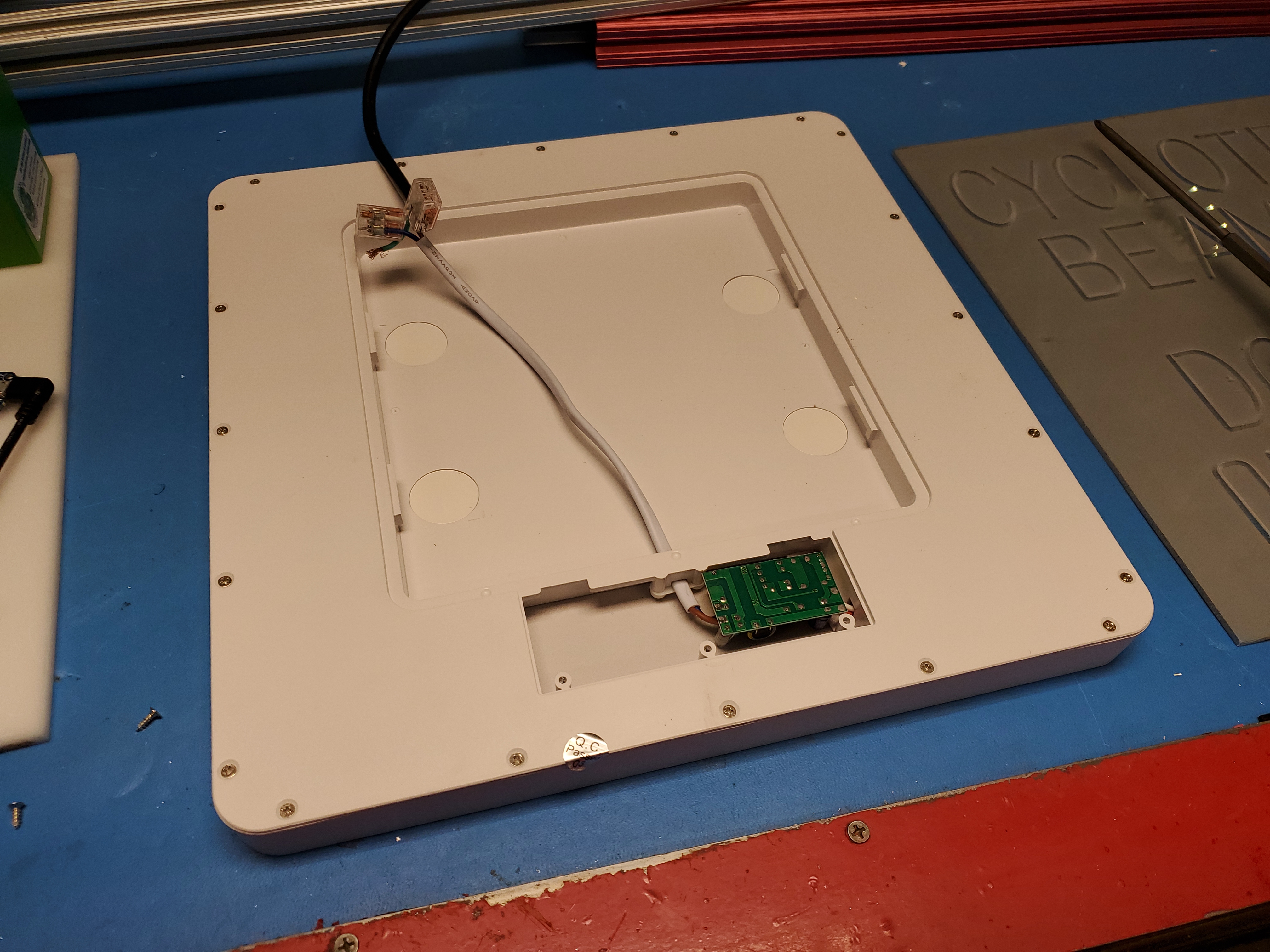 With the cover off it hovered around 180F [83C], so I imagine with the cover on, hiding up against a wall it was at least 90C. Given that there's an electrolytic capacitor and a linear regulator here there is no way this would run for more than a few months. Without brightness / current adjust and with this thing operating at 'start to deform plastics' temperature, it was time for it to go. With the supply running i measured ~67V nominal, which gave me a hint as to what operating voltage I would go for. LEDs are current driven devices, so its somewhat more useful to know the operating current, but given that I did not want to operate this nearly as brightly  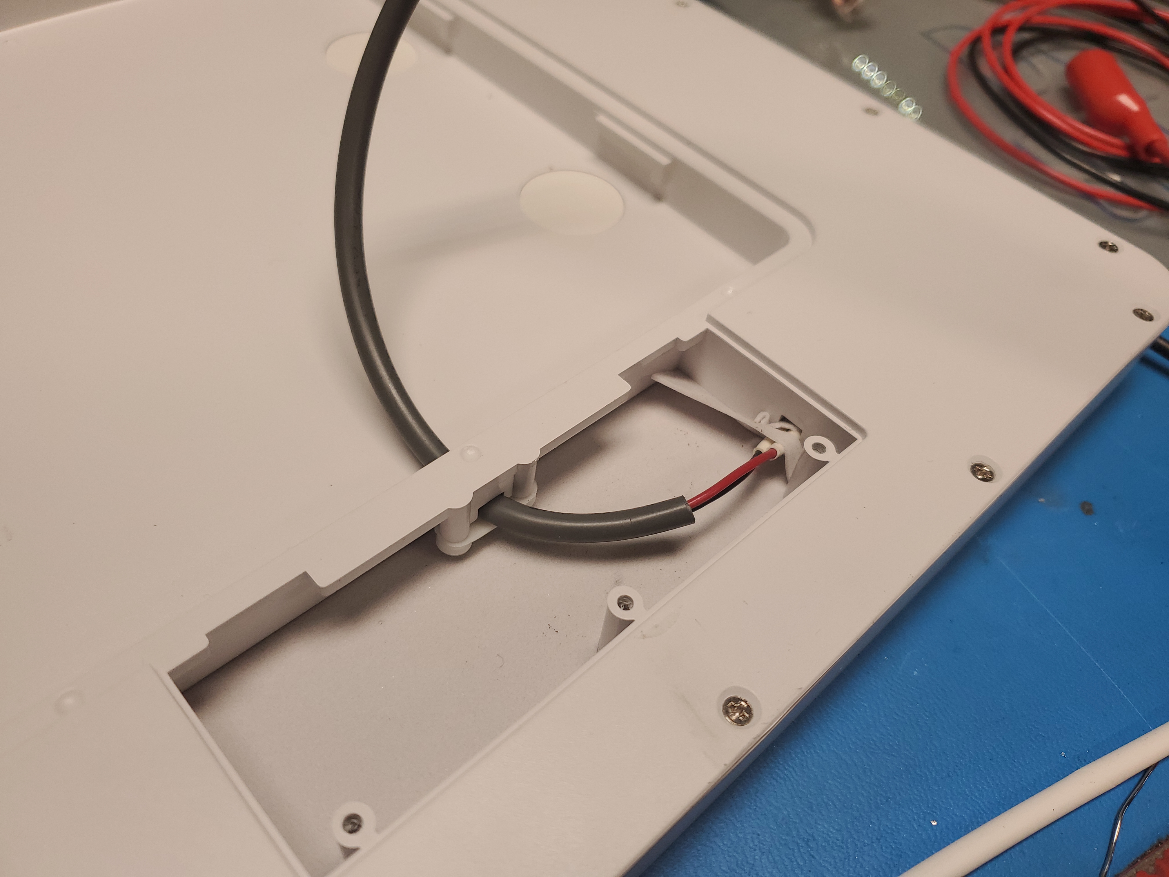 That was unexpected, here's a ~15 minute time-lapse. I recorded a visual of the supply itself because I somewhat expected it would 'rapidly disassemble'. The thermal camera used for this shot did not have optics that could resolve some of the finer details, but it was pretty clear the electrolytic cap was hot. While i couldn't find a temperature rating on it, its probably the most thermally sensitive item on the driver. Either way, 180F in an ambient ~75F environment, with the benefit of external ventilation. This is way too warm. Some assembly shots of the LED panel itself While the power supply is mediocre, the panel construction is not bad. Its single sided metalized PCB's connected in series, side illuminating a diffuser and reflector plate. Honestly not bad. There's no where for the LED thermals to escape to, but if the panel is being driven at a lower current this should not be an issue. 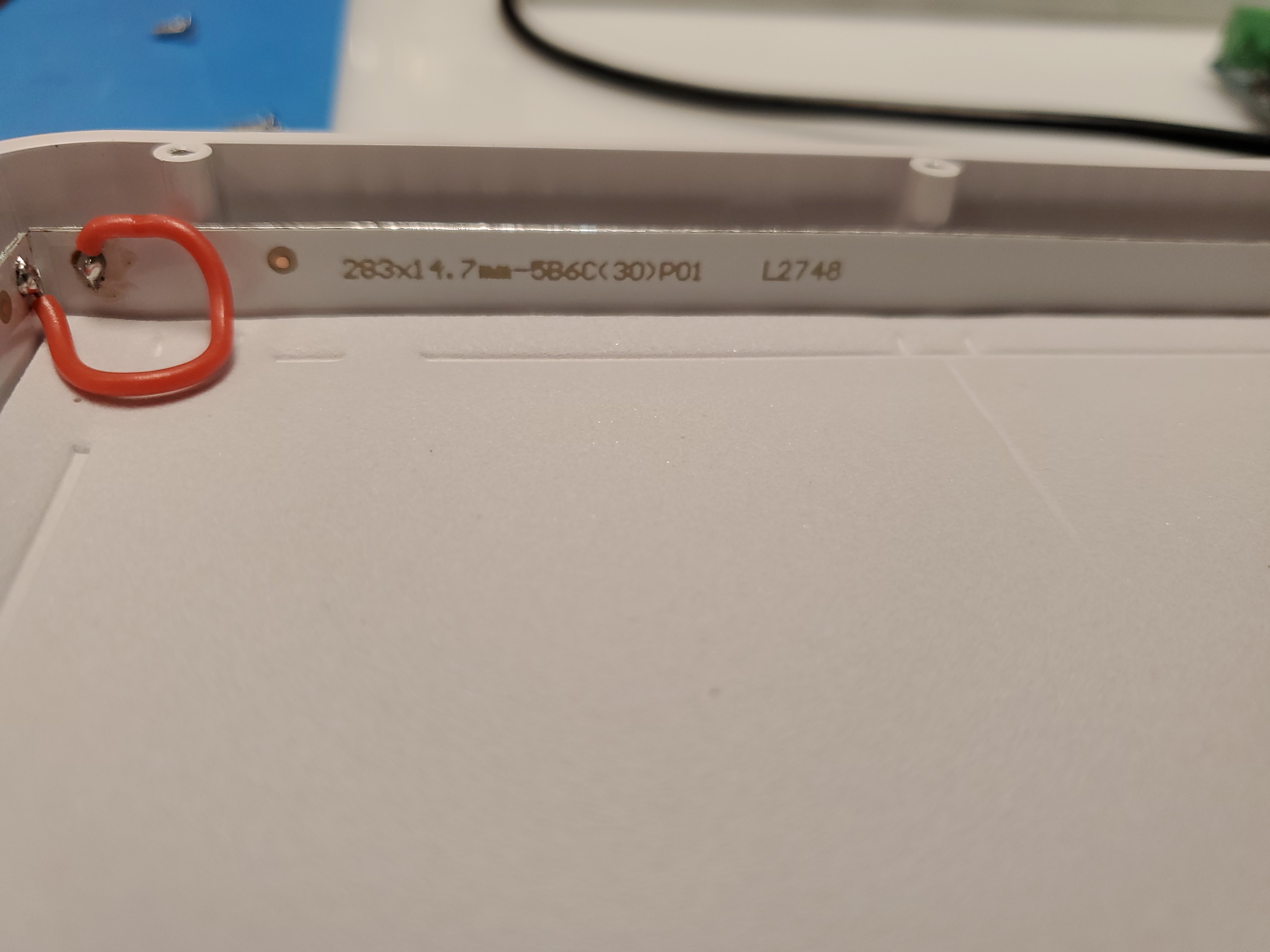 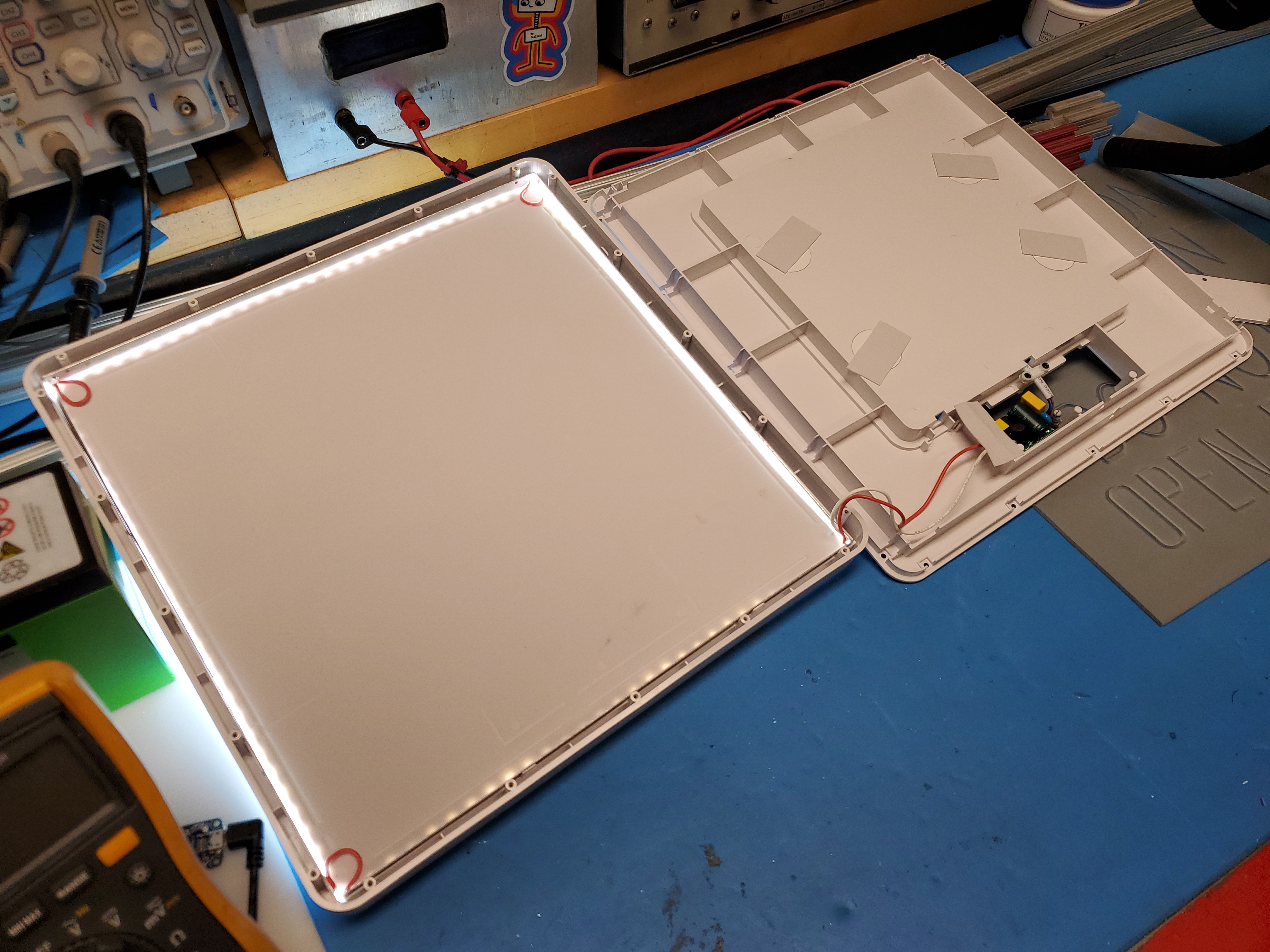 Meanwell, my favorite brand of LED driver I did try running the panel from a bench supply (60v) and while the LED's did slightly glow, I did need more volts. This is a weird application, I normally use LED supplies as battery chargers because, well the meanwell bricks are just fantastic, they are offered in IP68, and are incredibly abuse tolerant. This however is an odd one, I want 60-70V at 100mA or less, so time to explore the lower power meanwell offerings. I opted for a LDH-45A-350W [link]. This is a *boost* driver, IE it takes in 12v and creates 60+ volts for driving higher voltage strings. It also has external current adjust controls, all for ~13$ USD. Its small and looks up to the task. Lets look at the datasheet [link] [local copy]. 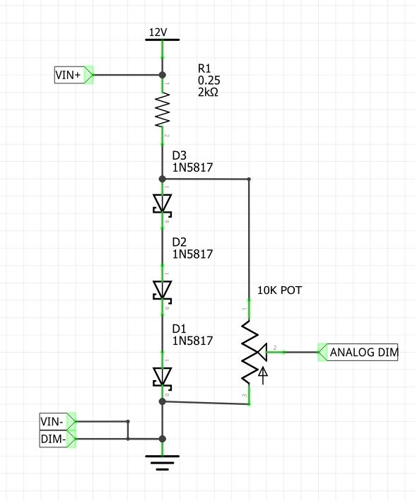 The analog input for the LDH-45A is 0.25 to 1.3v, so I needed around 1v for a signal voltage source to do this i used three shottky diodes, for ~0.9 -> 1.0V . This is tied into the main 12v feed so only one supply is required. In the simplest 'apply 12v and this just works'. So, nominally I could have a switch pulling ANALOG_DIM to ground for the off-state and then let it float up to the potentiometer set point in the on-state, if i was just driving with a mechanical switch. A quick analog-mode current adjust mock-up. There is an analog + PWM input on the meanwell, for some quick setup I'm opting for analog current control and a large 10-turn potentiometer as it was available in my miscellaneous stuff bin. It probably would be a bit more useful to display panel current but either way the boost voltage is visible. When the DIM input is disconnected it floats up to full output current, so having something as a boundary constraint for a current maximum is nice to have. One of the nice parts about this is only requiring a single 12v supply. With simple analog current adjust working, time to plot WiFi / ESP32 control The Meanwell has both an analog input *and* a PWM input. Its unclear what happens when both are driven. I'm going to guess the PWM is just R-C filtered internally and becomes analog dimming but worth a test on the bench. What hints to this for me is how there's a frequency dependency for the digital input, look at how 10KHZ differs vs 1KHZ. Either way lets see what happens if we give it conflicting inputs. For this I'm gonna just function-generator into the PWM DIM input. Ideally, if my manual 'switch is off' the ANALOG DIM is pulled low, so the PWM DIM would be active, and if my manual switch is 'on' it doesn't really matter if the PWM input is turning the light on 'more' 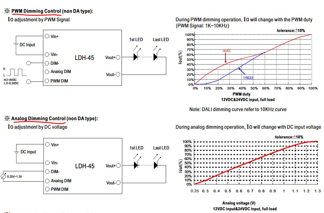 With simple analog current adjust working, time to plot WiFi / ESP32 control And it turns out the PWM and ANALOG inputs interact with each other.
Why not just use the PWM value and rely on the micro? Unfortunately this driver can put out a bit more than I think the panel is rated for, if i can use hardware to prevent this from happening (signal input bounds are literally defined by resistors) there's less likely an issue with its operation. It looks like a reasonable plan will be to feed the sign with a hardware switch for the input, when I want it manually selected 'on' the analog pot value will be piped to the analog DIM input, when I want the sign ff, the analog input is pulled to ground with a pull down resistor, and when I want it controlled by micro-controller the analog input is fed from a micro-controller RC, with a hardware limit on its brightness. In the case where the micro fails on, the resultant analog value will be less than the maximum the panel can tolerate. Super simple to implement, with a three position switch. How is this going to talk to Zoom Video Conferencing? I have never interfaced with Zoom before, so this will be an adventure. In your zoom account, there's this "app marketplace"? you have a few options, Webhooks OAuth and Zoom Apps. Webhooks are like push notifications, instead of polling something, it can yell at you when something changes. This reduces the amount of polled requests zoom gets, but does require your side of the fence to be visible (have a public facing address). Ah, this is why everything seems to want to use a 3rd party intermediary app, you need something public facing. By public facing this means that my little indicator light needs to be addressable on the public internet, or via a 3rd party who makes it accessible. Not terribly interested in either of those options. Here's there API-reference page [link]. Given that it will always change in the future, I will include some relevant snippets below. What we're mostly curious about is "Objects Actions and Events", specifically "User Activity" 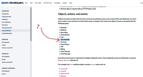 Next up, lets
check for some WebHook examples
I'd really prefer to not have to use a 3rd party to relay my Zoom activity just to turn on a light. Adafruit has some details on WebHooks [link] using their service, but lets see what else is out there. Is there an API reference I can poll instead? Technically I have a public facing web-server (this website) that could relay things, which is an option.  Looks like I
want "Presence Status"
So, I'm not the only person who wants a zoom 'I'm on the air' indicator light, however it seems like the easiest solution is to run a script locally and connect to your machine over USB, as shown here [link] and here [link]. My particular indicator light is 50ft away so lets go for something self-contained. If we check here [link] we have details on "presence status", we have: Do not disturb, In a Zoom Meeting, Presenting This is interesting, so I go and setup webhooks annnnd womp, I need a developer privilege. Dang it MIT. This is likely going to be annoying to get, the admin is likely inaccessibly buried in a quagmire of nonsense, so lets see what other options there are.  This looks
promising, eh maybe not
There's a really
interesting [link]
Toms Hardware posting on doing something really
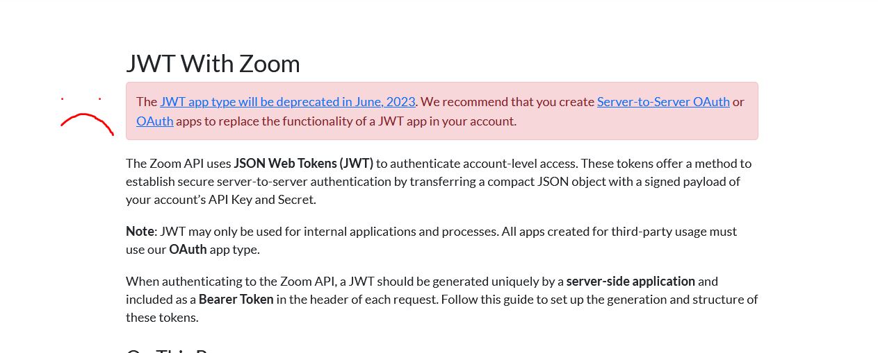
similar using a zoom JWT app, unfortunately Zoom has
started to depreciate JWT apps and MIT requires
account admin to permit it. I did learn from the Toms Hardware posting
about the python library 'zoomus' [link]
which is a REST API v2 wrapper. I really just want a
frigging API key so I can talk to zoom from
python.
 A related
project appears
Further digging found this [link] which points to.. again using webhooks which I again do not have access to. Time to check if MIT's IS&T will just grant developer access. Interesting the project above was a fork for teams-presence so theoretically if i was stuck using teams I could check both and update it. It does call the zoom presence indicator API which is in node js / javascript. Instead of re-inventing the wheel I'm gonna pause and see if the webhook / easier route is available, if it is, the plot is to start with either the Zoom Presence Indicator API [link] or adafruit's webhook project. If this is a no-go, I'm going to opt for an OAUTH route and use 3rd party services like here [link] 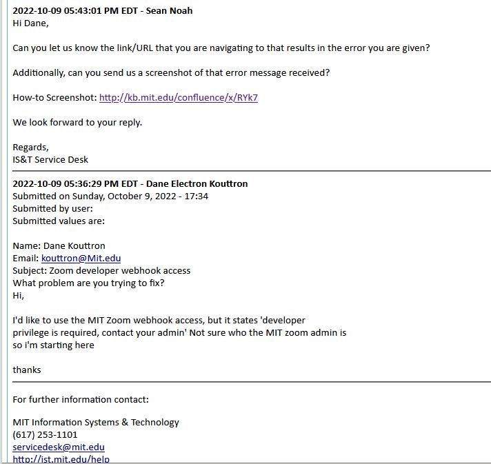 Getting
blown-off by MIT IS&T
Well that was to be expected, IS&T ghosted me for a week. Neat. Maybe I can cheat and just do a hardware (if webcam is on, turn on the outside sign)? That's do-able but man I'm more annoyed that I'm getting ghosted. 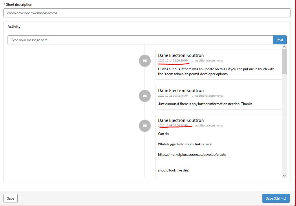 Plotting a
software overview
I don't really like scripts that run perpetually, but would rather have a script that can run as a Cron job. Cron can be set to run your script once a minute, once an hour, or anything in between. It should be important to check what zoom's rate-limiting is, but i doubt once a minute is too frequent. |
(There's other
photos in the photo gallery)
Concluding Remarks:- I should have used a lighhtswitch
If you have questions or comments, ask below or send over an email.
| Comments: |
|
HTML Comment Box
is loading comments...
|
Dane.Kouttron
Rensselaer Polytechnic
Institute
Electrical & Electrical
Power
631.978.1650