Dane.Kouttron
[6.22.11] ECHO 6: HK eco-6 Upgrade [Comms Upgrade]
| What? Acquired super low cost 6S lipo charger with balancing capabilities, added communications port to do quick data logging of individual cell energy during discharge & charge | 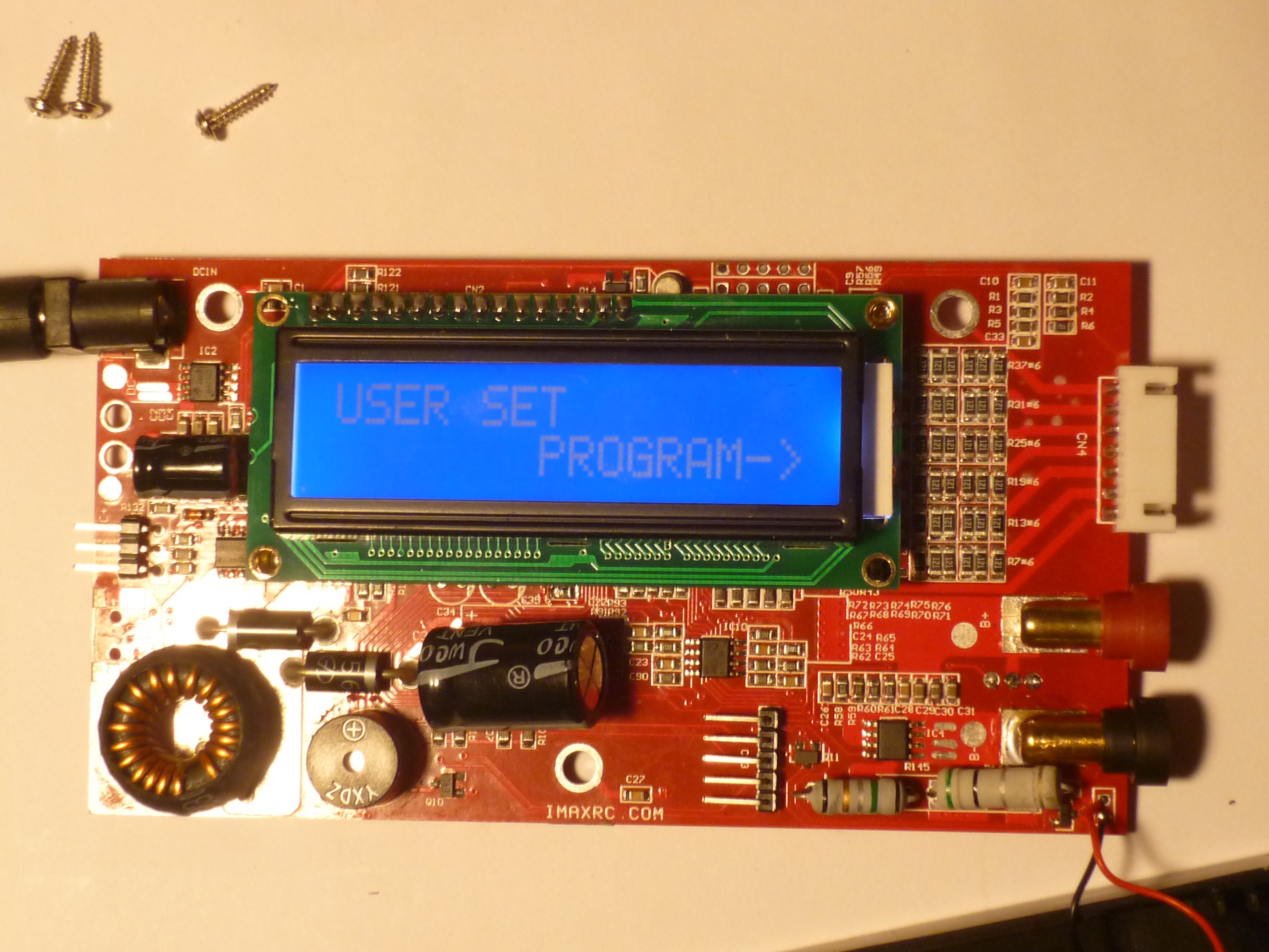 |
 |
| This project documents the re-purposing of a low-cost(17$) 6-Series multi chemistry battery charger/balancer, adding RS232 coms and providing interface plugins to a popular data interface applications. Taking a look at it's operation, its quirks, and what works well, will be fed into designing a similar, larger battery charger |
| What? | Components | How To | Results [DATA SETS] | References | IMAGE DIRECTORY |
| What? | Image/ Media |
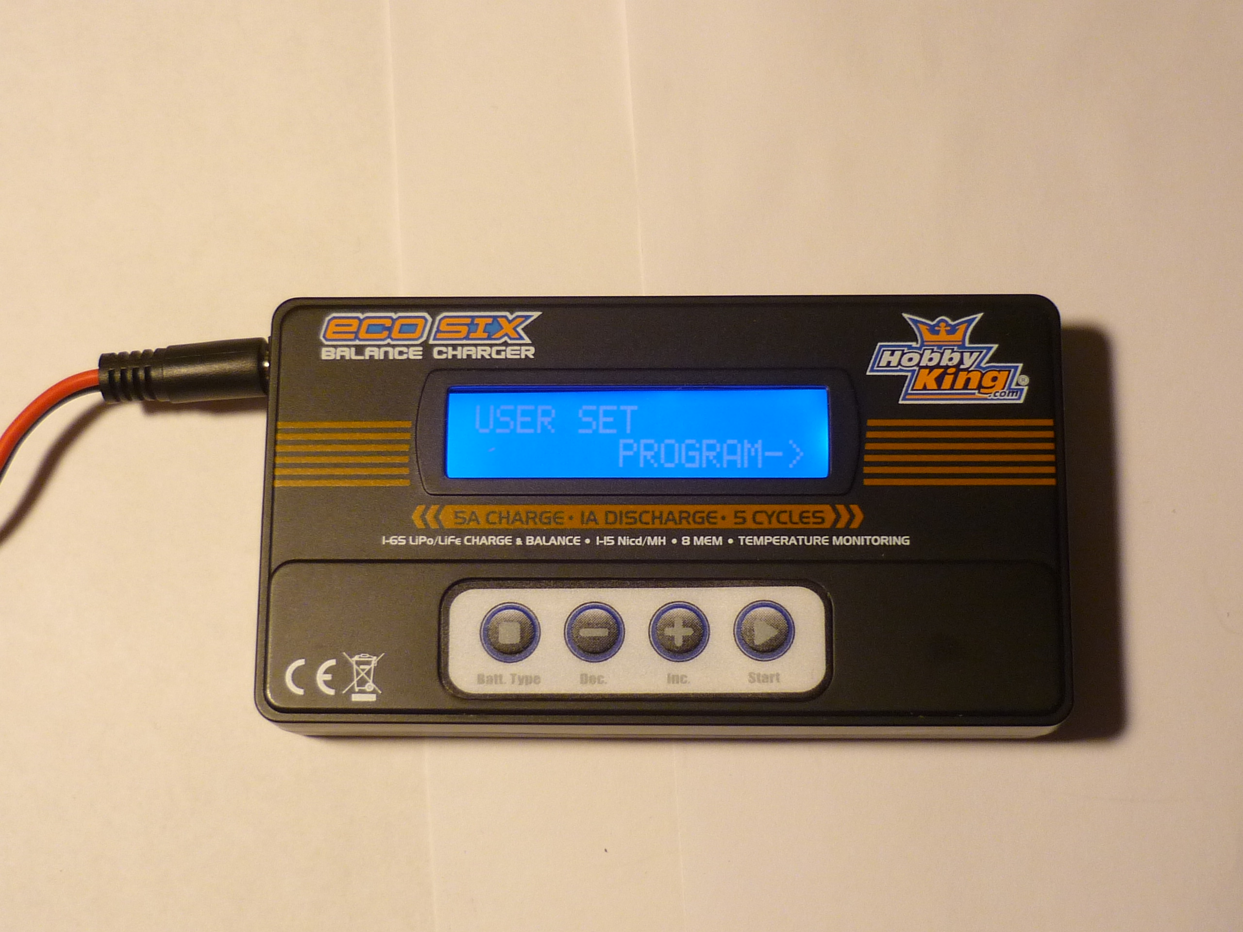
| This Thing: Hobbyking Echo 6 50W ChargerIs pretty interesting. 17$ and you get a 6-Series multi-chemistry cell charger [5A] / discharger [1A]. Wouldnt it be nice to see a cell charge, checkout how its being charged? Keep a log of individual cell performance? compare capacity between a new cell and one youve beaten up with an RC car ? The goal of this run-through is to do just that. |
  |
| What do I need to make this work | Image/ Media | Image / Media |
| Eco-6
Charger or equivalent Hobbyking Echo 6 50W Charger Spec'd at 6S max, 5A
charge, 1A discharge. Super low cost,
|
 |
 |
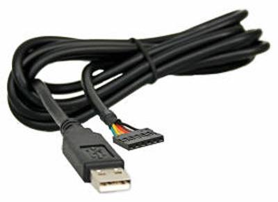
| FTDI->
RS232 to USB cable,
or rs232 level shifter (or 3v3 RS232 to standard rs232 -> computer) |
 |
 |
| How to: | Image/ Media |
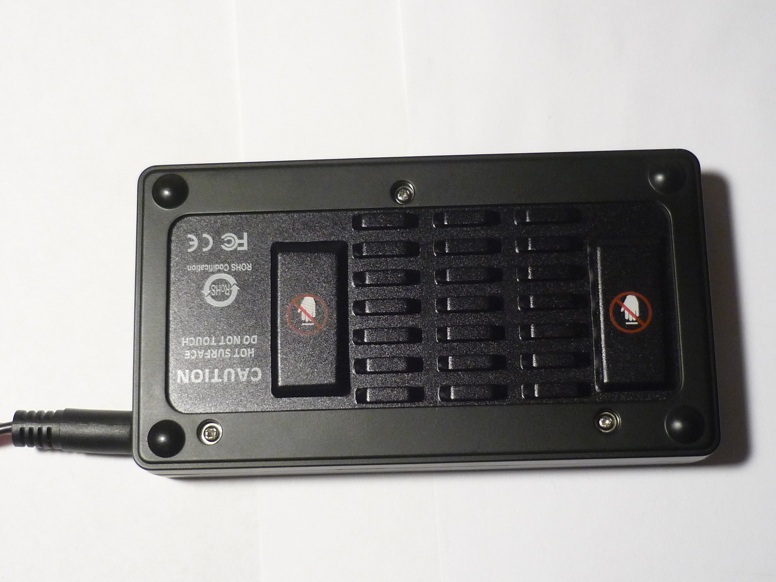
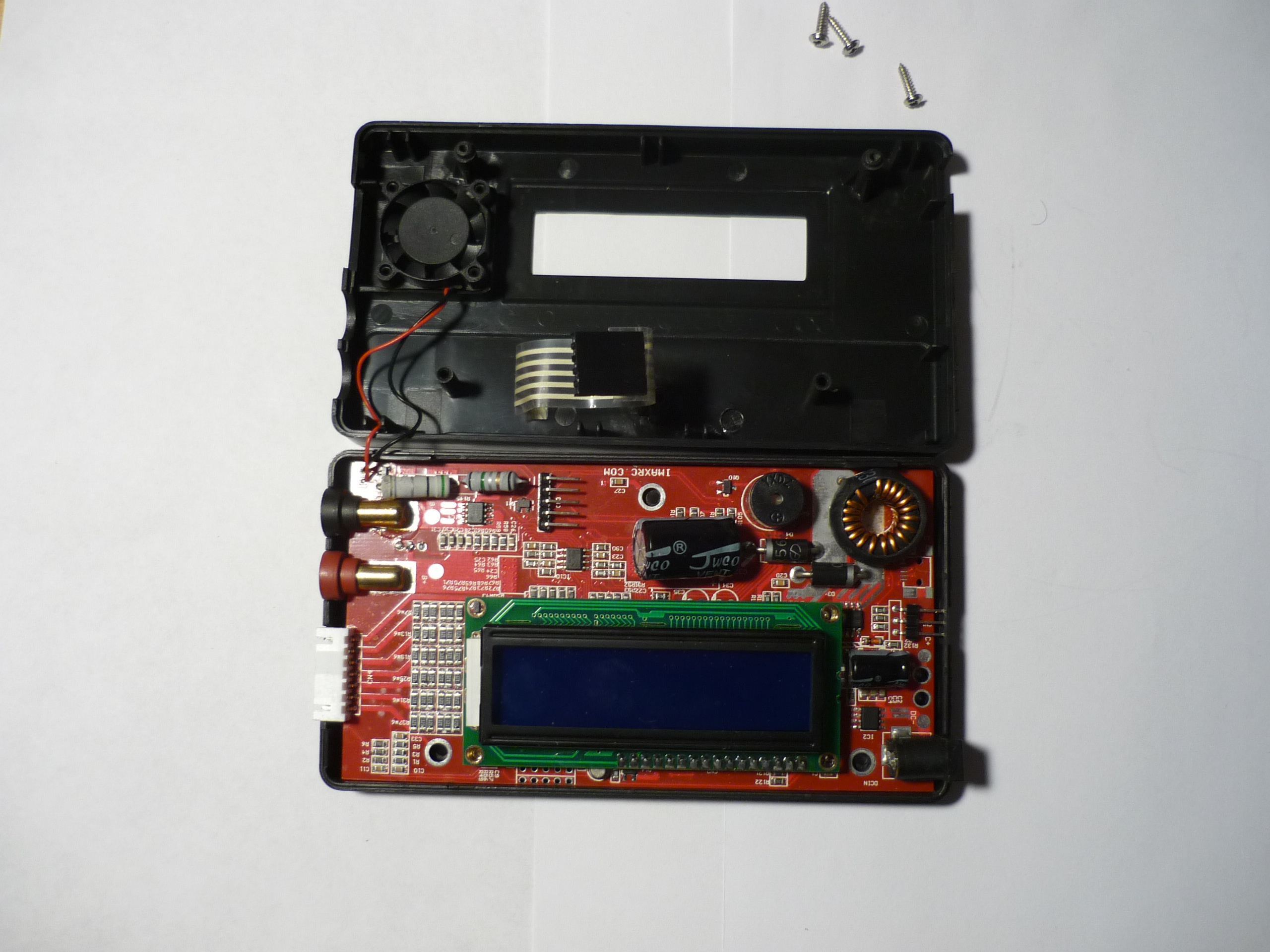
| Open it
up Start unscrewing the 3 bottom mounting screws with the charger off. Get to the PCB, removing the mounting screws between the case, the mosfets and the board. Be careful of ESD, and bring out the pcb, verifying quickly that it still powers up (using separate 12V supply) |
 |
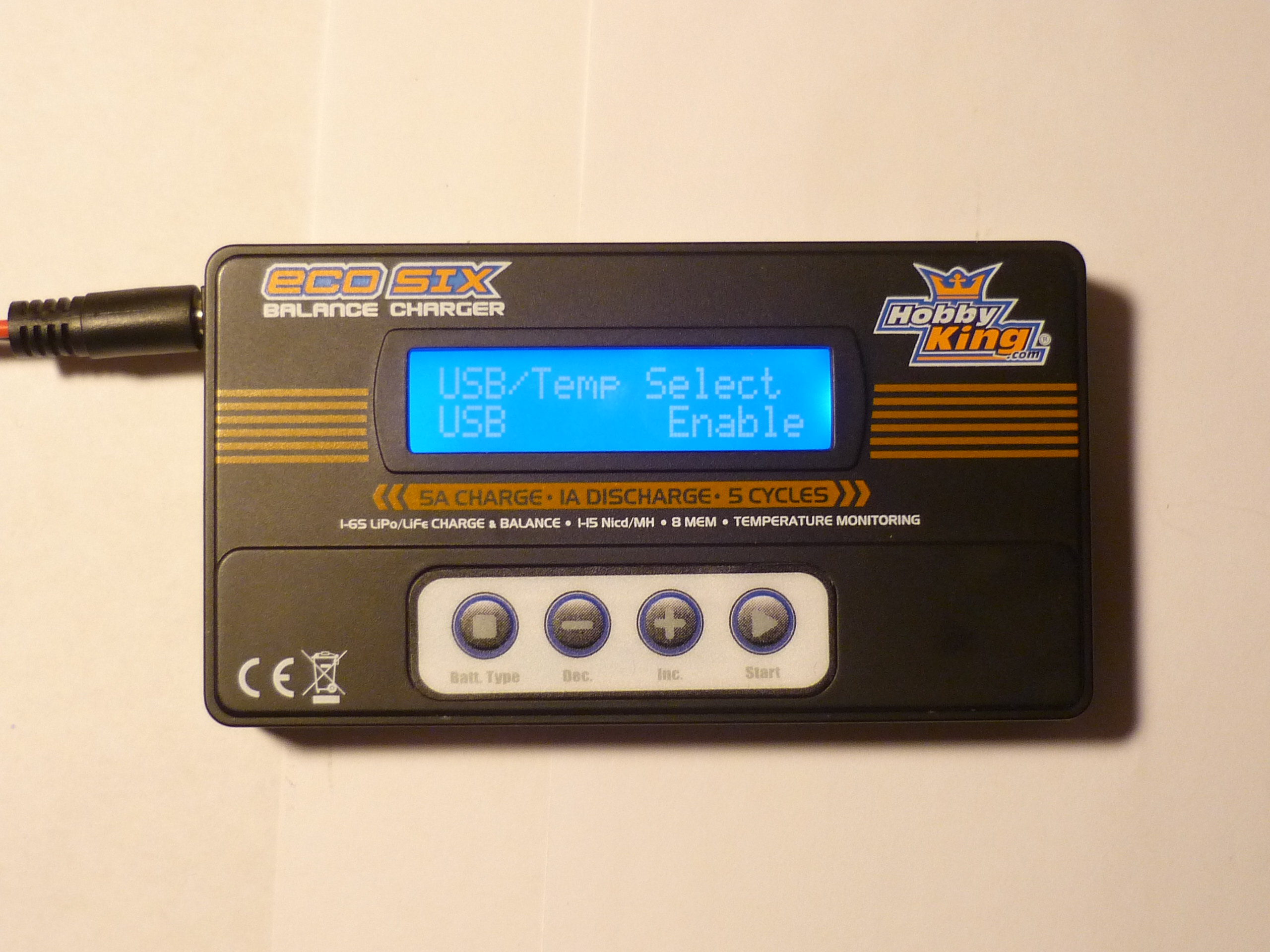
| Enable
USB? i noticed, while toying with the menu's, That there was a USB enable mode. That nice, however, there's no USB port. It led me to believe, for the sake of simplicity, the firmware running on the eco-6 was a copy of a larger unit, that supported USB. Ok, that nice, but what the heck I'll enable it, see where it goes. |
 |
| Find MCU Transmit I noticed that the micro-controller running the show, was an atmega32. I pulled up the datasheet, noticed it had a UART (transmit and receive for rs232), Tapped a scope probe on it, and lo: it suddenly jumped to life. I traced it to the back of the board, to a no-pop area (where an FTDI rs232->USB converter IC wouldve lived, it was de-populated. |
 |
| Oh
hey, there's a Semi-Jtag Interface there's a strange jtag-like interface on top of the board, however it appears only sck and rst are routed. Top row of connections is system gnd, aside from the far left pin, which is tied to a gpio. |
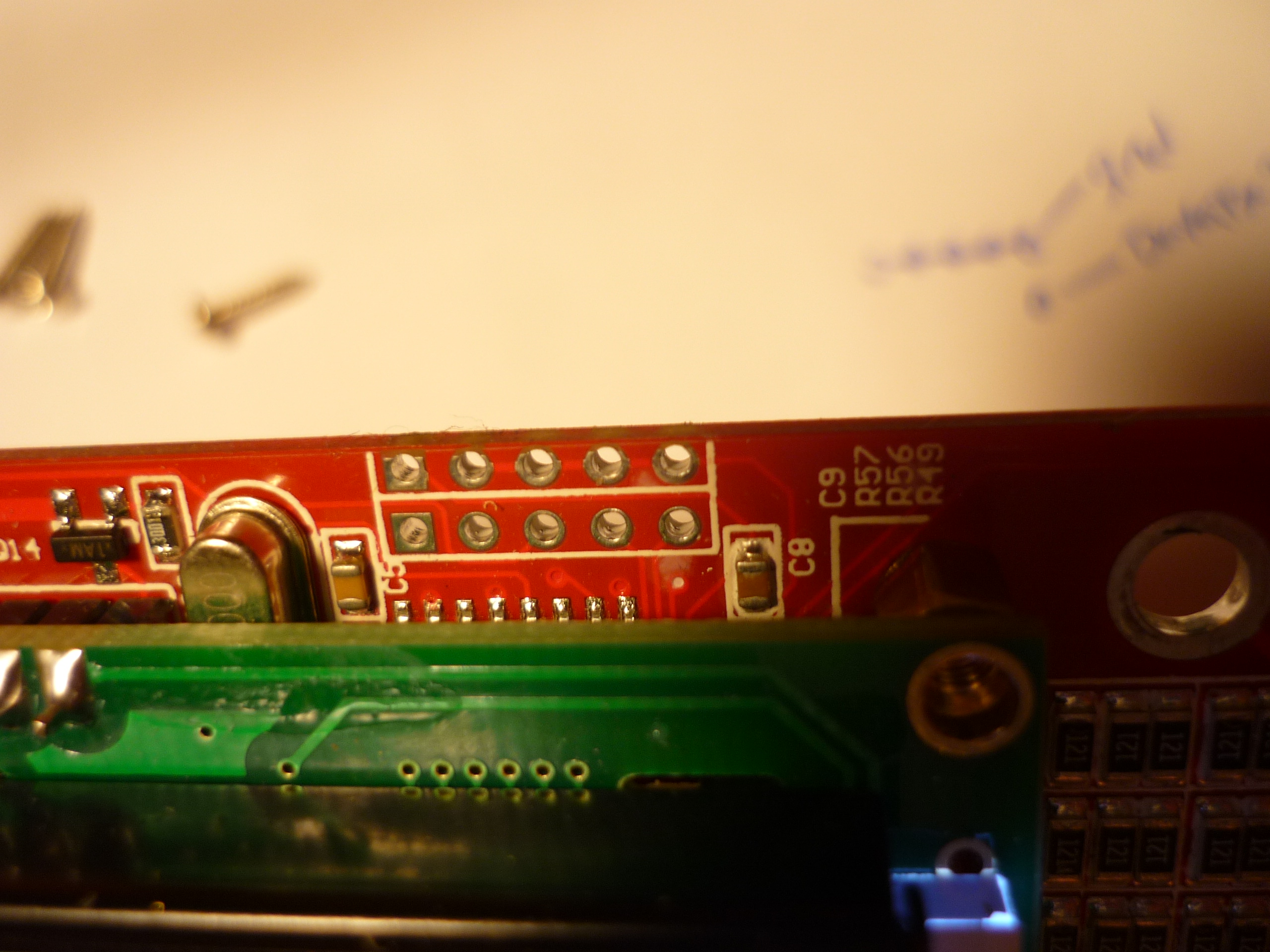 |
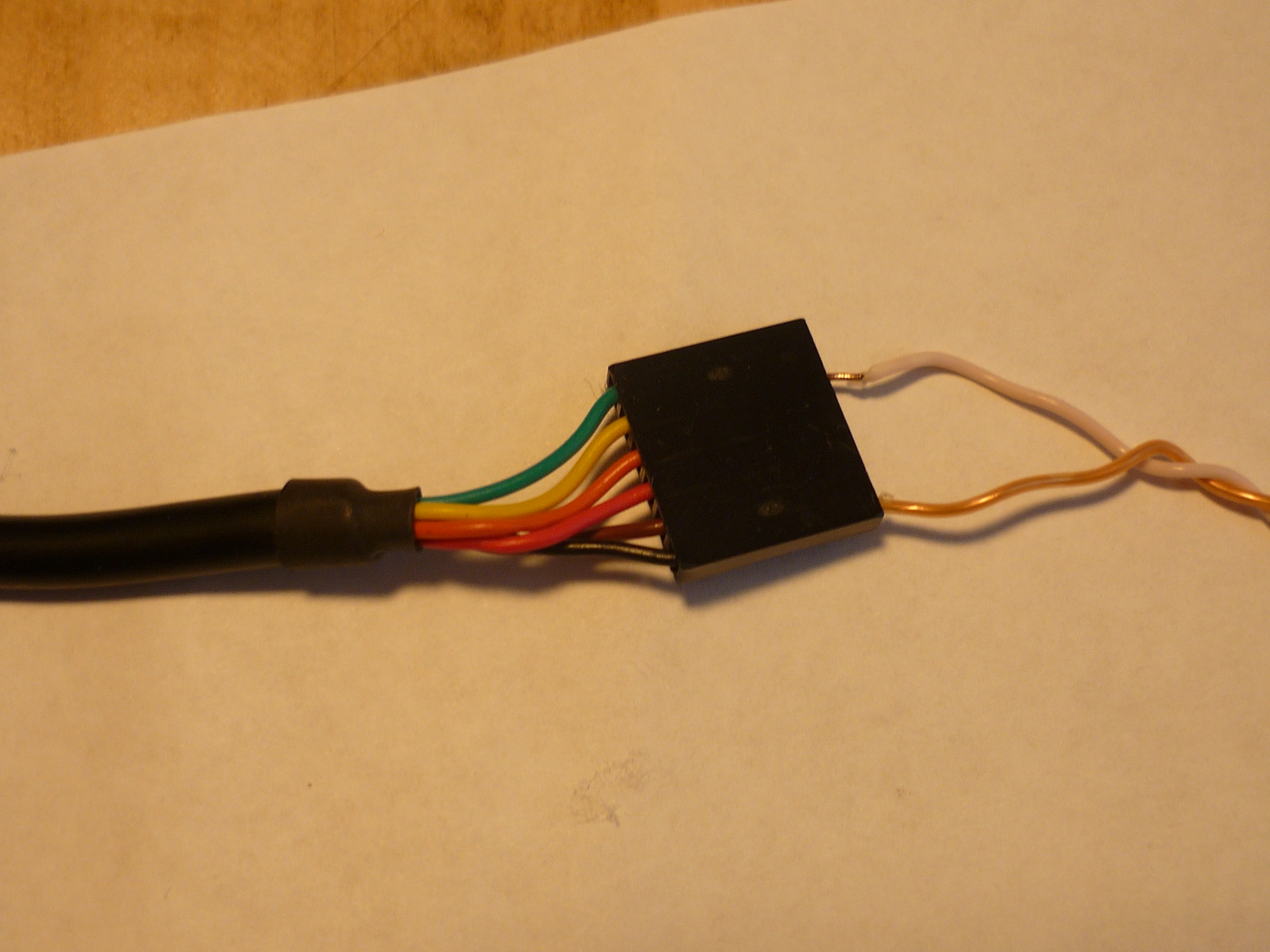
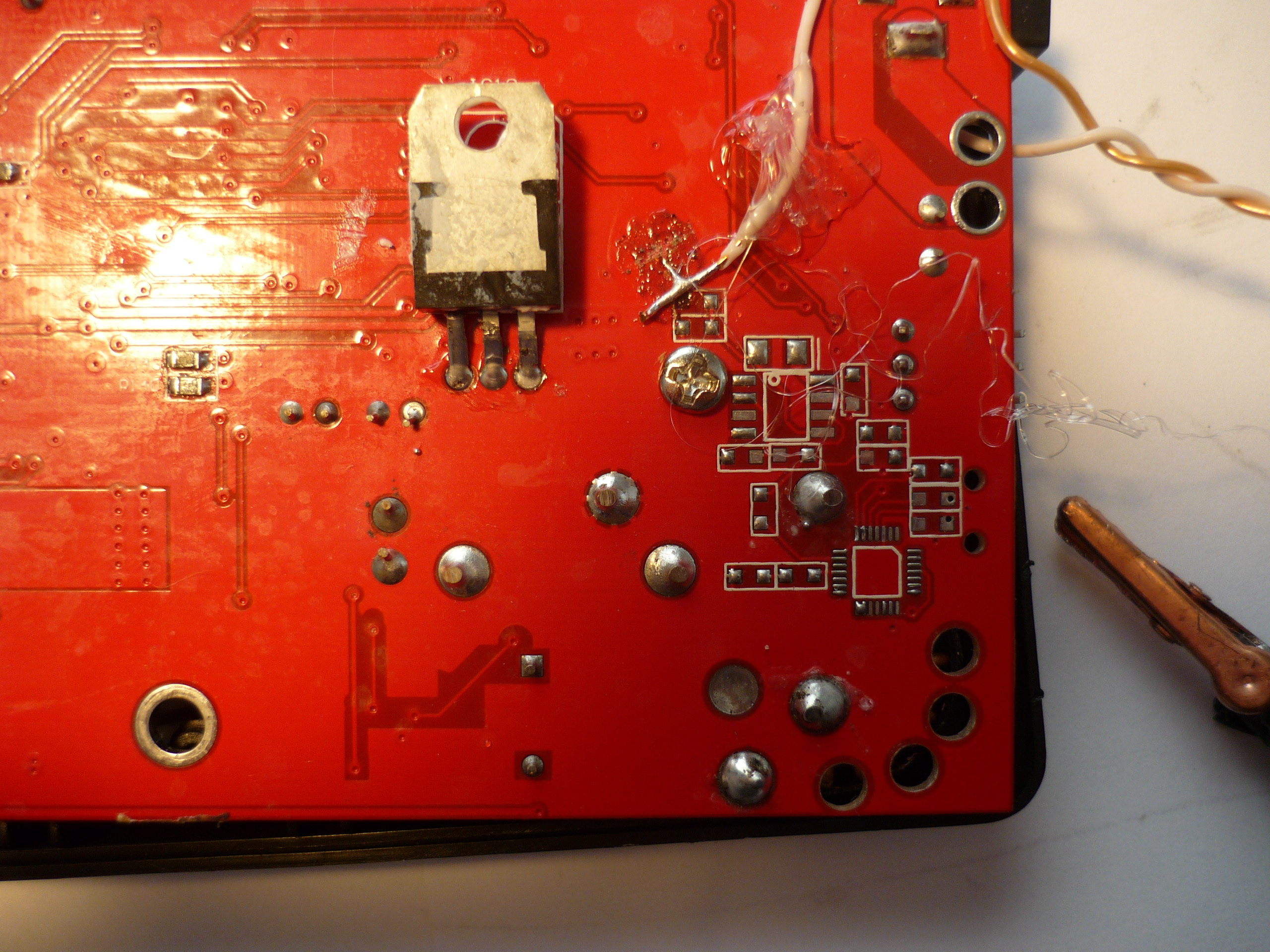
| Looks
like An FTDI chip would live here: On the far right corner, is a pad for an FTDI, or similar, USB-> rs232 adapter. Everything is non-populated, hinting that this board is used in another product, with higher current capability, and a better coms interface. There's a resistive divider coming from the micro controller TX, into the RX of an FTDI pad. I tapped (with an absurdly wrong-sized 22 gague wire) on the tx from the mcu and 'strain-relieved' the connection with hot-glue. I tied the white wire to the tx pad, (easiest accessible location for pulling out the mcu rs232 ttl transmit). TLDR: i need to invest in some 30 gague wire :) |
 |
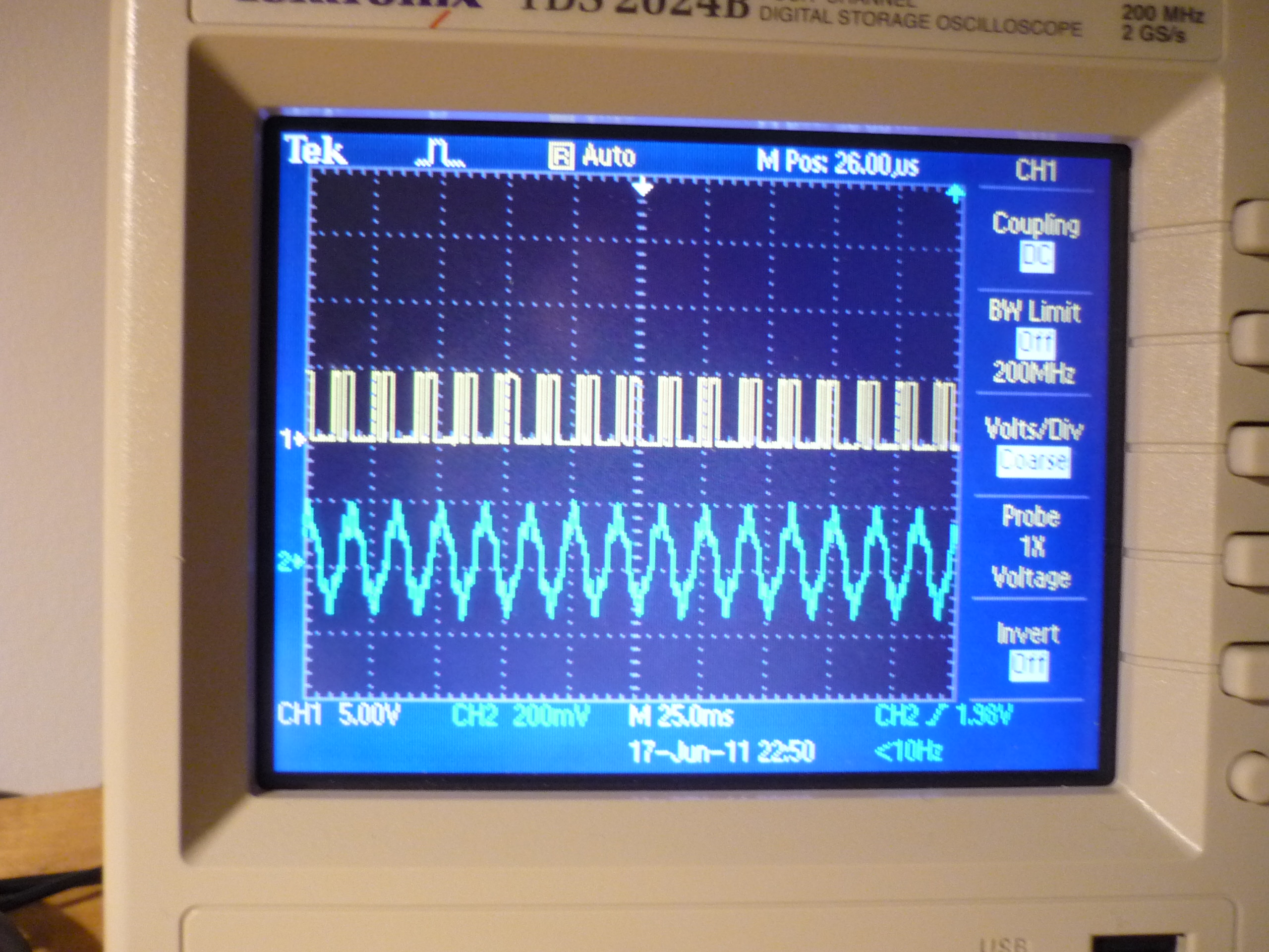
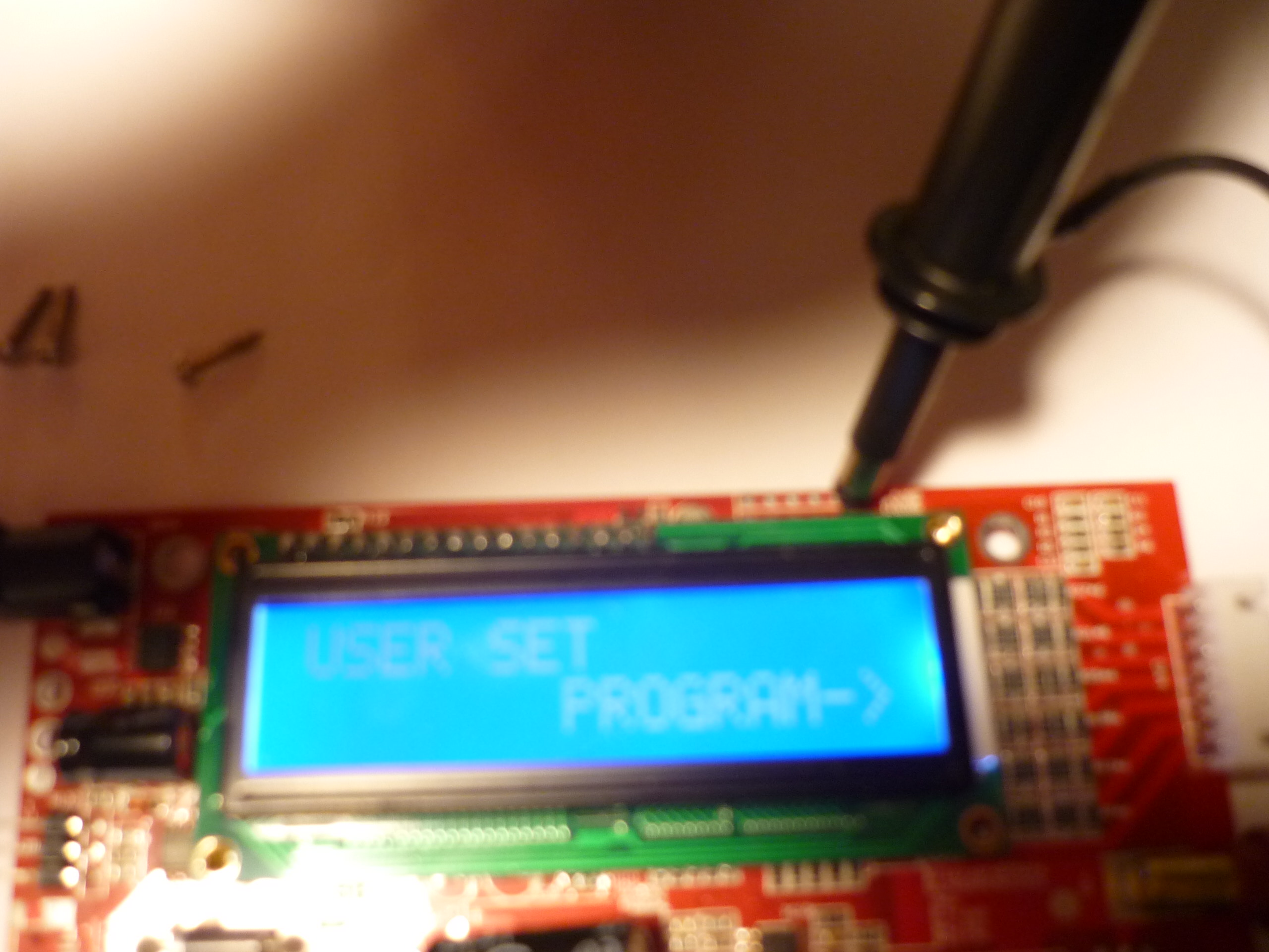
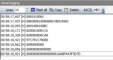
| Binary
RS232 TTL Datastreem AHOY. Shown in the scope capture, above, the micro was running 5v ttl rs232, and i luckily had my FTDI 5/3v3 ttl -> Usb cable floating about. Upon tying in charger ground and charger tx to the ftdi cable RX, and opening up a serial port terminal, (i started with 115200 baud, and worked my way down to 9600), i was getting DATA |
|
| SOUNDS
LIKE DATA The idea that this board is used with a different population option for more functionality, indicated that the coms protocol should be similar to an existing, more functional product. pulling up putty, at 9600 9N1, the datastream looked repeating, i pulled up miniterm, and set the output to binary parsing instead of ascii, and lo, non-garbled data. Initially i thought it was odd that the data came in repeatable chunks at 9600 9N1, versus 8N1, but it turns out it was miniterm/the ftdi cable i was using just getting confused |
 |
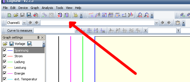
| Piping
the data into LOGVIEWGrab
a copy of 'LogView' from the following: (make sure to select english, if you don't speak german!)http://www.logview.info/vBulletin/downloads.php Install/select the following INI http://transistor-man.com/files/echo-6/config.ini |
|
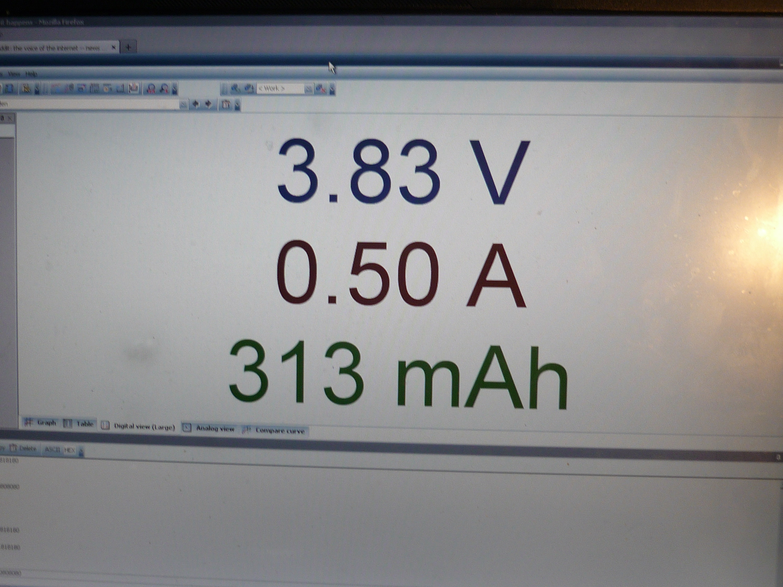
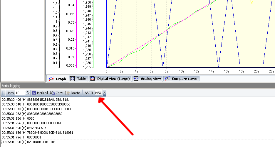
| Get
it to RUN! With the FTDI cable plugged in and the correct com port selected, select the green 'com' button. If the correct INI file (available above) and the program is connected, there should be a stream of data available. (check the red arrow) Logview allows for a number of customizations as well as data output formats, its a really excellent piece of free software. |
  |
| Kelvin'ing
(sort of) Attach the balance connector (tacked from large 6 pin balancing connector) to the cell at an 'unloaded point' The charger bases its decisions (for single cells) on the main power lead voltage. As there can be ~5A flowing through these cables, the voltage observed at the charger is equal to: (cell voltage - [I Charge * R Cable]) so the measurements and cut-off points arent very accurate, however, the balancing connector also has an adc that's constantly monitored (1hz) attaching the balancing connector to the cell before the point where the charge/discharge cable connects provides a more accurate, unloaded measurement. |
|
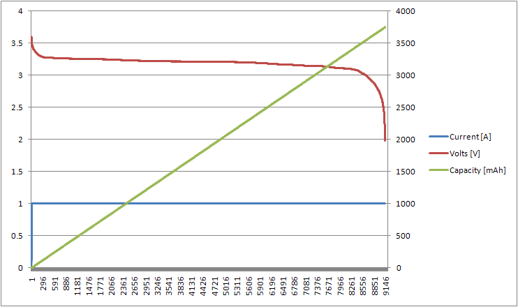
| Sample DataSets | Graph | DataSet |
| [Aged] Lithium Iron Phosphate 4 AH cell, [1A discharge] 2V cutoff threshold |
|
Data Set |
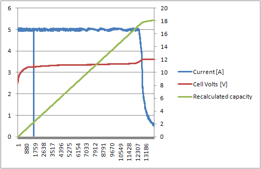
| 3
Yr Old Paper Tube Lithium Iron Phosphate 2.2 AH A123 26650 cell [5A charge] |
 |
Dataset |
| Single
Scooter Pack block, 9P 26650 5A charge plot
|
 |
Dataset |
(There's
other photos in the photo gallery)
Concluding
Remarks:
The eco-six multi-chemistry charger/balancer/discharger is great for the price, but it has some drawbacks. It would be excellent if it were able to use the balancing connector to provide a kelvin'd measurement point on the cell in test. Without making a kelvin'd connection to the cell's voltage, the cutoffs are completley artificial, as 100mv of loss in the cable between the cell and the device can contribute an error margin upwards of 10% SOC. This is visible in the datasets above, specifically if you look at the delta between the observed balance connector voltage and the charger voltage measurement.
if you have questions or comments, shoot over an email.
References:
Wikipedia: Lithium iron phosphate batteries: http://en.wikipedia.org/wiki/Lithium_iron_phosphate_battery
HobbyKing Discussion: Some faint info on the eco-6: http://www.hobbyking.com/hobbyking/store/uh_viewitem.asp?idproduct=11060
Manual: Copy of similar manual
| Comments: |
|
HTML
Comment Box
is loading comments...
|
(be
careful, im not responsible for your exploded battery pack)
Dane.Kouttron
Rensselaer Polytechnic Institute
Electrical & Electrical Power
631.978.1650