Dane.Kouttron
[11.10.21] Mantis Drone Upgrades and add-ons
| Documenting the
undocumented features of a cheap, awesome, fold-able
drone: TLDR: I found an amazing, <200$ fold-able quad-rotor, that is full of hidden open-source hardware and even talks mavlink Follow along, snoop some communications, get up in the air, build a battery, make a neat carry case and capture some data! |
| What? |
3D
Printed Drone Case |
Controller
Hard Case |
Battery Teardown | Mavlink
& Mission Planner |
Conclusion | Image Directory |
| Project Background |
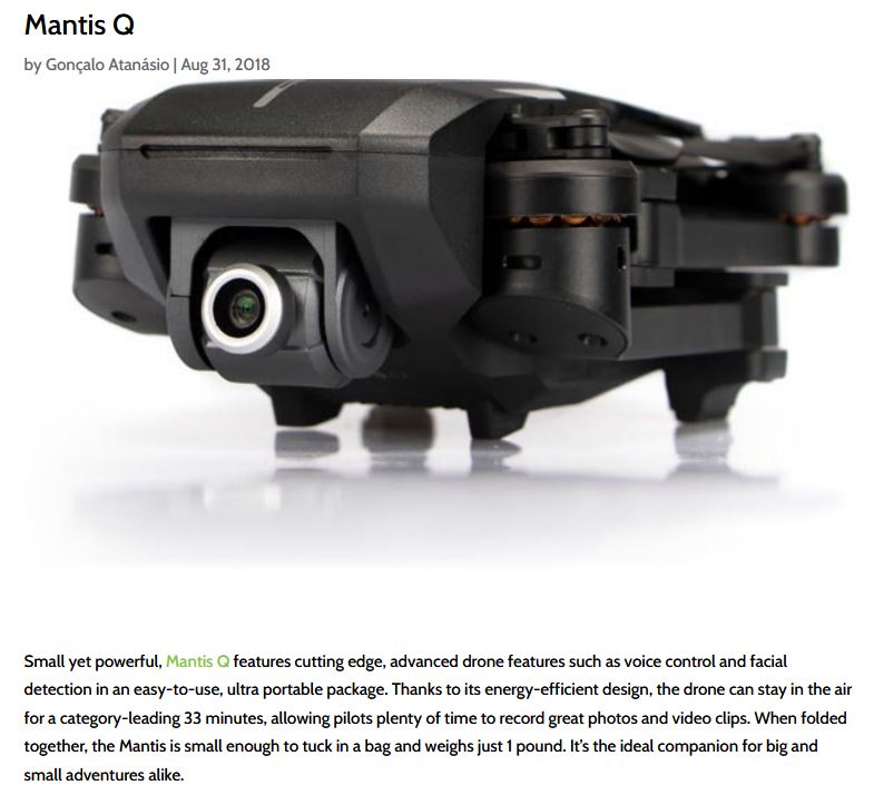
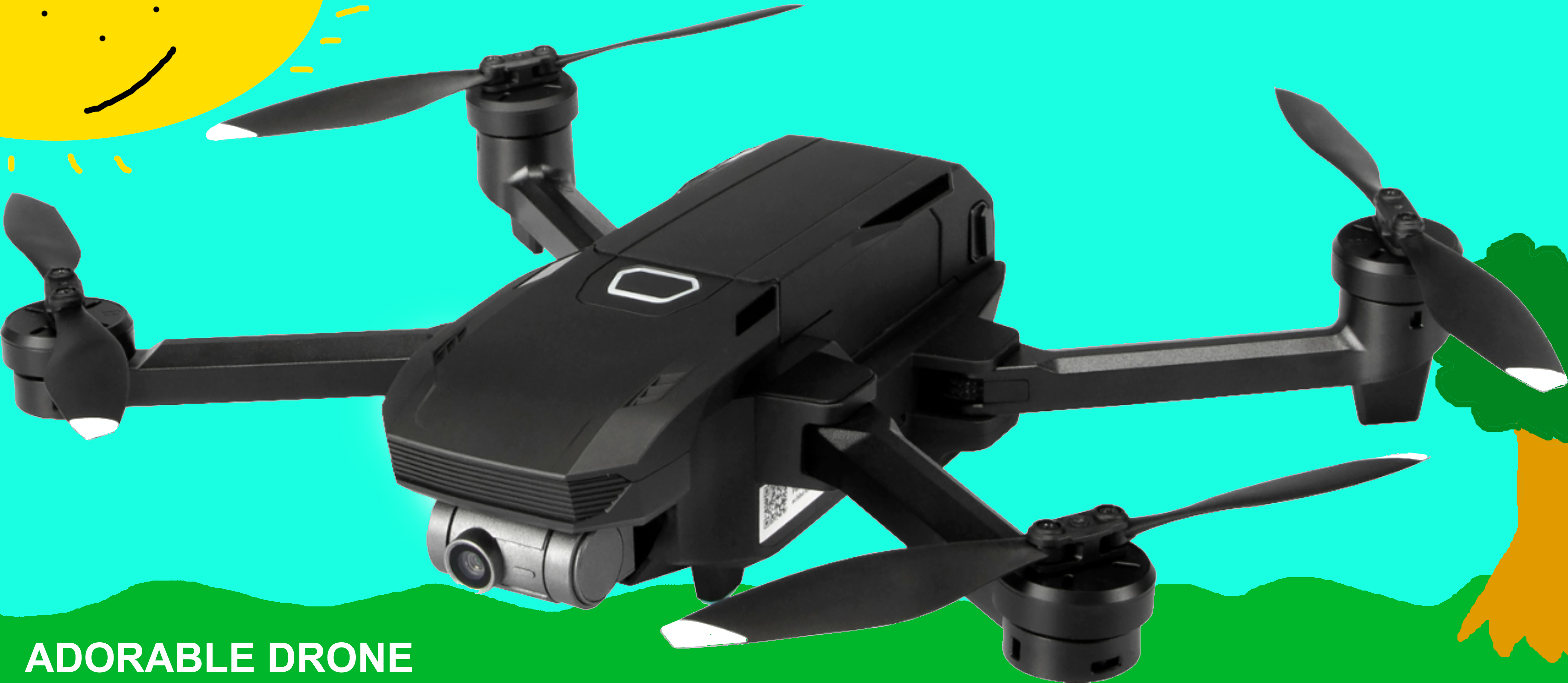 I'm a big fan of the Mantis G drone,
it purportedly uses a pixhawk, its incredibly
small and the video footage is amazing. There's some
things that would make it a bit better though and I'm
detailing them below. "Dane why didn't you get a DJI",
good question, but nominally: they are remarkably
black boxes, they have their own undocumented
telemetry and communication protocols, and none of that is
really compatible with open-source activities. Want to
test out a new sensor? nope, want to do something that the
DJI app says no to? nope. The Mantis contraptions appear
to at least be based on the pixhawk / open-source
ecosystem, enough to allow some sorting out of telemetry
and communications. I'm a big fan of the Mantis G drone,
it purportedly uses a pixhawk, its incredibly
small and the video footage is amazing. There's some
things that would make it a bit better though and I'm
detailing them below. "Dane why didn't you get a DJI",
good question, but nominally: they are remarkably
black boxes, they have their own undocumented
telemetry and communication protocols, and none of that is
really compatible with open-source activities. Want to
test out a new sensor? nope, want to do something that the
DJI app says no to? nope. The Mantis contraptions appear
to at least be based on the pixhawk / open-source
ecosystem, enough to allow some sorting out of telemetry
and communications. Some details about PX4 and Mantis here [link] |
 Some quick notes, It appears the
Mantis G and Q are mechanically identical, aside
from a better gimbal on the 'g' model. I honestly had not
heard of the company, but I found out about them when I
looked thru pix-hawk forums digging around to see what was
supported. Interestingly Yuneec is kinda similar in
approach as 3d Robotics. I have a 3DR solo, one of the
first big open-source pillars of drones. The mantis Q
(lower end model) was released for 499 USD in late 2018,
at the time of this writing they are ~200 USD on
eBay. It looks like the mantis G was a much smaller
release, possibly due to the 2020 chip shortages or the
like, it's about $ 400 on eBay as of late 2021. Some quick notes, It appears the
Mantis G and Q are mechanically identical, aside
from a better gimbal on the 'g' model. I honestly had not
heard of the company, but I found out about them when I
looked thru pix-hawk forums digging around to see what was
supported. Interestingly Yuneec is kinda similar in
approach as 3d Robotics. I have a 3DR solo, one of the
first big open-source pillars of drones. The mantis Q
(lower end model) was released for 499 USD in late 2018,
at the time of this writing they are ~200 USD on
eBay. It looks like the mantis G was a much smaller
release, possibly due to the 2020 chip shortages or the
like, it's about $ 400 on eBay as of late 2021. |
Here's my
wish-list of improvements:
|
<I'm trying a new format with more animated video clips, bare with me I'm sorting out what works well>
| Making a hard-case for the
drone |
|
So here's the most recent cad model, for my personal case I opted to add in an email address, which hopefully (fingers crossed) will help if this gets lost. I opted not to cad-in the Velcro loop strip because, well, its a floppy material and Solidworks is fairly bad at floppy things. List of McMaster-Carr parts used:
|
|
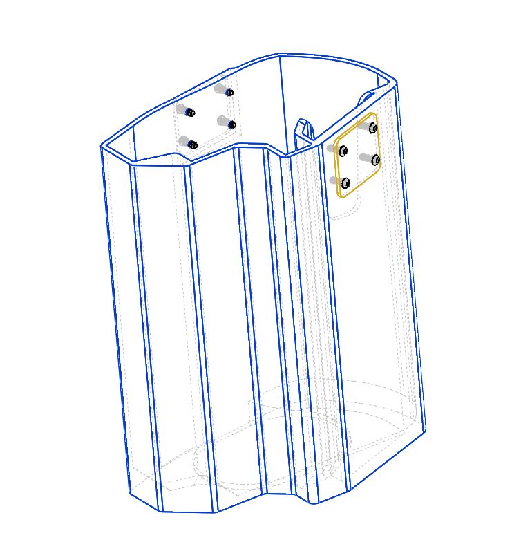
Cad
model view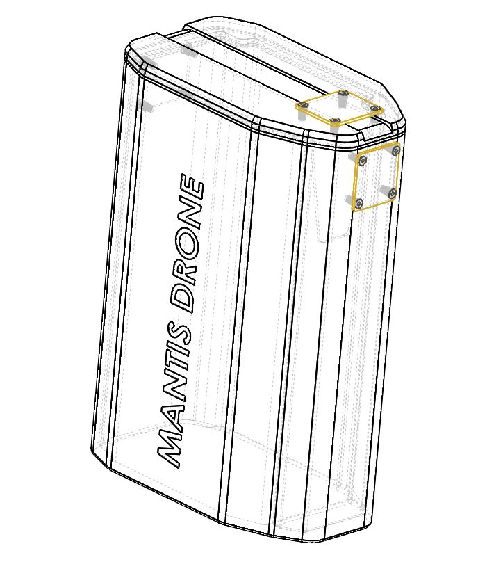 Here's a somewhat-see thru model of the final cad variant, the goal here is to be small enough to fit the drone, have the space for a Velcro strap and some mounting hardware to allow for a somewhat-lockable lid. The three plates friction fit the velcro strap to the case and make sure the lid does not get lost. These attach to the case with my favorite lil thermal inserts using M2 screws. M2 is fairly small but there's so little force here it should be fine. The plates are modeled to be 1/16" brass, but 6061 aluminum should work fine as well. |
|
One
more cad-view, cut-away: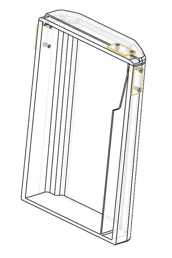 It should be visible here that there's a few design considerations, the side-section of the case (shown right) is its own compartment for hiding spare propellers and a screwdriver. To prevent the 'oh dang-it the props are jammed down a long slender encasement' i opted to make the top somewhat open. This allows you to reach down and grab things without them getting jumbled around inside. The M2 thermal inserts are small, but namely they are also thin. I did not want to end up with a hefty front and rear portion of the case just so thermal inserts had room to seat. I also did not want the aluminum / brass plates to be thick enough to catch on things when in a bag, as such i opted for fairly thin material. I think sanding / beveling the sides should mitigate that issue. Its also not clear if the compression will be enough to hold the Velcro strap in place, i may end up putting a small amount of silicone glue / epoxy to keep things from coming loose. |
|
First
cad model: a snap-on lid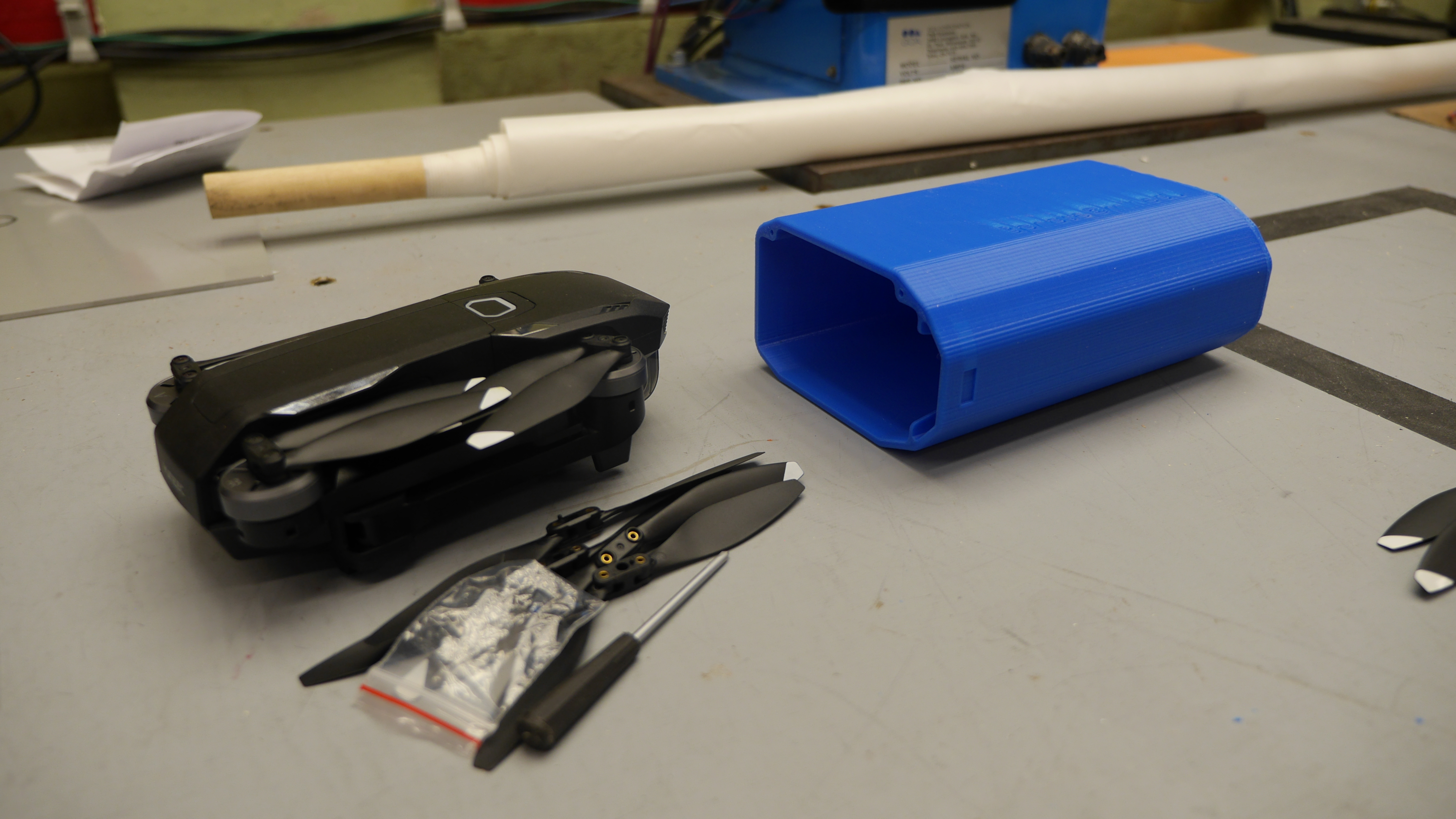 My first attempt relied on a snug-fitting lid with small detentes to be the retaining mechanism. This was admittedly an after-thought, as i was mostly after getting the drone-fittment right. Shown is the case and everything that fits inside. It actually all fits and its printable! This actually worked fairly well for a first pass, but I ended up having to tape on the lid with some gaffers tape so it wouldn't come un-done in the backpack / on a trip. |
|
Fitment:
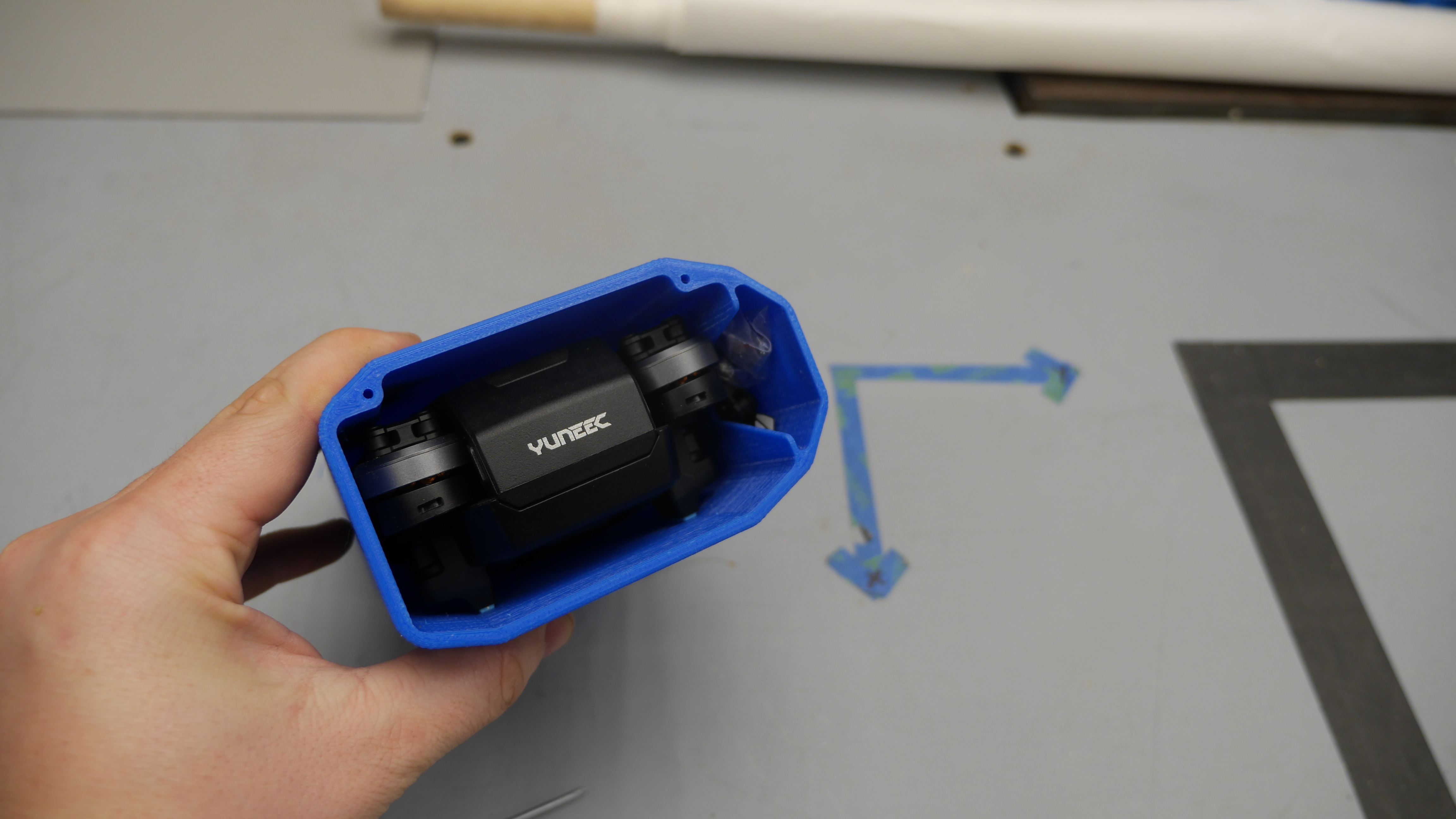 Isn't this this great? It fits remarkably well, slides in and out without too much of a close fit. The screwdriver + propeller side case is a bit tight, you can just fit 4 props and a screwdriver but its a stretch. Scoot-ing that area out a bit and adding in some features for a Velcro-able lid are the only main changes I'm after for the next version. |
|
Wait
what about cushioning? Let me introduce you to, socks. What is the shape hiding in that astronaut sock? Its a mantis drone. This was a long-sock that I lopped the foot part off of an hot glued shut. Yes it could have been sewed, but I was being impatient. I love that this drone fits in a sock. |
|
Prepare for a long print
Here is a time-lapse of the case 3d print, approximately 20 hours, printed out of blue Dremel brand PLA on a Type A Machines: Series 1 printer, yep this printer [link] its still up and running! The Type A machines printer was upgraded to have octoprint and this time-lapse was done via octolapse, using a c920 Logitech camera [link]. Interestingly, you end up disabling auto-focus and setting fixed lighting levels as a bunch of time-lapse snippets with auto focus / auto gain settings results in a chaotic mess of blinking lights. I've been meaning to make an external GPIO toggle for a DSLR but that is a project for another day. For a filament I used the dremel blue 1.75mm PLA. I've found that its surprisingly repeatable, and consistent. The color is identical between spools. |
|
Printing A lid
The new style lid is a quick print, and it lives on the velcro-strap with a small plate. Due to its geometry, it was printed on a raft with a bunch of support material. This ends up with a fairly smooth outer face, which was optimal as there would end up being less sanding to get the part complete. Like the case, shown above, three layers are used on any outer face, this gives a bit more material for sanding / surface prep. |
|
Sanding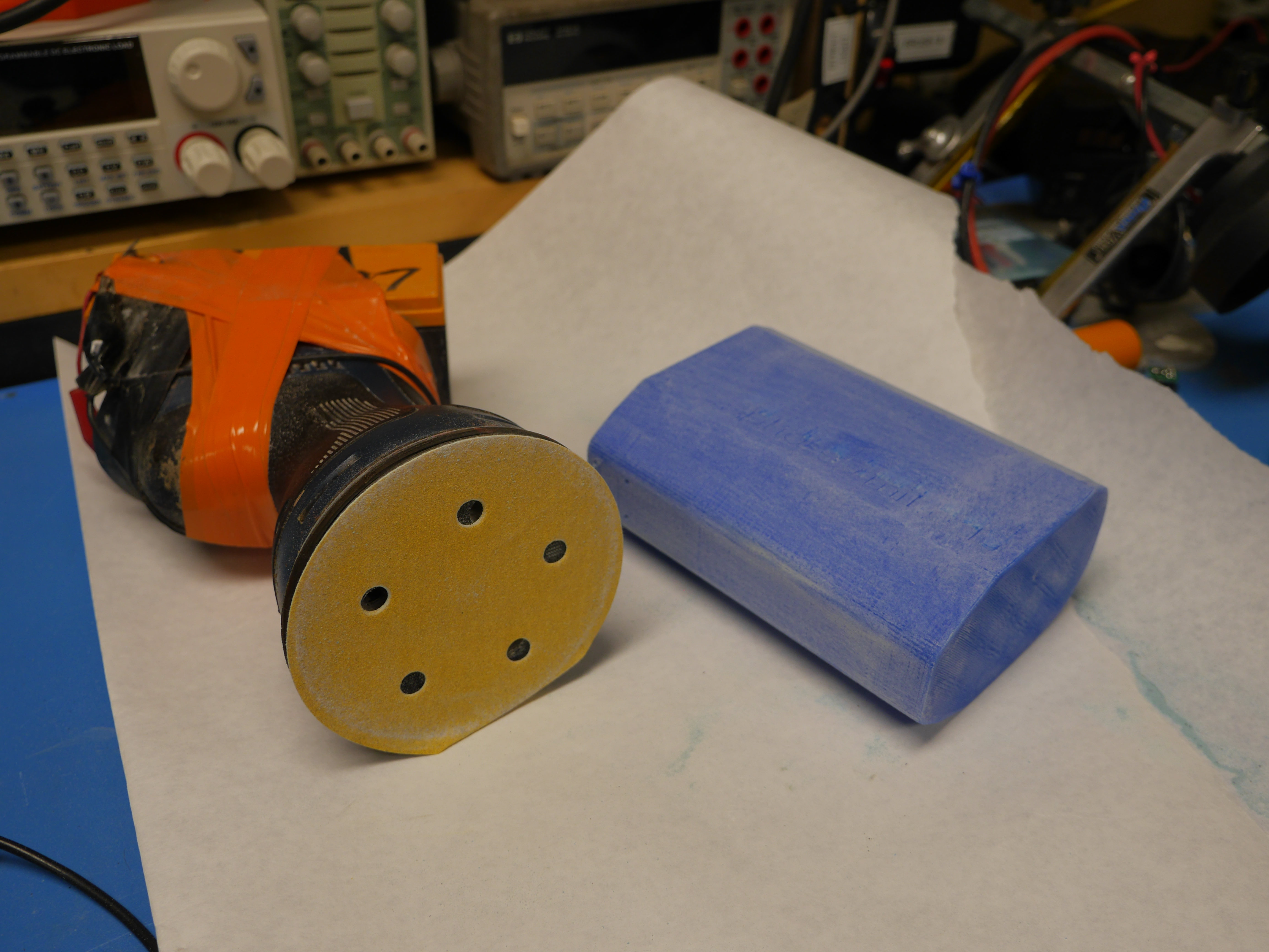 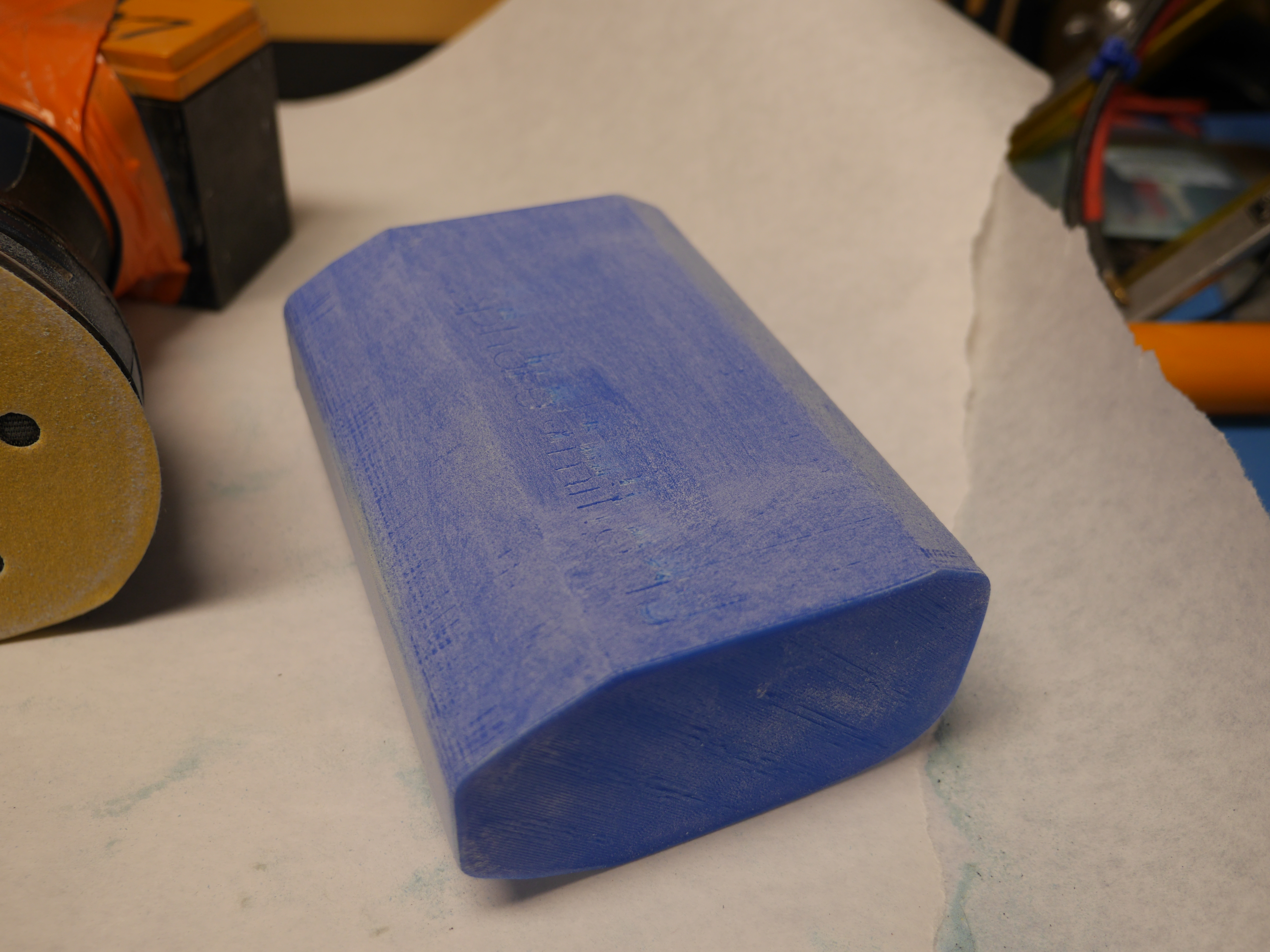 The sanding process is pretty straightforward, I use an older orbital sander (with a 12v lifepo4 battery attached to the top, in place of its old very very depleted Ni-Cd battery). One of the keys to getting the surface to be reasonable is to keep track of temperature and have a few sanding disks on hand. Unsurprisingly, you actually need to do the whole 120 -> 220 -> 600 -> 800 grit sanding process to get a reasonable finish. I was tempted to use a small torch to 'melt' the surface flat, but I'm warning you ahead of time, it does not work well, the surface sinks-in and you end up just seeing the support material. One final note, plastic is not thermally conductive, so if you hover over an area for any extended period of time you end up with thermal buildup. As a result the plastic doesn't ablate off, it gets gummy and the surface finish suffers as a result. |
|
Thermal
inserts and a lid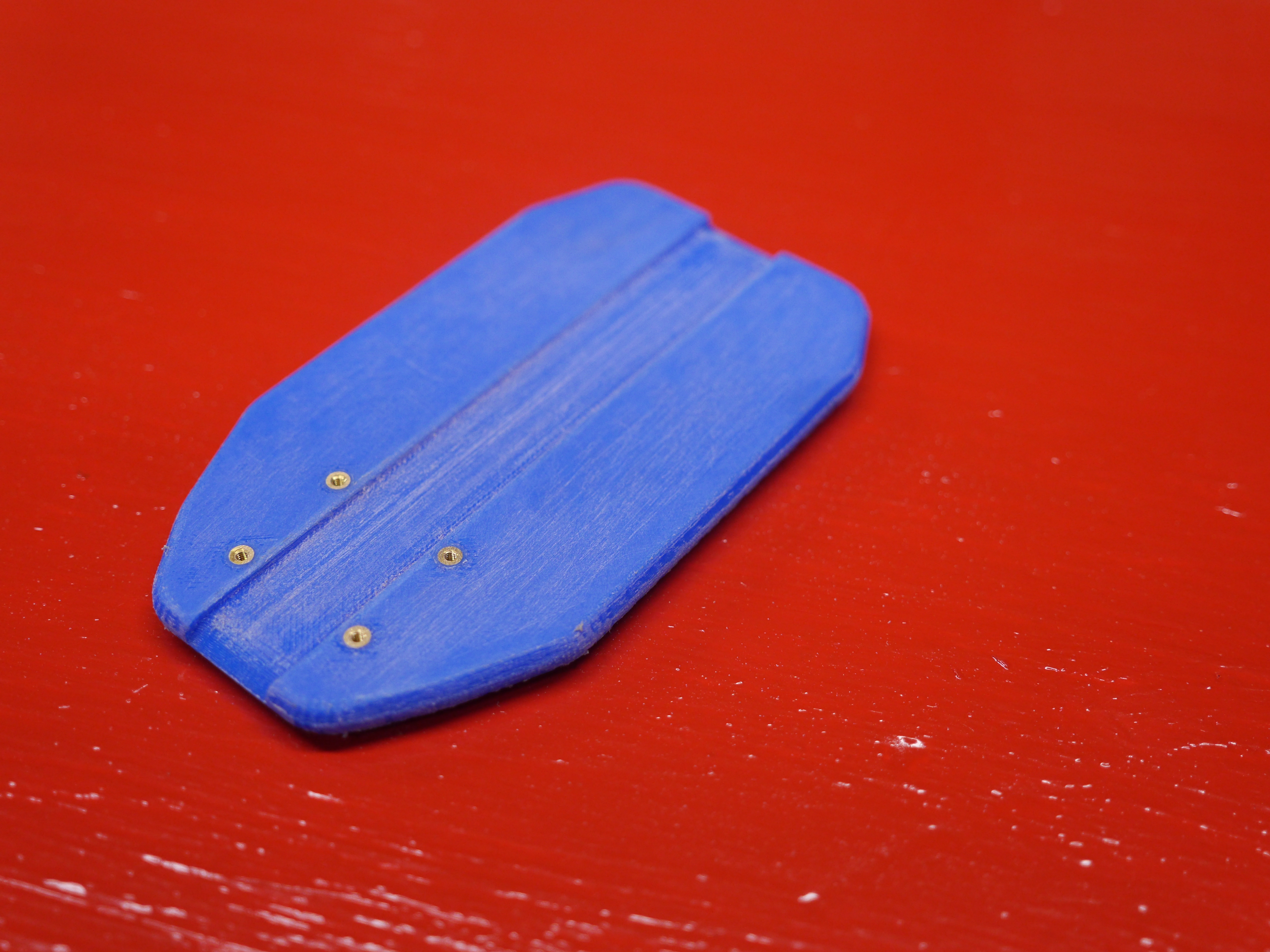 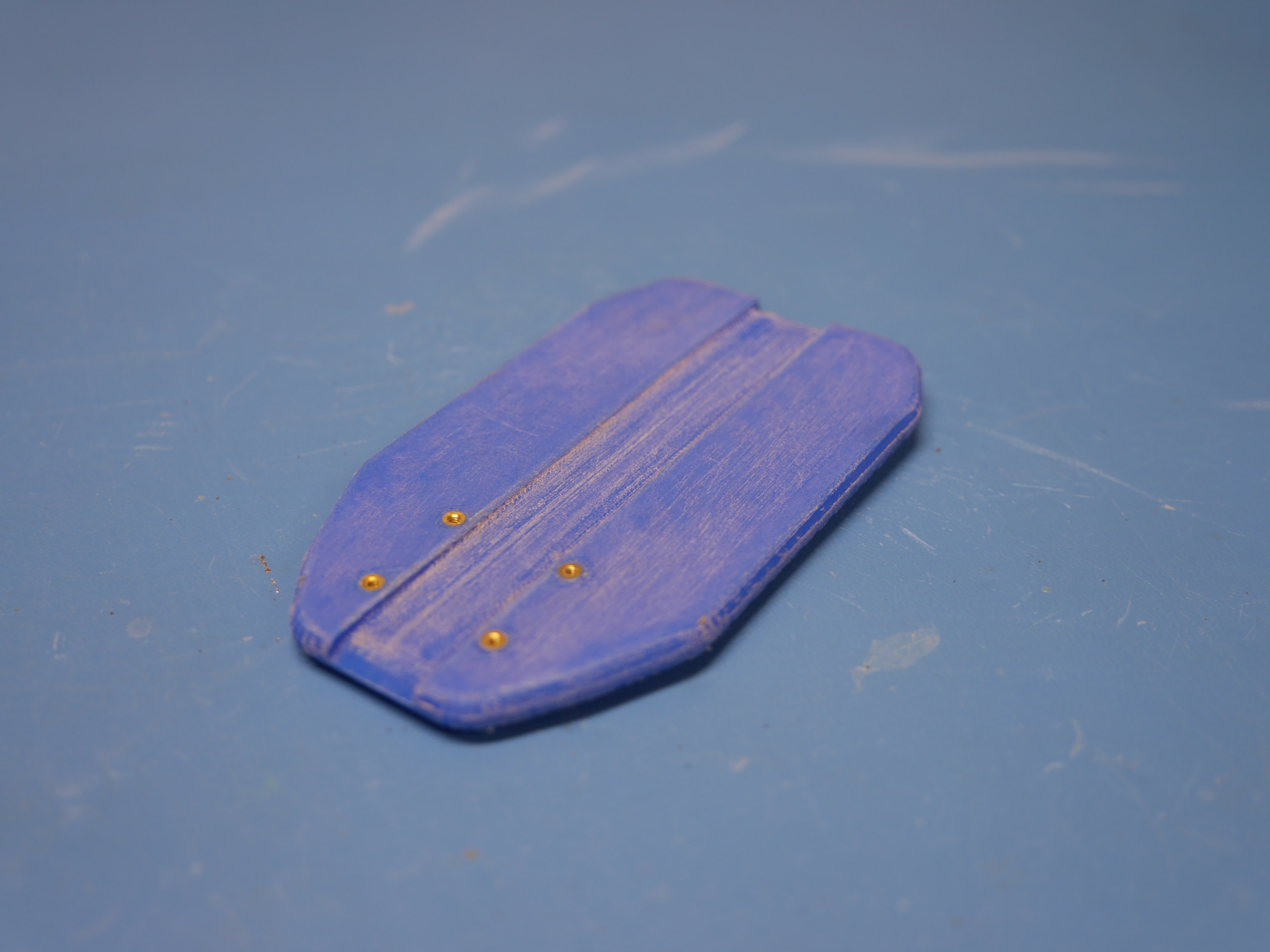 Applying thermal inserts is always kind of a treat, brass inserts just look so good. I got too excited and applied the thermal inserts before I started sanding the part and they really meld into being part of the lid. Note these were applied by hand using the 'I don't have the correct tool for this approach'. My method is pretty simple:
|
|
Quick thermal insert process
If you don't have a thermal insert soldering iron, or the specific tip for your thread, you can just opt for an easier route: using a long screw. Off camera I placed the thermal insert on the end of a long screw, with the screw threaded all the way through the insert. I heated the insert while holding the screw with a pair of pliers, and once it was hot enough, you just press it in place. Note that the inserts do displace material as they go in, so expect a small lip at the top of the part, this comes of easily with flush-cutters. I like inserting the thermal inserts before sanding, as you can merge the brass right up to the printed surface. |
|
Tips
and Tricks on thermal inserts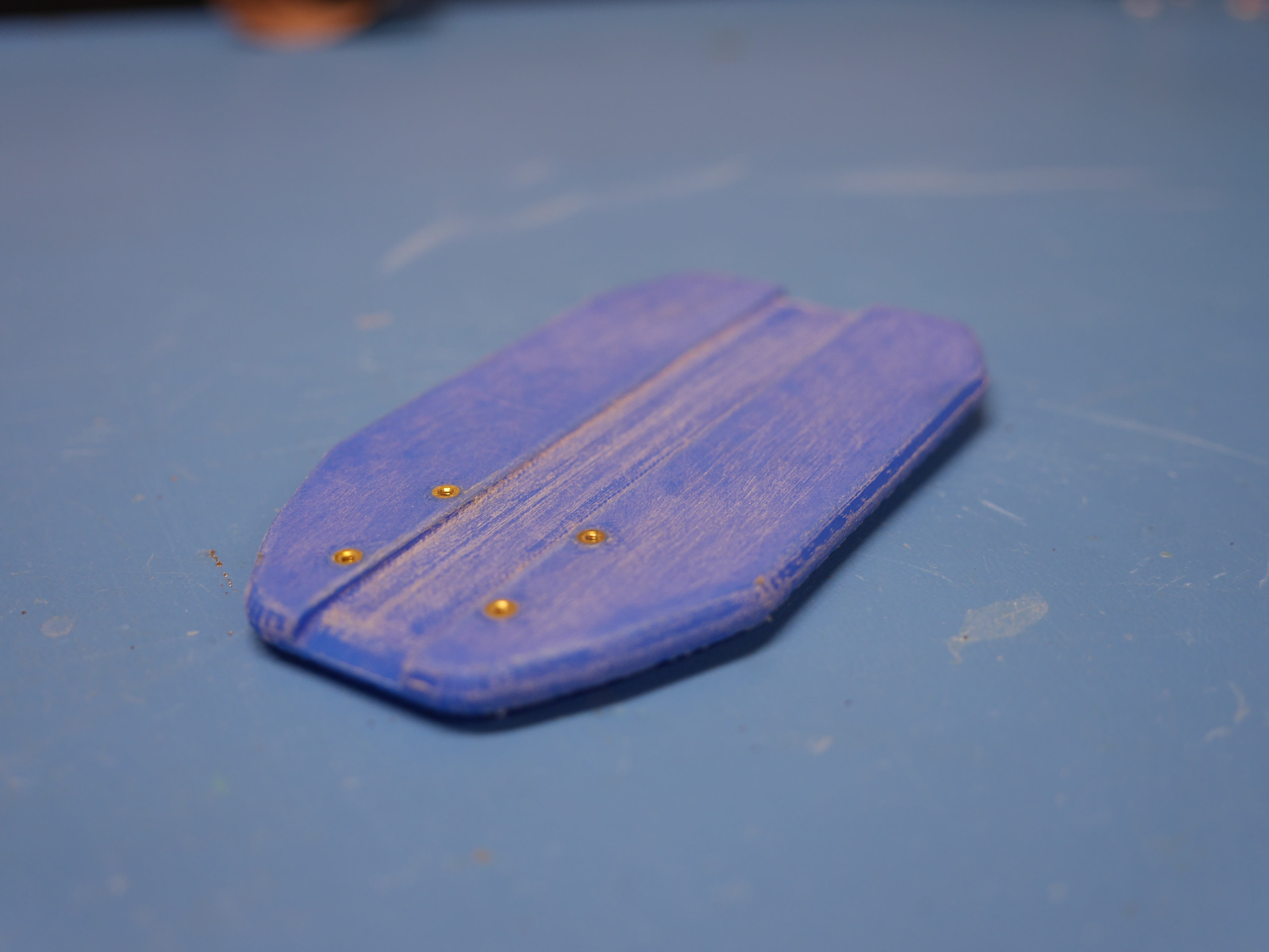 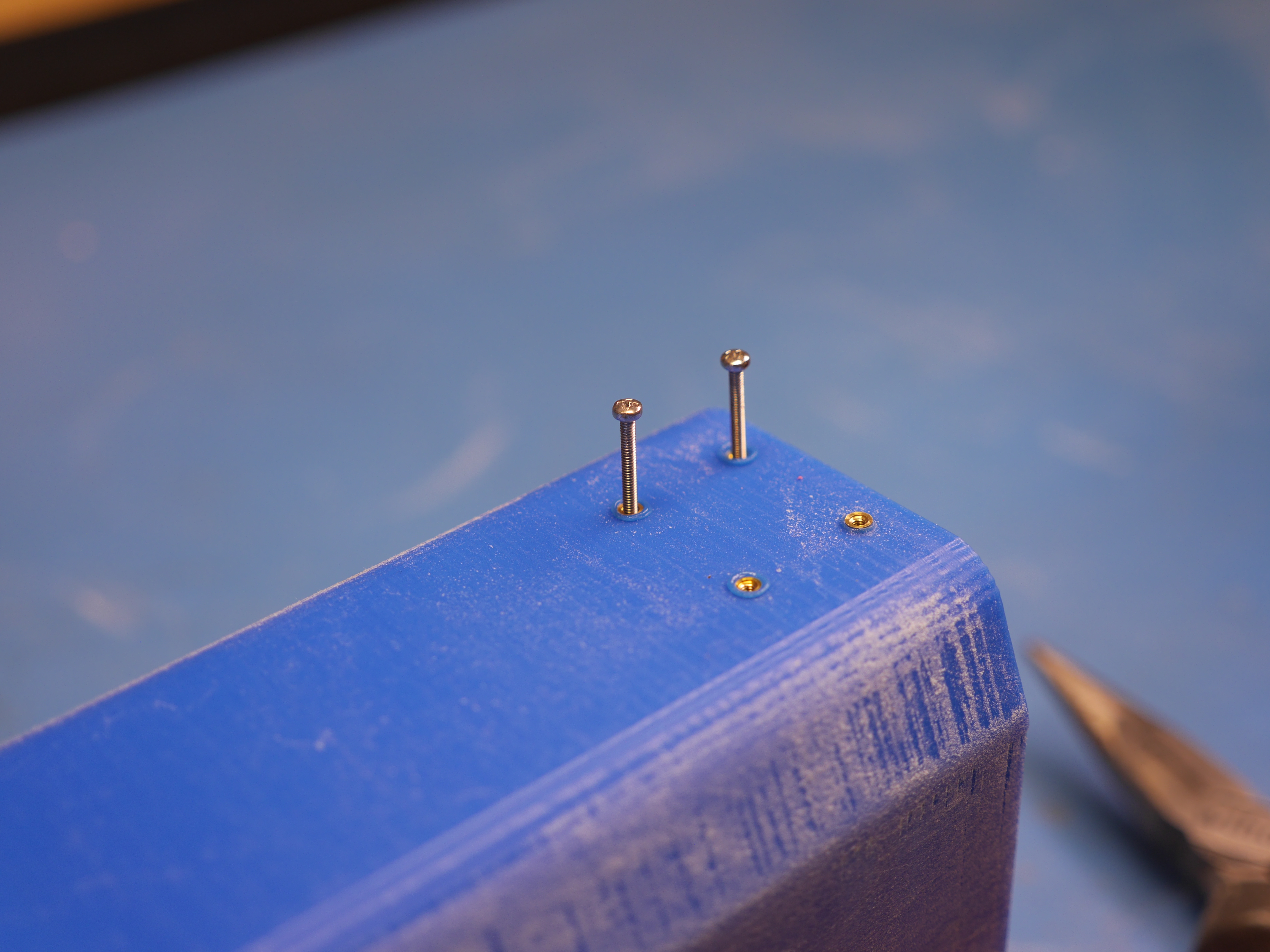
|
|
A bunch of sanding
Because this part has a lot of flat surfaces, you can get away with a normal ~6" random orbital sander. This print didn't look bad but i wanted the 'this is a smooth nice thing' look, and man did this require a lot of sanding. My printer is a modified Type A Machines Series 1 [link], these parts were printed at 0.15mm layer spacing with a 0.4mm nozzle using Dremel brand blue filament. I opted for 3 outer layers so that there was plenty of material to sand down. The sanding process starts with 120grit sanding disk with the goal of getting the surface down to a flat even surface, then swap to 220 and 400 grit. The amount of dust is somewhat surprising, so wear a face mask. Note that the surface becomes white-ish, that is OK, when we complete the final coat it all looks normal again, but way way smoother. |
|
Leveling
off inserts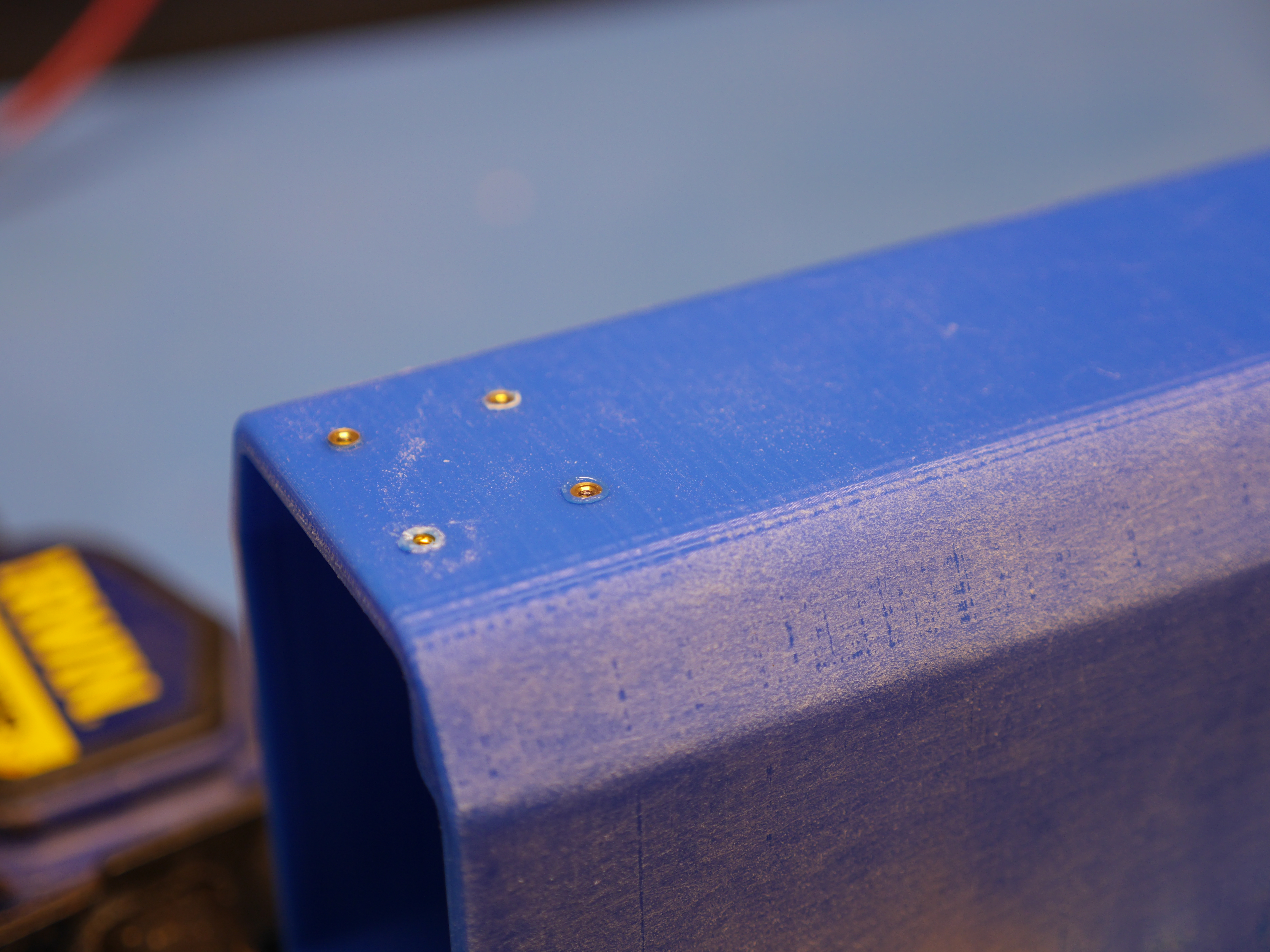 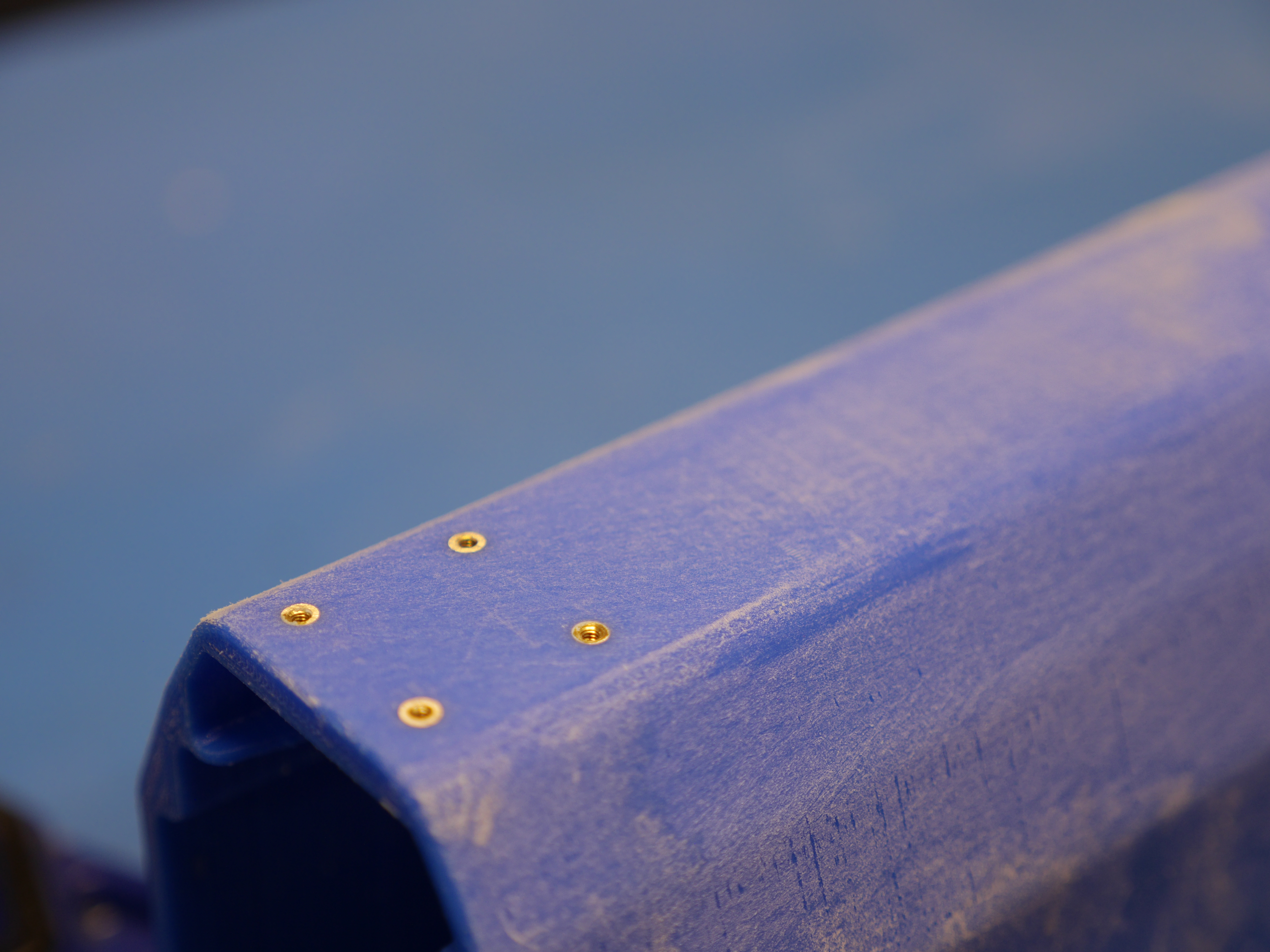 Mentioned above, its somewhat hard to get the height right on small inserts. As these M2 size, its somewhat even more fiddly. Fortunately brass is really soft, so sanding its relatively easy, note you can see three of the inserts are slightly raised while one is slightly sunken-in. You can use spray water to keep down dust, the only downside is the sandpaper may degrade quicker due to the paper loosing rigidity. I've also found that wet sanding does get the inserts full of goop-y plastic dust, but it does come out rather quickly with compressed air. I started with 120 grit and moved up to 400 grit. |
|
Finishing
up the sanding process 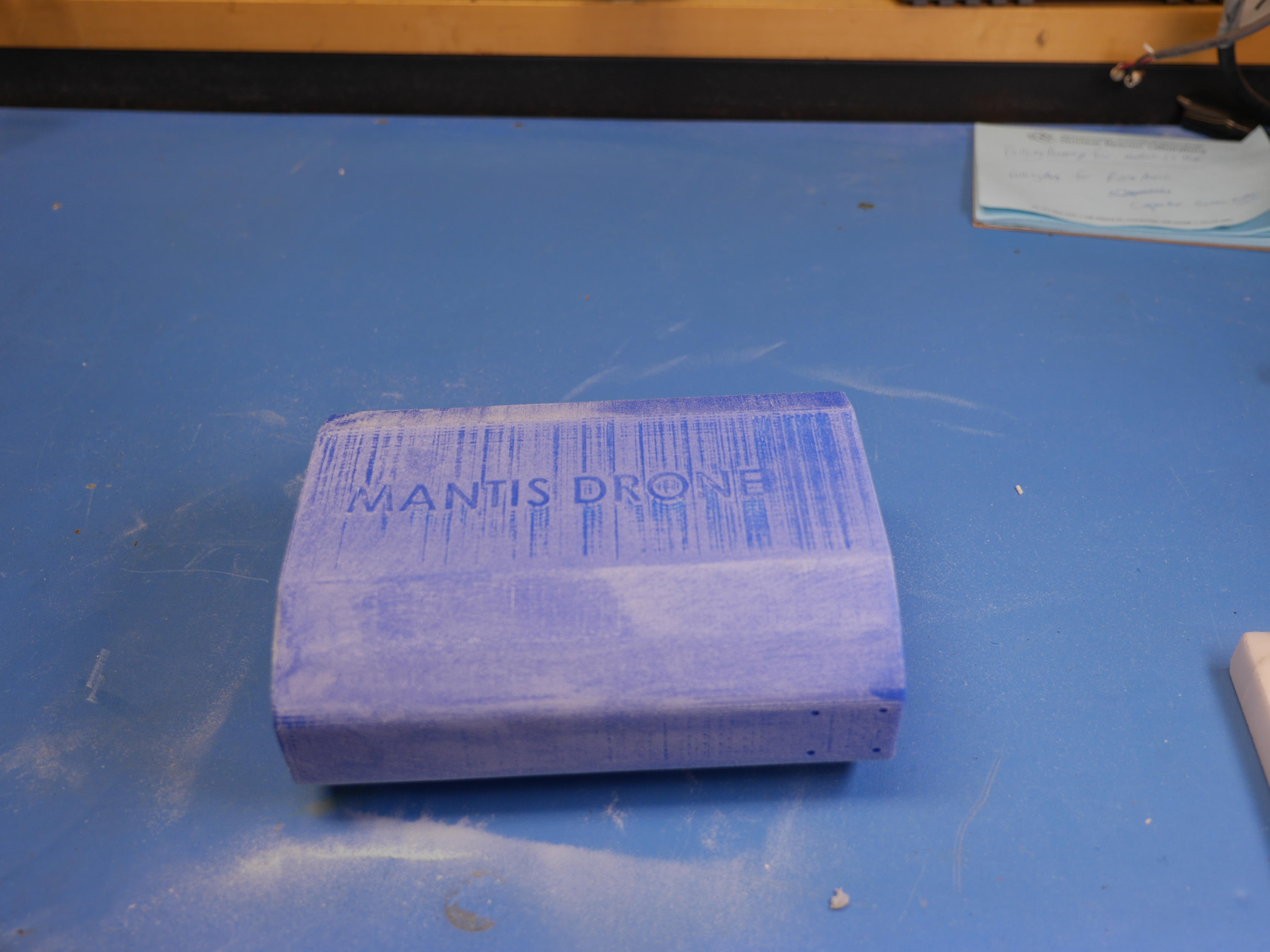 Switching between 120 -> 220 ->
400 grit we end up with a fairly reasonable finish, but
the part looks powdery white, before painting it was
fairly important to dust everything off with compressed
air. Switching between 120 -> 220 ->
400 grit we end up with a fairly reasonable finish, but
the part looks powdery white, before painting it was
fairly important to dust everything off with compressed
air. |
|
Coating
with acrylic paint
The camera was a bit capped height-wise but all the thermal insert screws were 'covered' by having small screws threaded in, this prevents the threads from getting covered and need to be re-tapped or cleaned out. I was having some issues with this particular 'satin' acrylic spray, it seems the nozzle was acting up, as a result there was some 'spittle'. I was able to get it to clear up by spraying some compressed air. The part is sitting on a small dc-motor rotating table, with three small printed 'triangle widgets' holding it up. These provide a very small contact area to help the part not stick to the thing it's sitting on. After the first coat I re-sanded with 800 grit sandpaper and did a subsequent coat. As it turns out the inset lettering didn't quite work out as I expected, so I opted to not paint fill the lettering. |
|
Making
the brass clamp plates: Drilling
To make the small brass plates, I opted for a simple print 1:1 on paper stuck to the brass sheet stock and cut / drill based on the paper markings. Note it was easier to drill first as you could hold the whole sheet for leverage, and then cut the outsides. The paper is just double-sided-taped to the brass sheet. Initially I was going for 0.090" thick brass sheet, but it was a bit too flimsy, so i ended up using 0.12" sheet stock. The drillbit is slightly oversized for M2.5. These plates are fairly small, it would have been a bit better to center-punch at the crosshairs of each part. |
|
Making
the brass clamp plates: Band sawing
The order of operations for this is fairly important, I opted for band sawing around all the parts so that only the rectangles would be removed, without having to hold them individually. It was also important (but a bit hard to see) that the cuts were a bit wide of the mark, so they could be belt-sanded to the correct size. Given how close the screws were to the edge of the corners this also had the benefit of not getting too close and having to re-do the parts. |
|
Making
the brass clamp plates: belt-sanding
The paper side was used as a guide and the parts were sanded to match the perimeter drawing. Note this belt-sander is lacking a base-guard that extends to the belt so it was easier to do floating. Watching this just realized i should make an aluminum floating base that just has magnets and can be forced closer to the belt to allow closer sanding operations. |
|
Adding
in the brass clamp plates
I was surprised how well this fit. I had purchased some flush-mount screws but as they are M2.5 and very small, they evaporated. I'm impressed by how well this fit, i may put a small amount of silicone or RTV to ensure that the bands that are attached to the case don't come out but otherwise this is excellent. |
|
| CAD
Files for the drone hard-case Solidworks [2017] pack and go cad files [zip] STL file for case without an email address embossed on the back [link] STL file for the lid [link] Thingiverse [link] |
| A hard-case for the
remote |
|
I opted for an open-ish bottom, mostly so I could push the remote out if it gets stuck, and an open top with just a Velcro strap going across. The Velcro strap (not shown) is clamped in place on either side with a plate and some M2 screws and synches over the remote. While this is somewhat thin-walled, the remote is fairly structural and folded up, so I'm not concerned about it surviving some bouncing around. I may opt for a similar lid if its possible to get too much dirt and grime in the case but for the first version cap-less should be fine. |
|
 Somewhat visible on this cad render
is a space for the USB-A to USB-C cable used on the
remote. The first variant of the assembly was a bit too
shallow so the cable was a tight fit. In this version I
opted for a larger cavity. Otherwise the base of the model
is filleted, as the controller itself is fairly curvy.
This also provides some extra structure on the end of the
assembly. Somewhat visible on this cad render
is a space for the USB-A to USB-C cable used on the
remote. The first variant of the assembly was a bit too
shallow so the cable was a tight fit. In this version I
opted for a larger cavity. Otherwise the base of the model
is filleted, as the controller itself is fairly curvy.
This also provides some extra structure on the end of the
assembly. |
|
Here's a time lapse of the controller case print. The controller itself is awkward sized, everything is compact and folds in, except the hand-sticks. I opted to cad around the controller and have a slot for the 'sticks' to slide into. The only other required part of the case is a small area for hiding the short USB-C cable to interface to the phone. There's not really a need for a cover (or so I guess) but I'm opting for a similar design as the hard case for the drone, it did come out pretty swanky and adding the lid is fairly quick. |
|
Some
sanding upgrades for small areas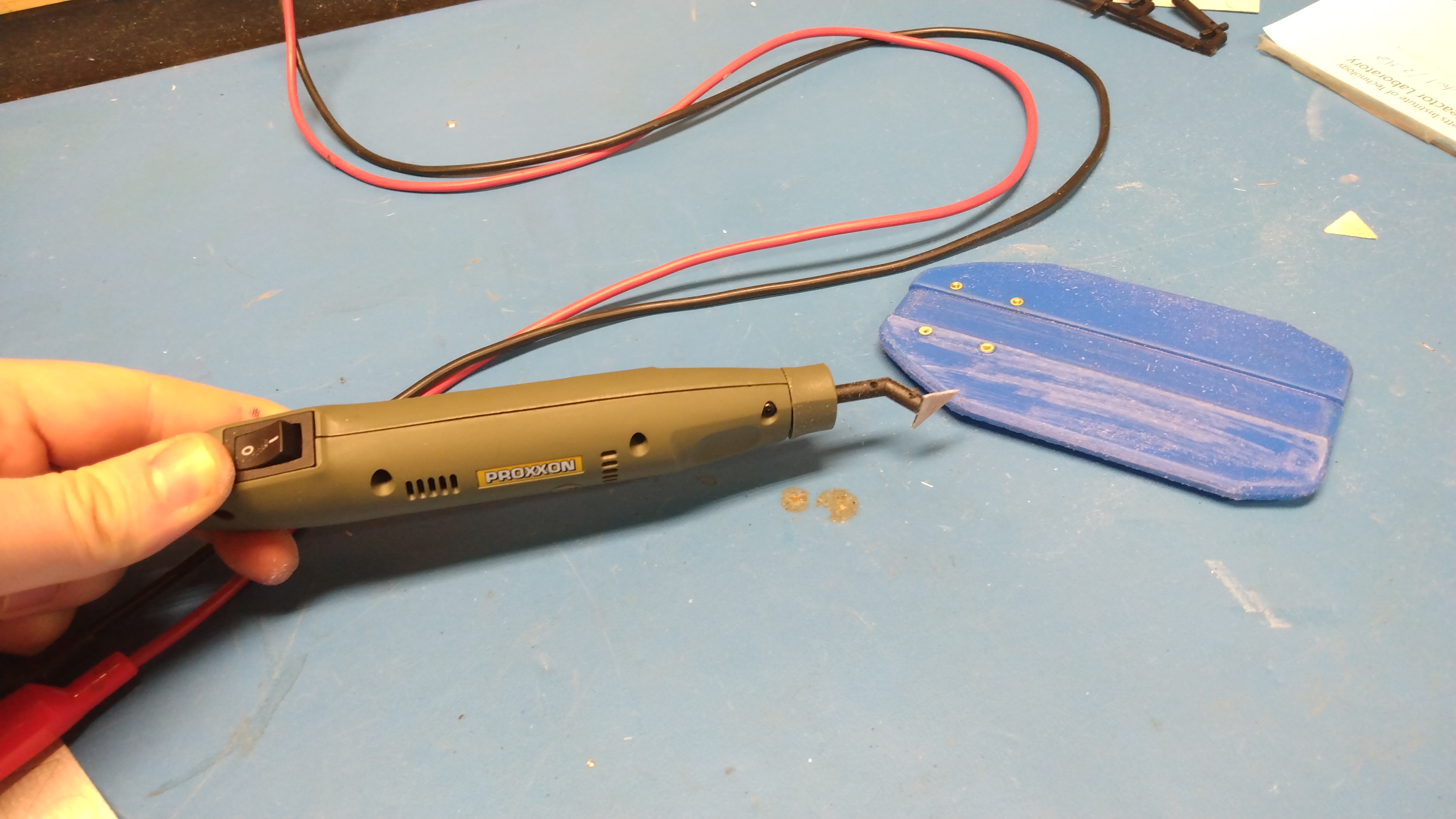 I purchased a Proxxon tiny-vibrating-sander contraption used on eBay. This is pretty useful for cleaning small parts, it does use a goofy connector, but nominally its just a 12v motor inside, so using a power supply worked just fine. The sanding surface is adhesive-sticker-ed on, which works OK for the most part, sometimes it just comes off which is not wonderful. The Proxxon 28594 Pen Sander is available on amazon [link] for around 40$ as of 2021, as long as you know you can just lop the connector off and connect to a power supply, you're all set. I found that you can purchase pre-cutout sanding pads on eBay, and for the price its totally reasonable. If you already have adhesive backed sandpaper that can work too. |
|
| CAD
Files for the controller case Solidworks [2017] pack and go cad files [zip] STL file for controller case without an email address embossed on the back [link] Thingiverse [link] |
|
| Looking
at the multi battery charger |
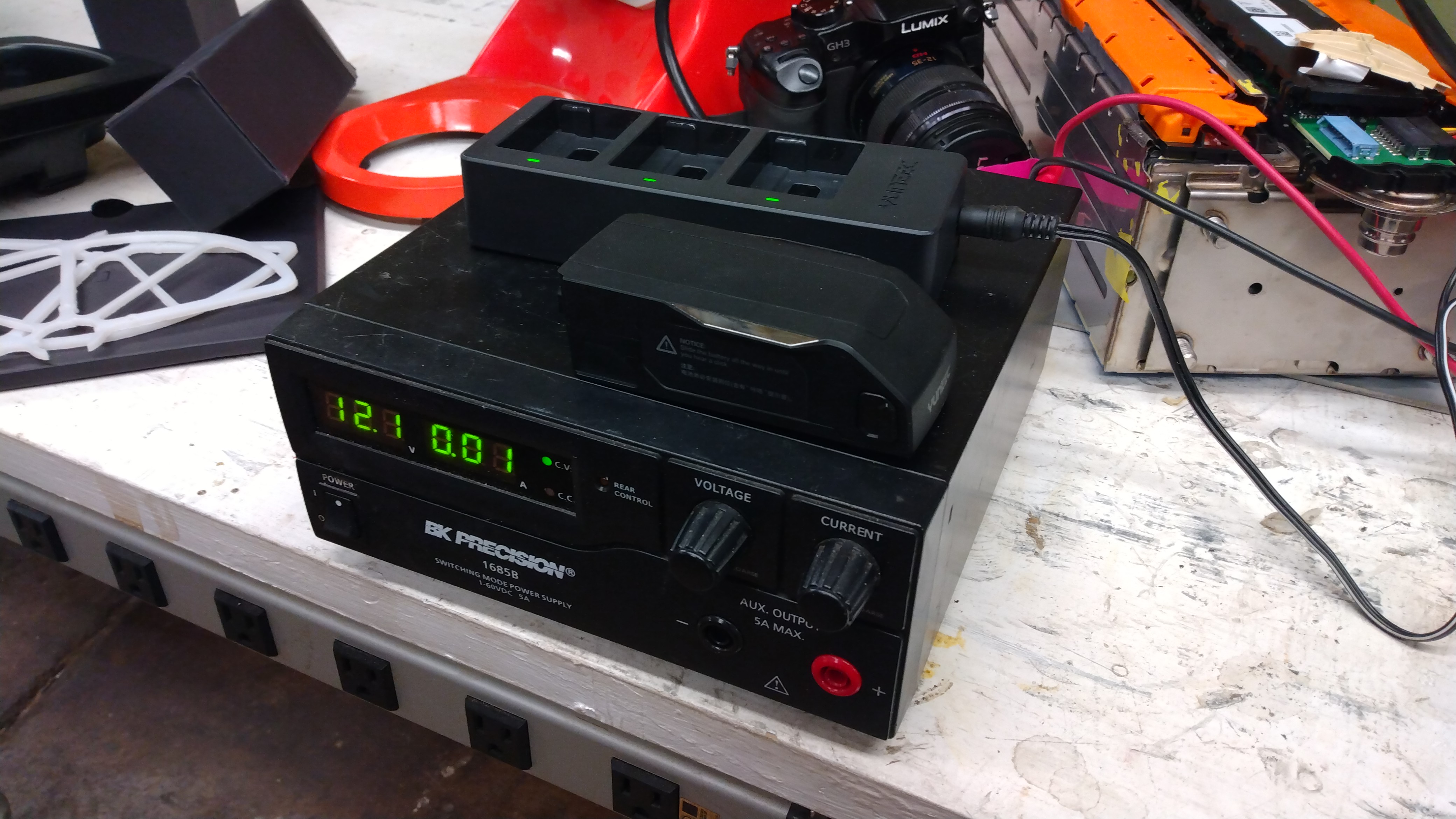 So there's this multi-battery charger
that ships with the drone, it fits 3X of the stock
batteries. Really interestingly it only wakes up at 12.5v,
not 12v. The power supply is labeled 12v but lets do some
digging. So there's this multi-battery charger
that ships with the drone, it fits 3X of the stock
batteries. Really interestingly it only wakes up at 12.5v,
not 12v. The power supply is labeled 12v but lets do some
digging. |
Interesting
notes from the back of the charger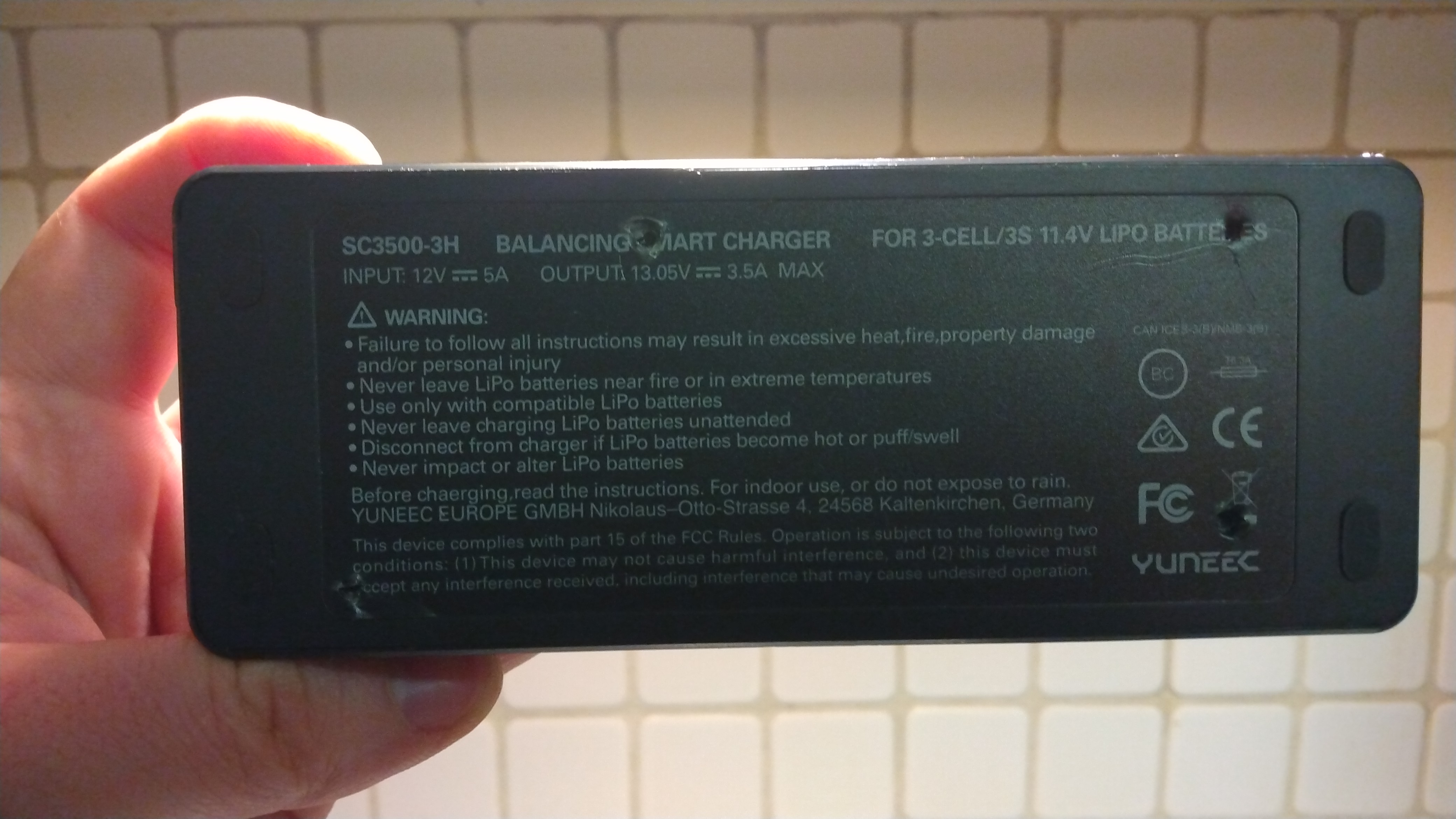 Really curious, we learn from the back of the box that there's an internal boost converter taking in the 12v input, boosting to 13.05v and likely doing CC-CV charging with some basic cell balancing. I really like that this is a '12v' block as it opens up some interesting doors, it suddenly could be plugged into vehicle power via a cigarette lighter adapter, may be chargeable over USB-C in USB-C 12v mode or just |
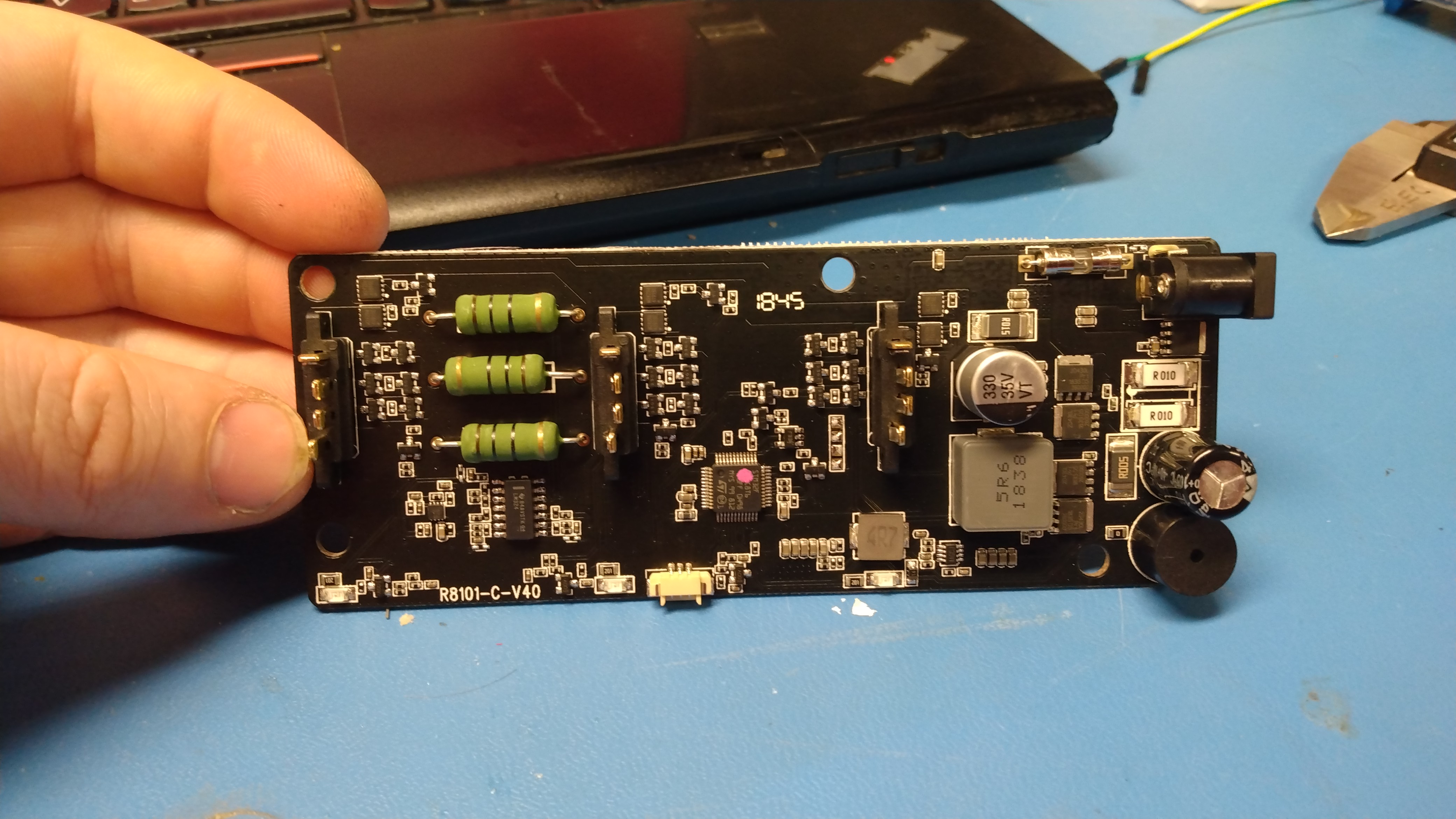 The stock charger PCB The stock charger PCBLooking at the board the design is interesting. Lets start from the basics, the drone battery is a 3S lipo, or 4.2 x 3 ~12.6v. First off this thing uses some real curious battery connectors, I have not been able to find them unfortunately, which is annoying. From the looks of it, external 12v comes in, passes thru a fuse, hits a big boost converter and then hits each pack thru a bleeder resistor to each pack + (I think). There's a curious lil connector down below which may be worth probing to see if it speaks serial. Otherwise the micro measures each cell voltage thru a resistor divider, which is OK for low series cell packs but ends up with a parasitic draw if the battery is left plugged in for a while. It appears only one battery group is charged at a time but I have not verified that yet. |
| Mantis Drone Batteries,
a deep dive |
| The
stock battery images of the stock battery |
 This is the mating connector for the
batteries. I was only able to find a random vendor even
mentioning this connector [link]
it has a very descriptive part number [U0009]. I tried
contacting them but I never received a response. I really
want to purchase mating pairs of these and both make some
custom batteries (3x 18650 Samsung 30Q's) and a custom
USB-c PD 3s charger, but they don't seem to be
purchase-able. I may end up having to make one. This is the mating connector for the
batteries. I was only able to find a random vendor even
mentioning this connector [link]
it has a very descriptive part number [U0009]. I tried
contacting them but I never received a response. I really
want to purchase mating pairs of these and both make some
custom batteries (3x 18650 Samsung 30Q's) and a custom
USB-c PD 3s charger, but they don't seem to be
purchase-able. I may end up having to make one. 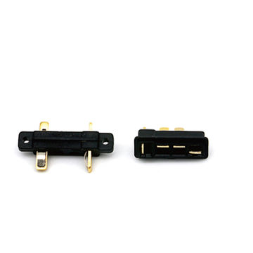 |
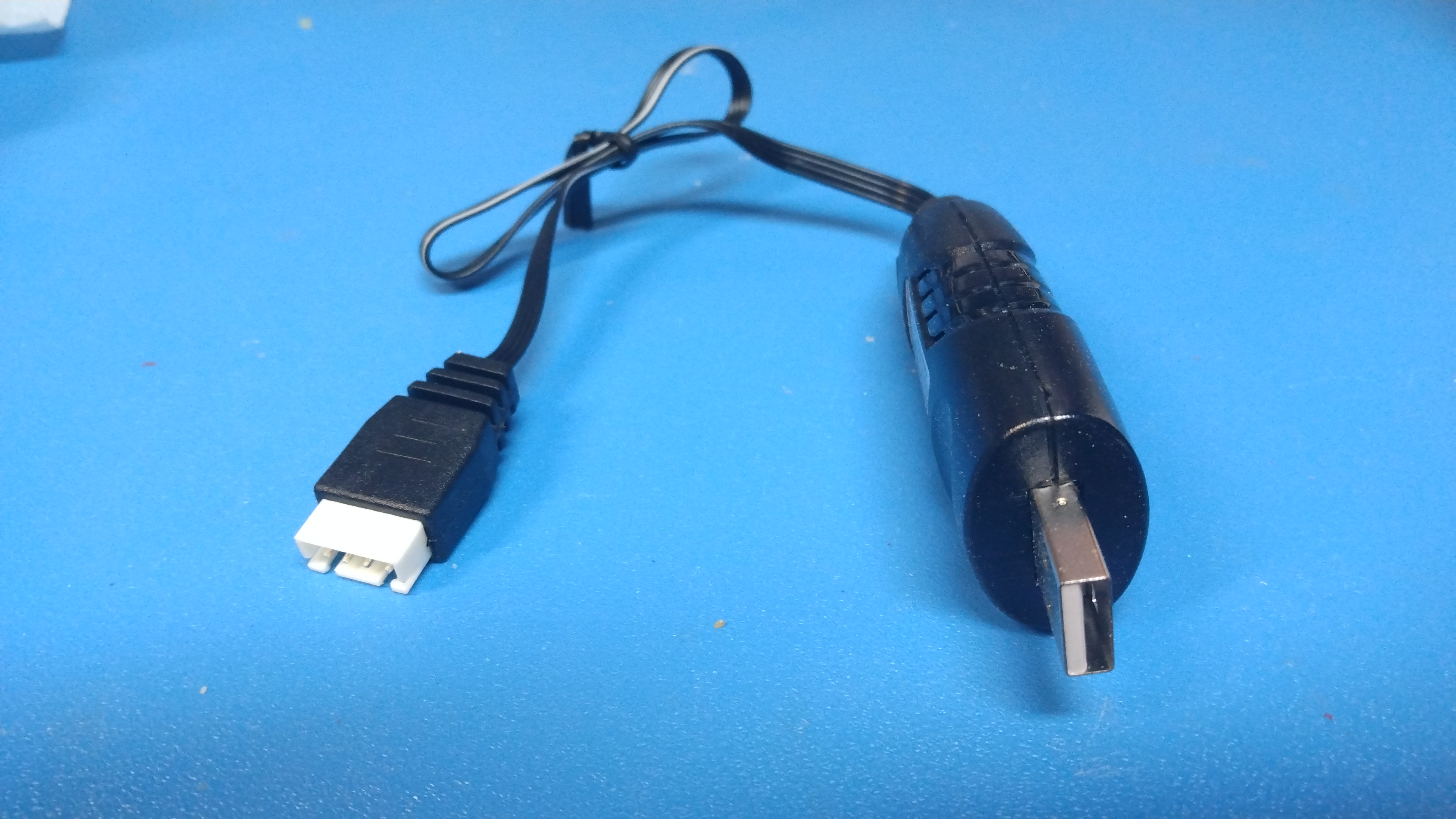  I bought some gadgets I bought some gadgetsThere's an interesting adapter available, its basically a 3S LiPo connector adapter, which is honestly great. This adapter really lets you do some quantitative testing on the state of health of the battery, run a capacity test on your home hobby charger, etc It does adapt the bizarre battery connector to something useful. I also found this somewhat strange USB -> 3s LiPo charger. Combined together it technically makes a USB -> mantis drone battery charger. Unfortunately its ~5W, so ~3+ hour charge time. What the heck is this USB-LiPo thing you ask? Good question, lets take it apart. The charger adapter is available here: [link] but also appears on amazon and Walmart surprisingly. |
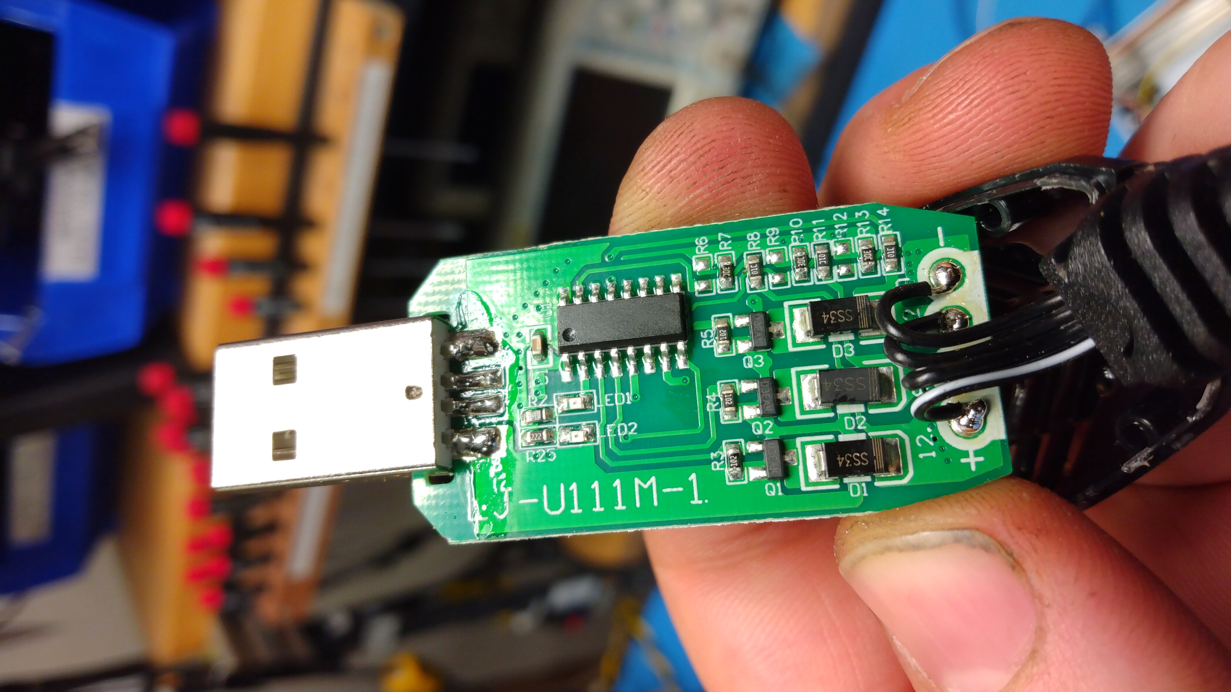 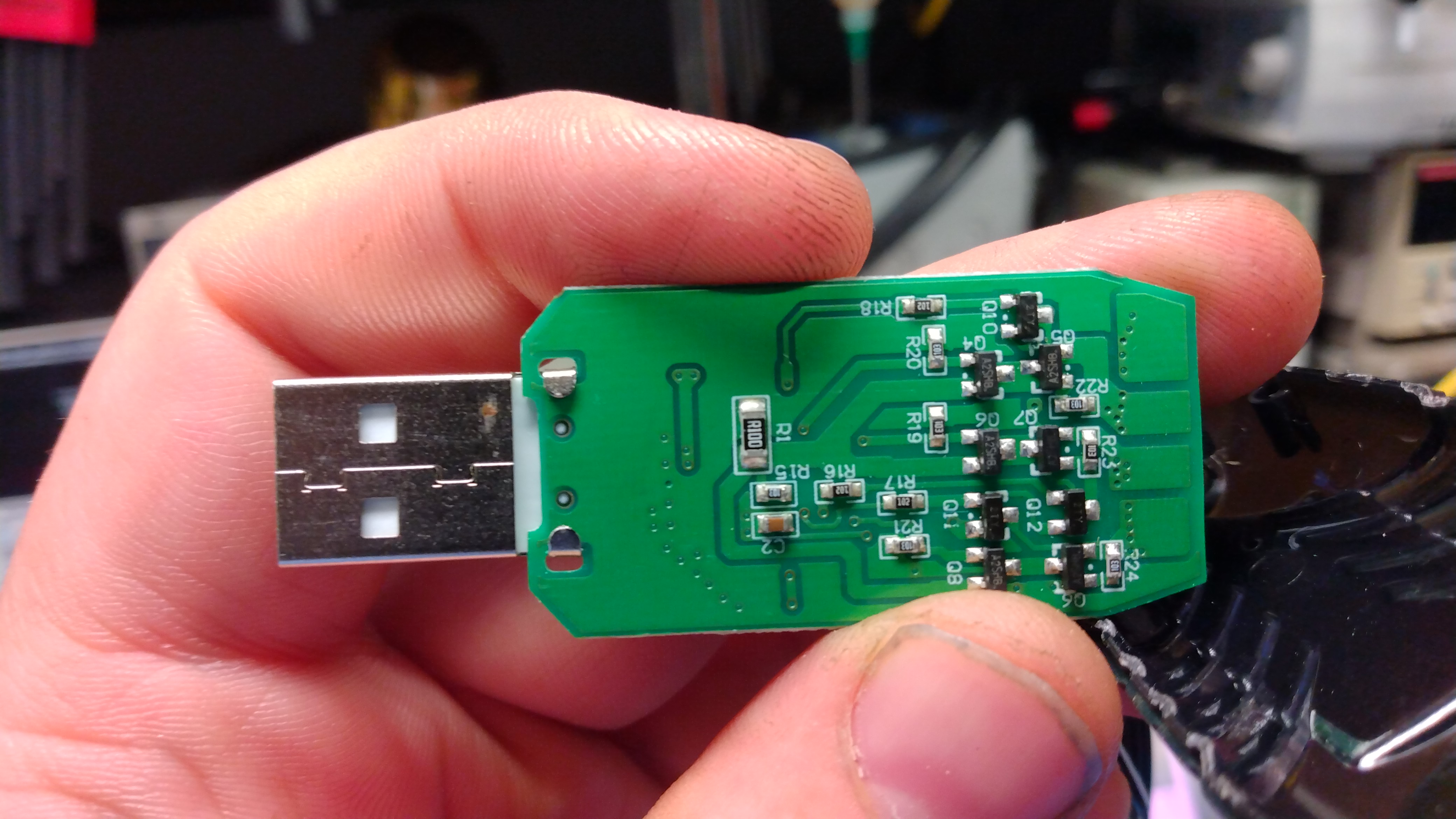 Insides of a
USB-3S LiPo Charger Insides of a
USB-3S LiPo ChargerOk that's illegal, I really expected a boost converter and some logic. This is not that, its actually connecting a linear current source to a single cell at a time, and cycles through cells. So cell 1 gets 1A for 5 seconds, then it cycles to cell 2, then cell 3. Unfortunately the control IC is sanded off. Really weird, and a really interesting way to implement this. Unfortunately its fairly slow, and a 3+ hour charge is a bit cumbersome. |
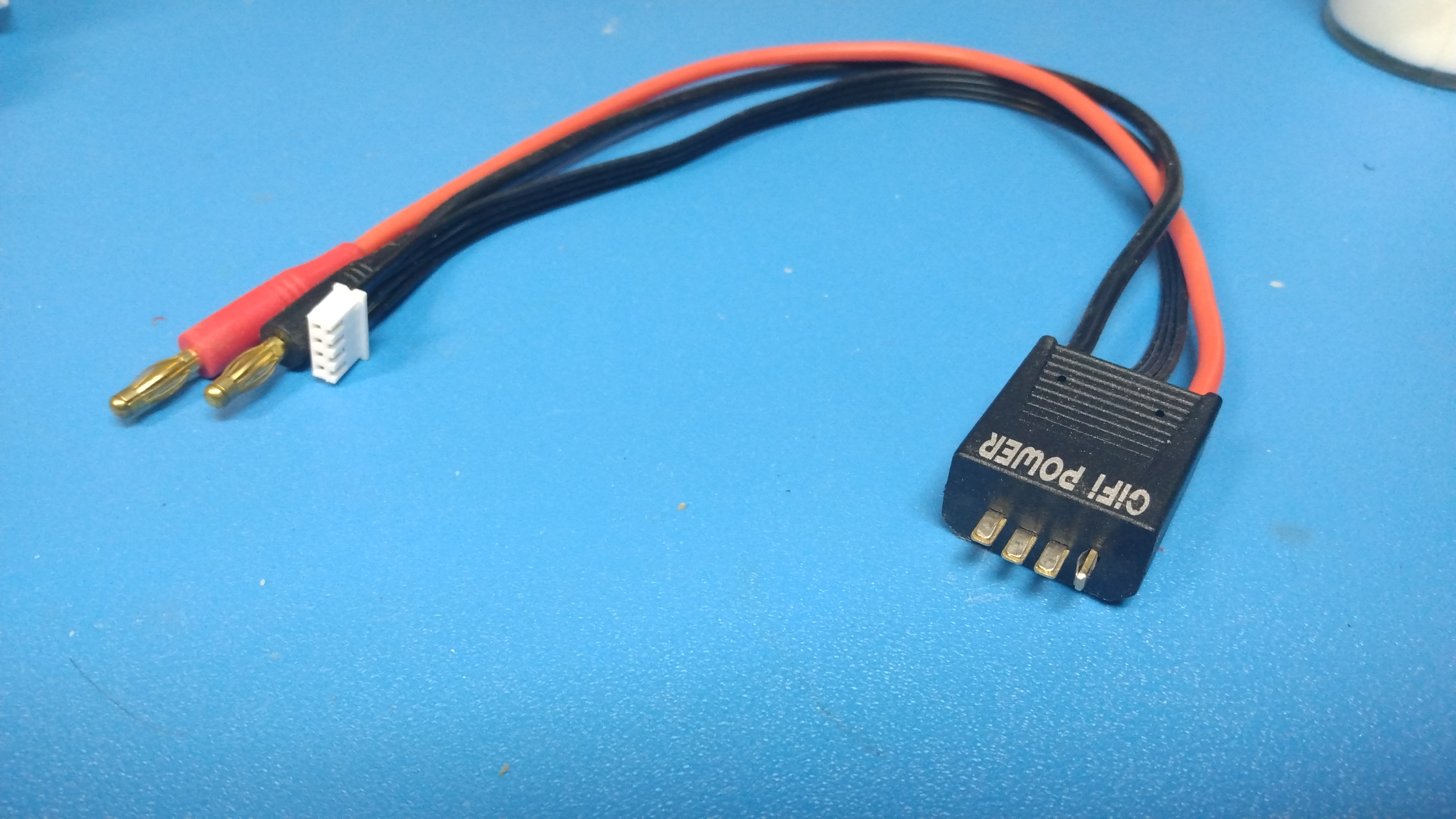
Capacity
Testing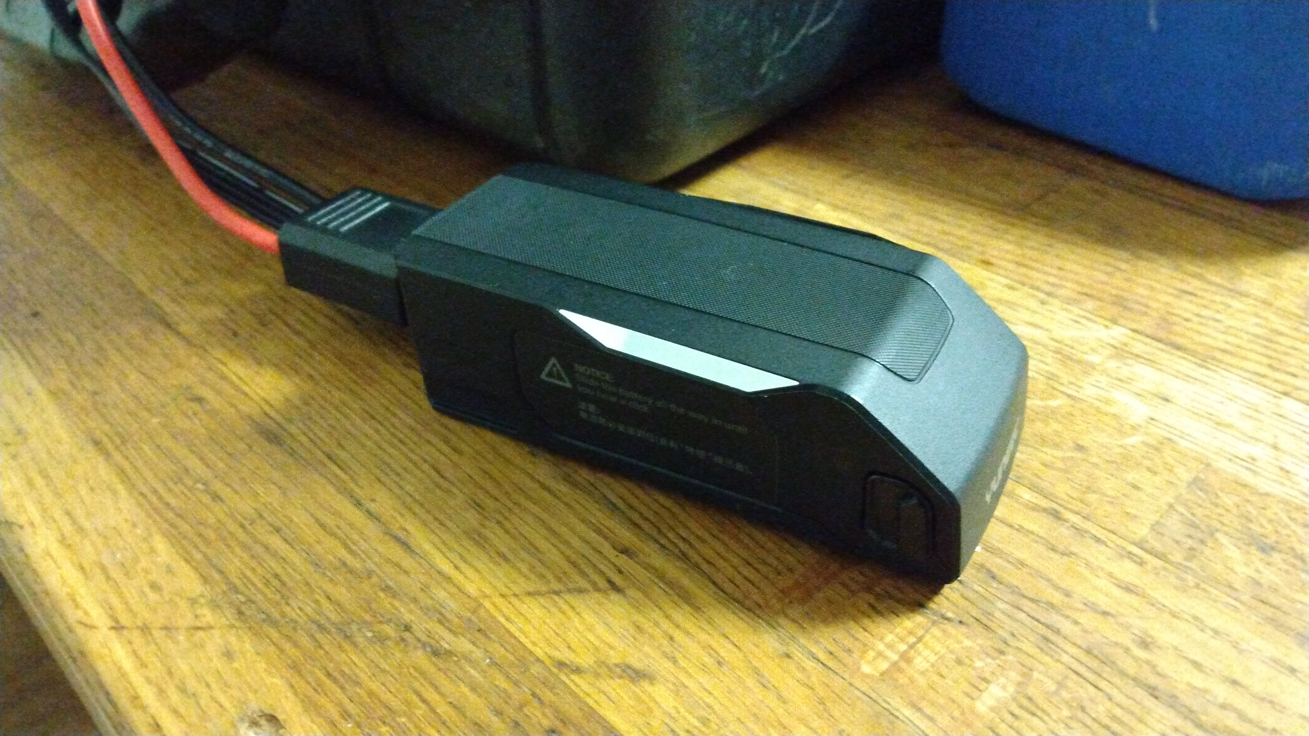 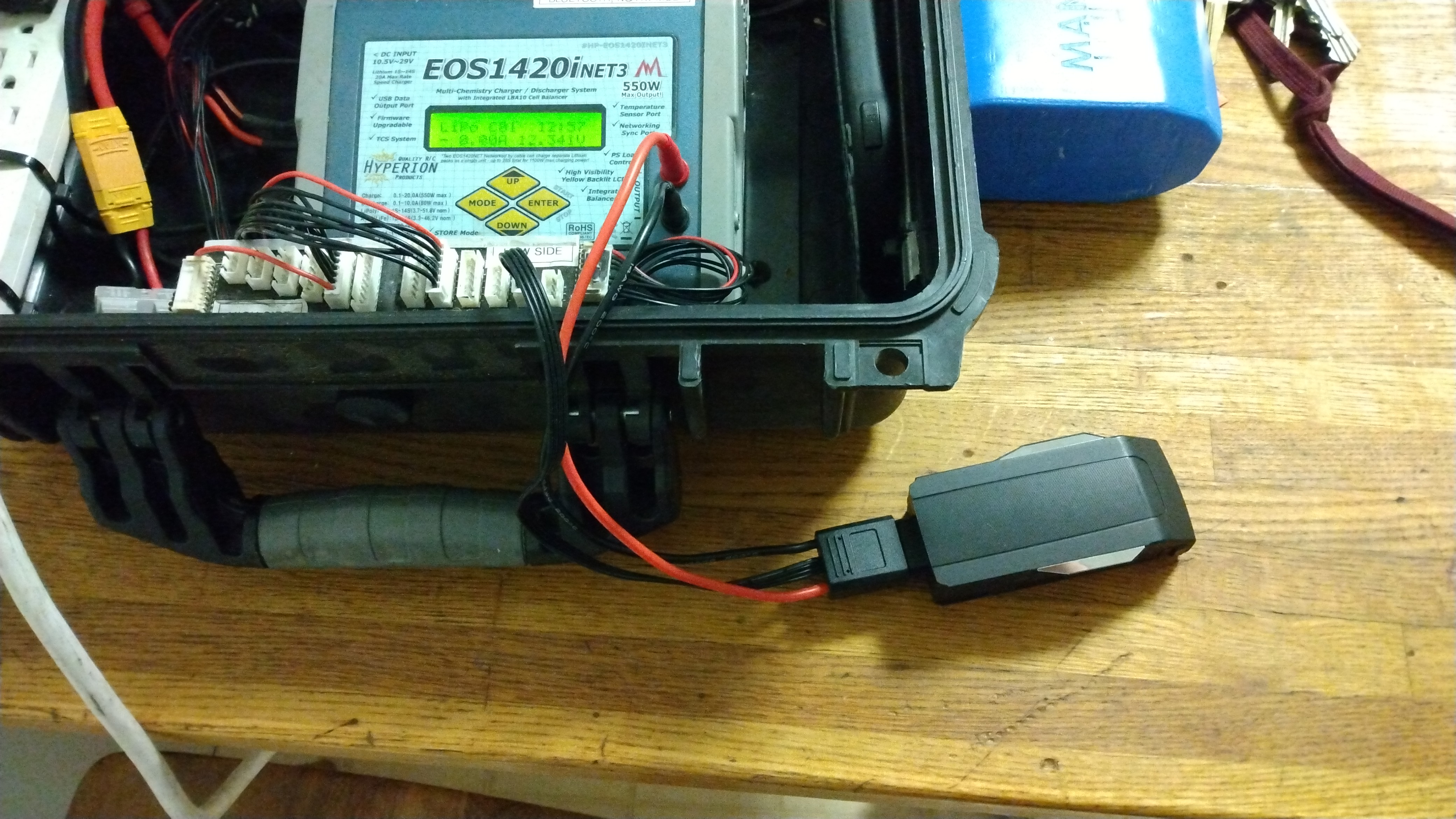 The GiFi power mantis-battery
interface connector is excellent, super straightforward.
For cycle testing I'm using a Hyperion 1420i with an
external Bluetooth connected tablet. One of the nice parts
about this particular fixture is automated cycling is
fairly straightforward. Shown is the GiFi adapter
connected to the stock mantis battery module. The GiFi power mantis-battery
interface connector is excellent, super straightforward.
For cycle testing I'm using a Hyperion 1420i with an
external Bluetooth connected tablet. One of the nice parts
about this particular fixture is automated cycling is
fairly straightforward. Shown is the GiFi adapter
connected to the stock mantis battery module. |
Stock
battery Discharge Plots 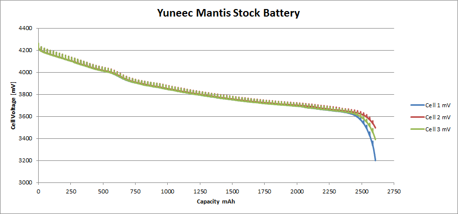 We get a fairly good picture of the
battery from these two plots. The cells seem fairly well
matched capacity wise and have a low impedance.
Interestingly i noticed that the stock charger pushes
these to 4.35v / cell. That's fairly high. While there are
LiHv cells its somewhat questionable, generally charging
non LiHv packs nets a slight increase in capacity at a
significantly reduced cycle life. My cycle test fixture
doesn't quite support LiHv, I can charge up to 4.3V /
cell. For capacity testing I opted for the normal 4.2v
charge, 3.2v discharged. We get a fairly good picture of the
battery from these two plots. The cells seem fairly well
matched capacity wise and have a low impedance.
Interestingly i noticed that the stock charger pushes
these to 4.35v / cell. That's fairly high. While there are
LiHv cells its somewhat questionable, generally charging
non LiHv packs nets a slight increase in capacity at a
significantly reduced cycle life. My cycle test fixture
doesn't quite support LiHv, I can charge up to 4.3V /
cell. For capacity testing I opted for the normal 4.2v
charge, 3.2v discharged. Some interesting points of note, I opted for a fairly mild discharge (1.5A) / charge (1.5A). One of the issues with unknown batteries is 'charge at 1C, discharge at 1C' doesn't quite apply as you don't know the actual capacity, sure we have a nameplate but its unclear how accurate it is. In this case we actually charged at 0.6C which is a bit low, part of this was due to the connector. In an ideal world we have a great 'kelvin sense' connection for each cell, where the cells voltages are measured at the cells and none of the charge / discharge current is present in the voltage sense wires. Unfortunately the battery is designed in such a way that the pack + and pack - are also cell voltage sense leads. By lowering the charge / discharge rate you can reduce the effect as the current is low and the associated voltage drop is also low. For some verification i We basically conclude the stock battery is 2.606Ah charged to 4.2v with a 35mOhm pack impedance @ 50% state of charge, weighing in at 191.6 grams |
3rd
Party Batteries: GiFi Power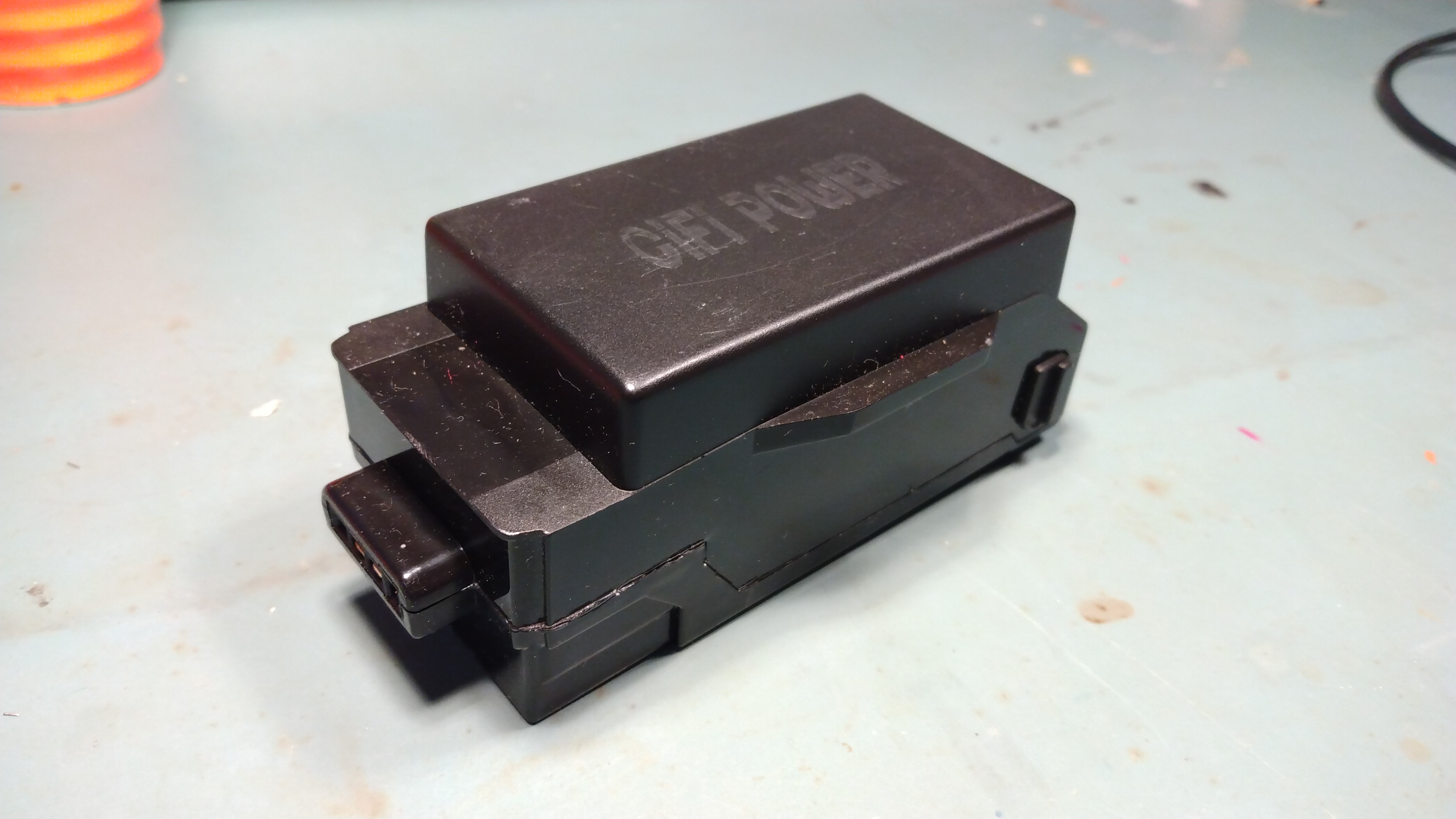 I did purchase a 3rd party pack, nominally to have a spare when heading out on a trip. The 3rd party battery I purchased is [link], interestingly it is mechanically taller (and higher capacity) than the stock pack. Unfortunately this means that the stock charger spacing is a bit tight, IE: you can fit 2x bigger packs or 1x big pack and 2x normal packs. Its actually assembled fairly well, you can disassemble it carefully with a small Phillips head screwdriver This module is listed as 3.9Ah which is a 25% increase in nameplate capacity. Curiously it only weighs 205.4 grams, which is a bit suspicious as we're netting a fairly large capacity increase for only a 6.7% battery mass increase. A bit suspicious. |
:/ GiFi battery
Discharge Plots :/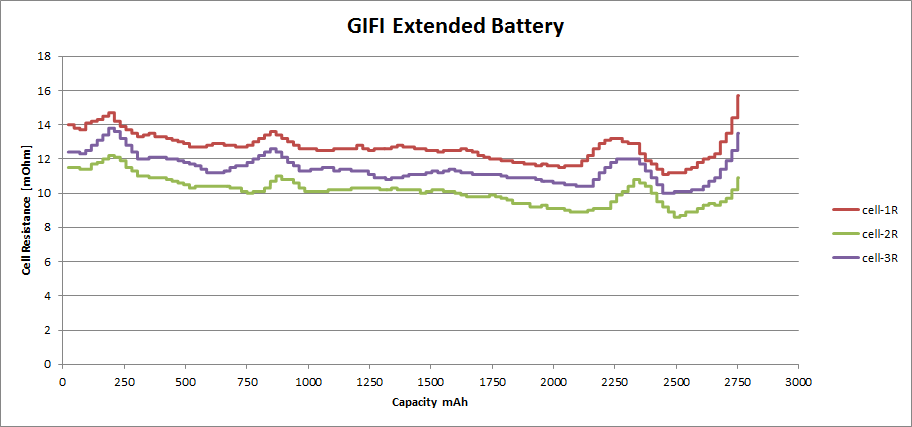 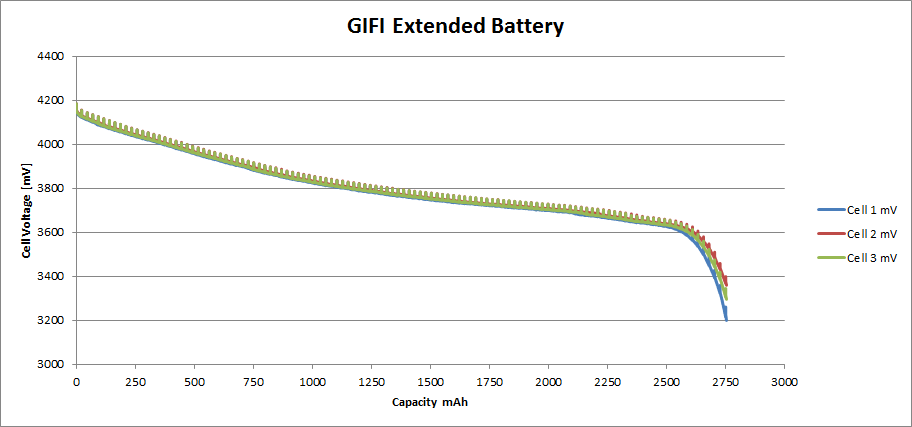 Using the same discharge parameters i
used on the stock batteries (1.5A charge, 1.5A discharge,
4.2v /cell termination voltage) we get the following
plots: Using the same discharge parameters i
used on the stock batteries (1.5A charge, 1.5A discharge,
4.2v /cell termination voltage) we get the following
plots: The capacity is not even close to the label, i get a whopping 2.754 Ah, not 3.9 Ah. I ran this three times and got nearly identical data. This is incredibly annoying as the GiFi pack is ~50 USD. The battery is well balanced capacity wise and fairly well matched cell resistance wise Just frustrating that it is no where near the nameplate capacity. |
Emailing
GiFi about some curious capacity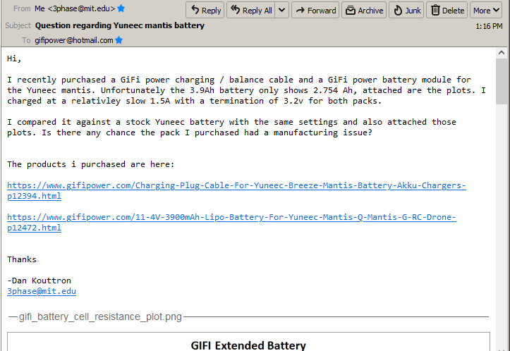 Not sure if I will receive a response, but I emailed the folks at GiFi. They have a fairly reasonable website with a contact form [link]. I'm going to give them the benefit of the doubt as this could be an older pack? Or maybe it was sitting in a hot warehouse? Lets open it up and see if there's any oddness inside, its possible there are some clues. |
GiFi-Power
drone pack tear-down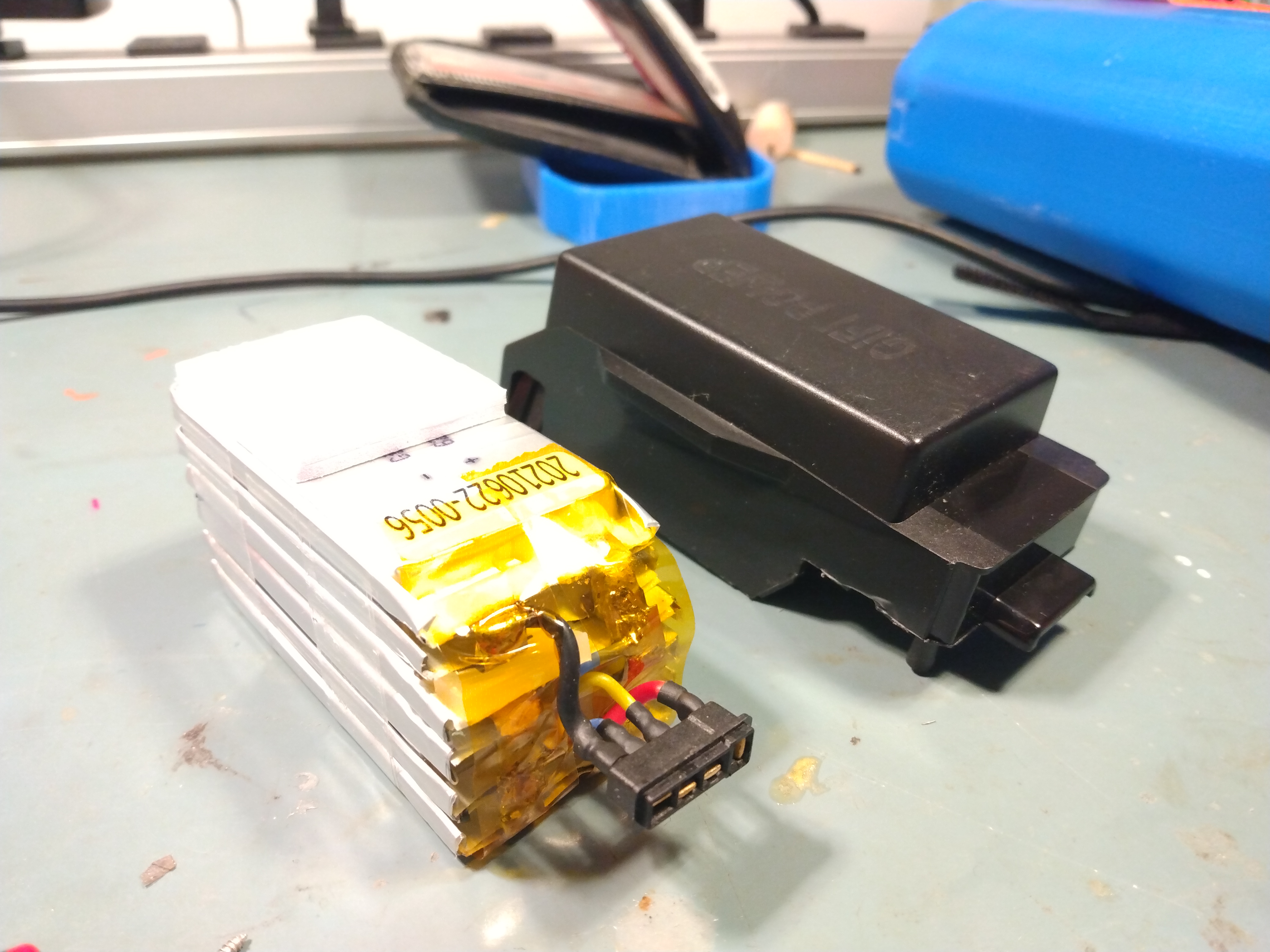 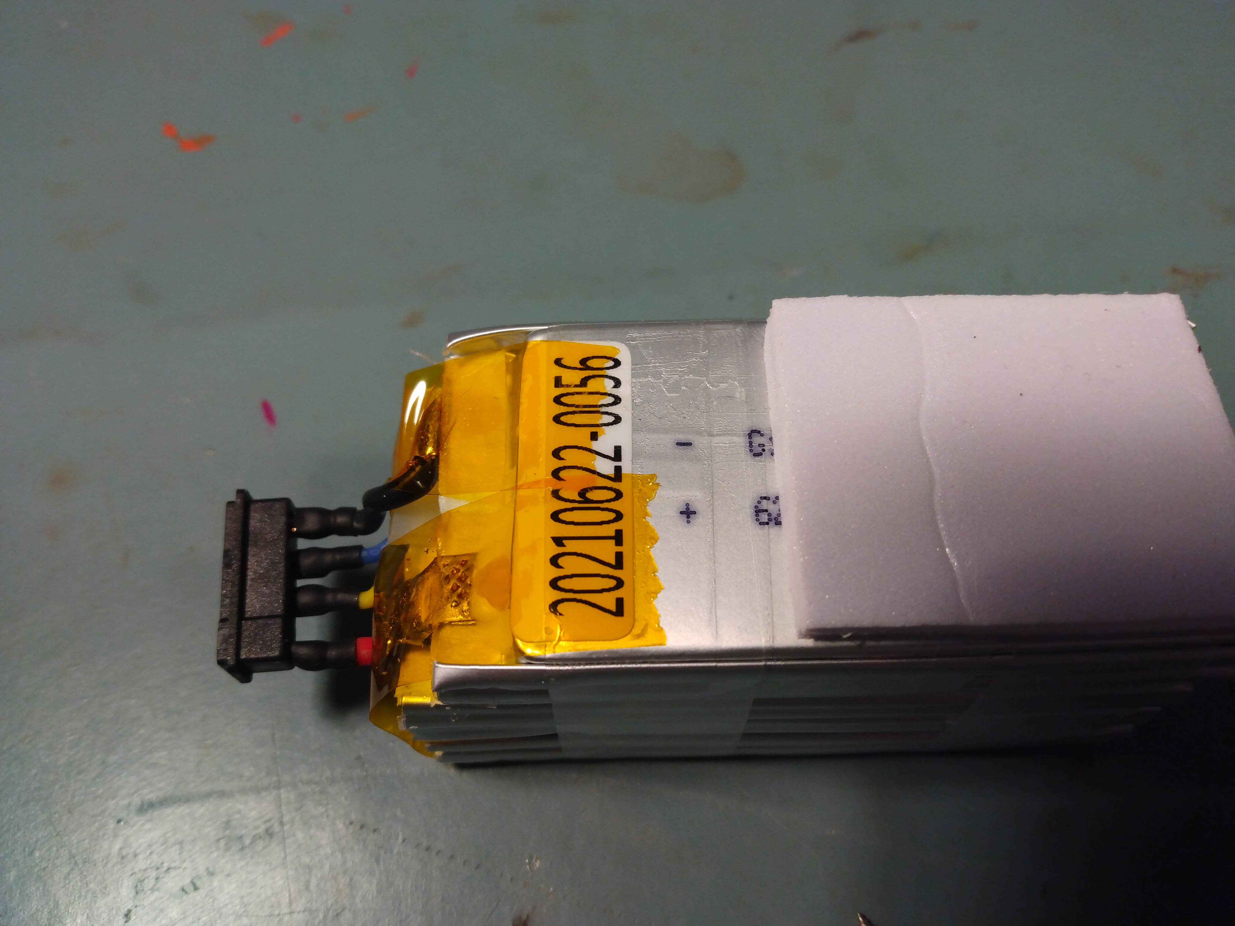 After removing the three self-tapping screws, the case comes off with a bit of force, we see a somewhat curious stack of LiPo pouch cells, Interestingly this is a 3S 2P battery module, where the top two cells are offset, possibly to aide in packaging? It is a bit odd, there doesn't seem to be a good reason as to why they couldn't be stacked all parallel. As you can see these packs are pretty simple, its literally cells and a connector. We do learn that inside there is a datecode-ish label, we can kind of guess this was made on June 22nd 2021. So its likely this was not an 'old' pack with lower capacity. |
I
really just want to make a DIY battery now -___-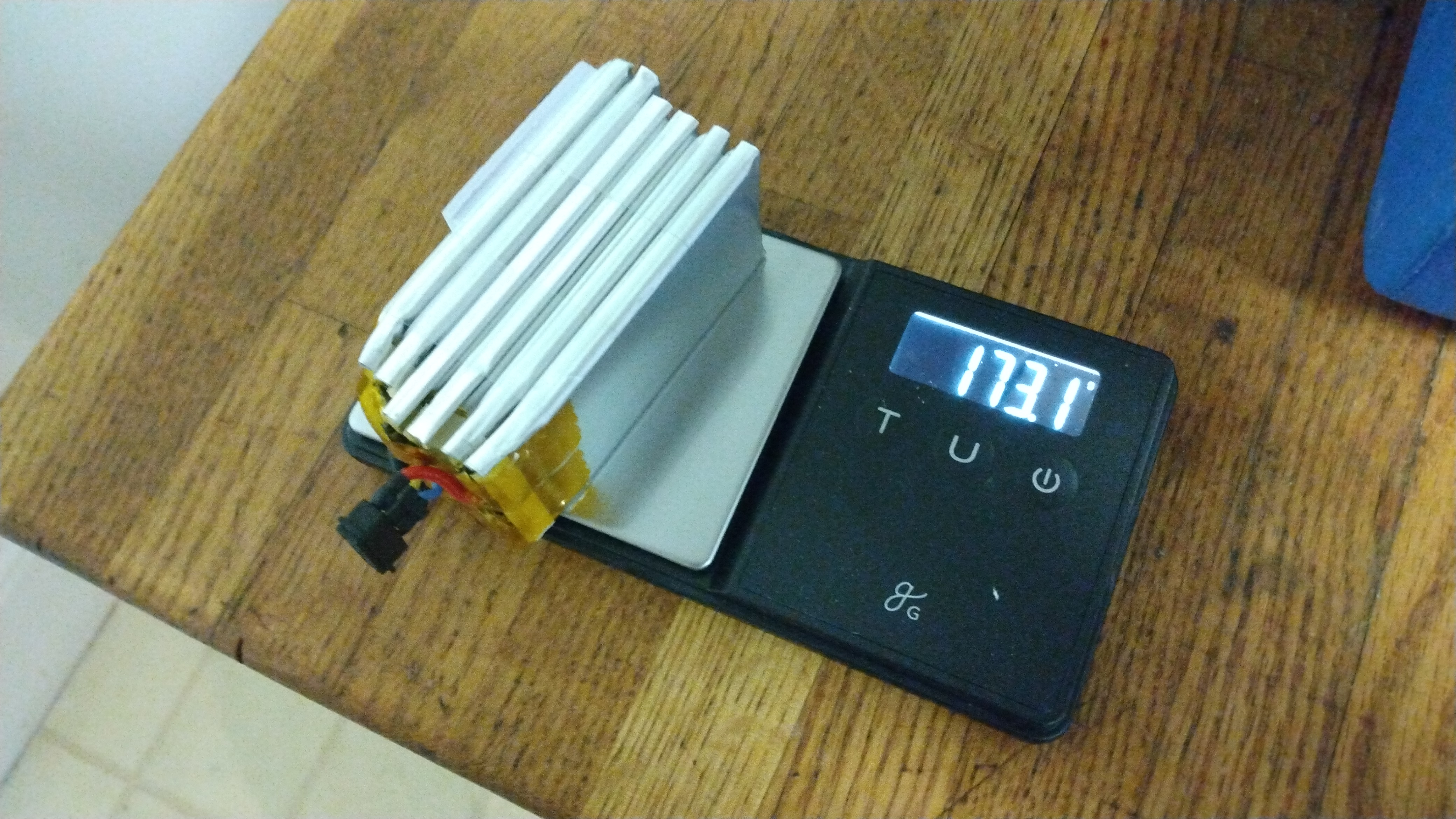 ~2.5ah is right in the range of
single-cell off the shelf 18650's, with some legitimate
Samsung 30Q's we could shove in ~3ah if they mechanically
and mass-wise fit. ~2.5ah is right in the range of
single-cell off the shelf 18650's, with some legitimate
Samsung 30Q's we could shove in ~3ah if they mechanically
and mass-wise fit.We do know the dimensions and mass of the stock and 'extended' pack, lets just rough estimate if an 18650 pack is feasible, mass / volume wise. Lets start with mass: we know that a 30Q is 48g, so without anything we're at 144g of cells. This is actually fairly good. we would need a printed case, but 144g + wire + connector + weld-strap is still reasonable, mass-wise, we may be able to do it for <210g. 18650's also have the advantage of 'not terrible cycle life'. One of the big issues with pouch cells is, due to a lack of mechanical containment, they balloon a bit and their resistance skyrockets. The mass of the GiFi power pouch cells + wire + connector comes in at 173.1 grams. each cell is 33.2 x 71.5 x 5.75 |
Lets
plot battery options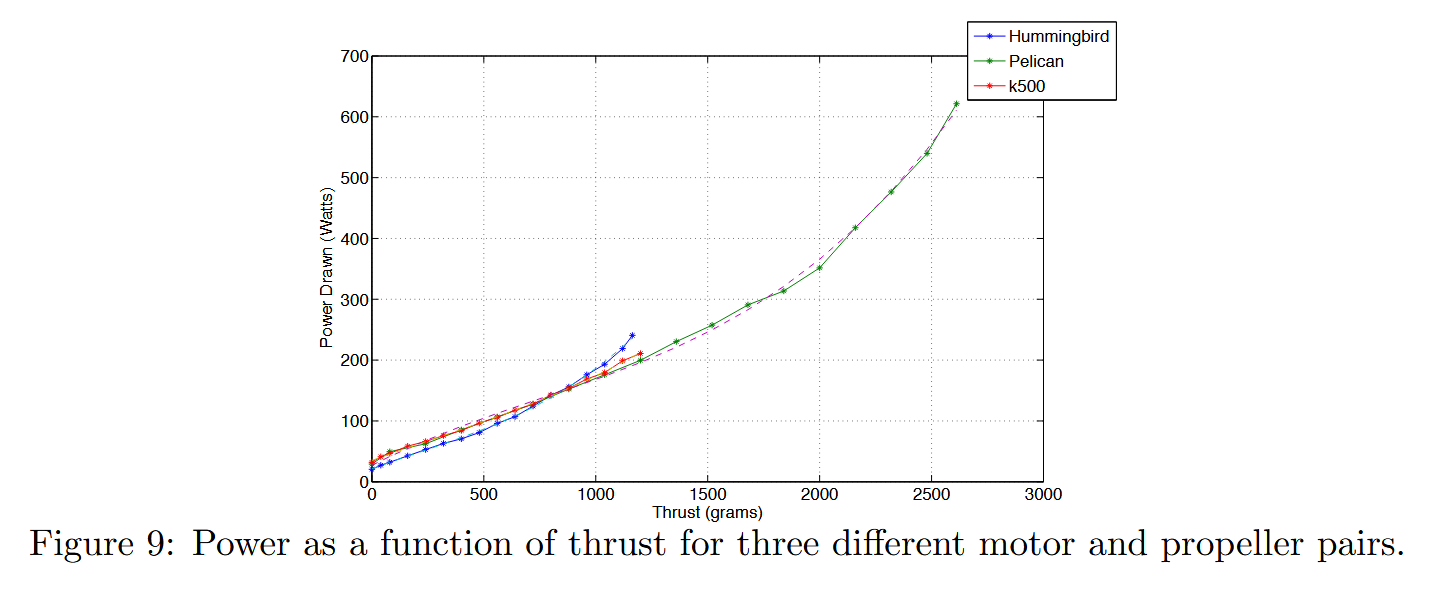 Drone battery mass is a really
non-linear thing, doubling capacity by doubling battery
mass does not actually double flight time, any increase in
mass on a small drone has a huge effect on run-time and
control authority. I wasn't really aware of how exactly
these were rated, but the paper "Power and Weight
Considerations in Small, Agile, Quadrotors [2014]" was a
really good start. From this plot we can estimate for a
500g drone at hover, we need about 100w. For a 3S LiPo,
(11.1v avg) that's 9A of battery current to hover. This
seems high but is possibly a good first order
approximation. Drone battery mass is a really
non-linear thing, doubling capacity by doubling battery
mass does not actually double flight time, any increase in
mass on a small drone has a huge effect on run-time and
control authority. I wasn't really aware of how exactly
these were rated, but the paper "Power and Weight
Considerations in Small, Agile, Quadrotors [2014]" was a
really good start. From this plot we can estimate for a
500g drone at hover, we need about 100w. For a 3S LiPo,
(11.1v avg) that's 9A of battery current to hover. This
seems high but is possibly a good first order
approximation. If we guess that the connector and wire are 10g, we're looking at: 163g of battery for 2.7Ah pouch cell 154g of battery for 3.0Ah Samsung 30Q 18650's 157g of battery for 3.4Ah LG Chem INR18650 MJ1's 214g of battery for 4.9Ah Samsung 50E 21700's |
Other
Yuneec Drone Batteries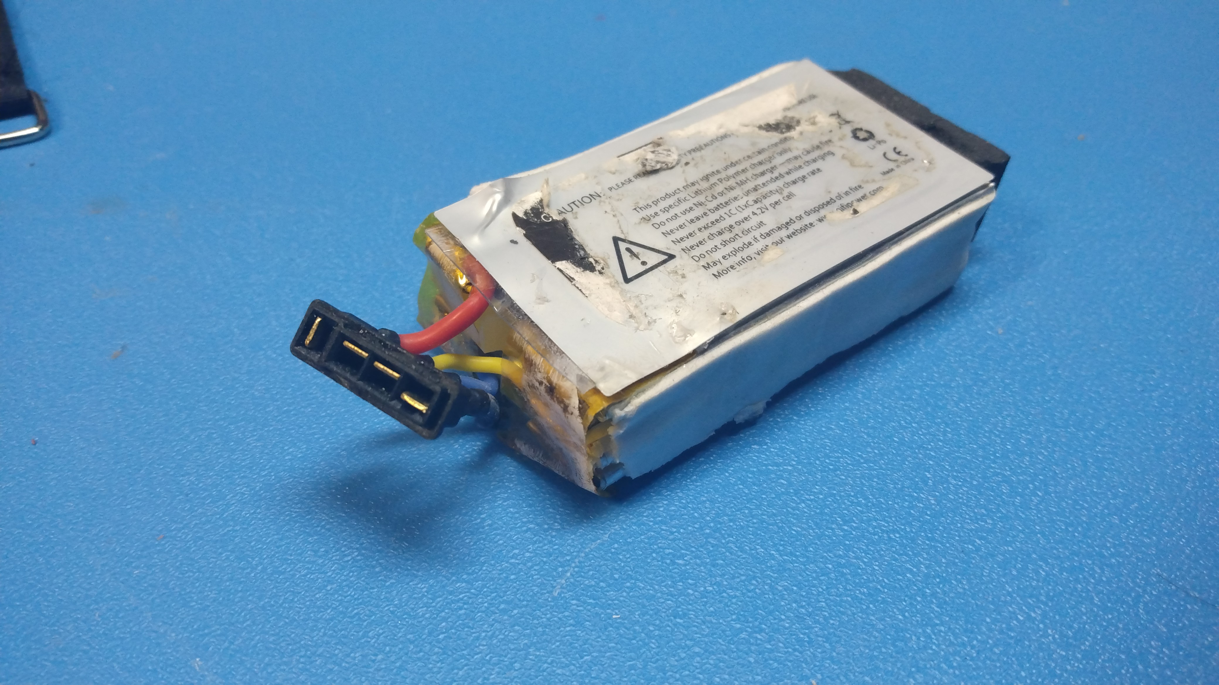 Interestingly both the Yuneec Mantis (G & Q) as well as the Yuneec Breeze use the same battery connector. The breeze is a smaller drone, so it uses a ~1ah pack instead of a ~2.7ah one. I found a low cost 'breeze' pack on eBay to harvest the connector and confirmed that they are indeed identical. It would be interesting to do a run-time test to get a plot between the breeze low capacity pack, the stock battery and the 3rd party bigger pack. At least now i have a host connector to make a prototype pack with. |
Back
to that connector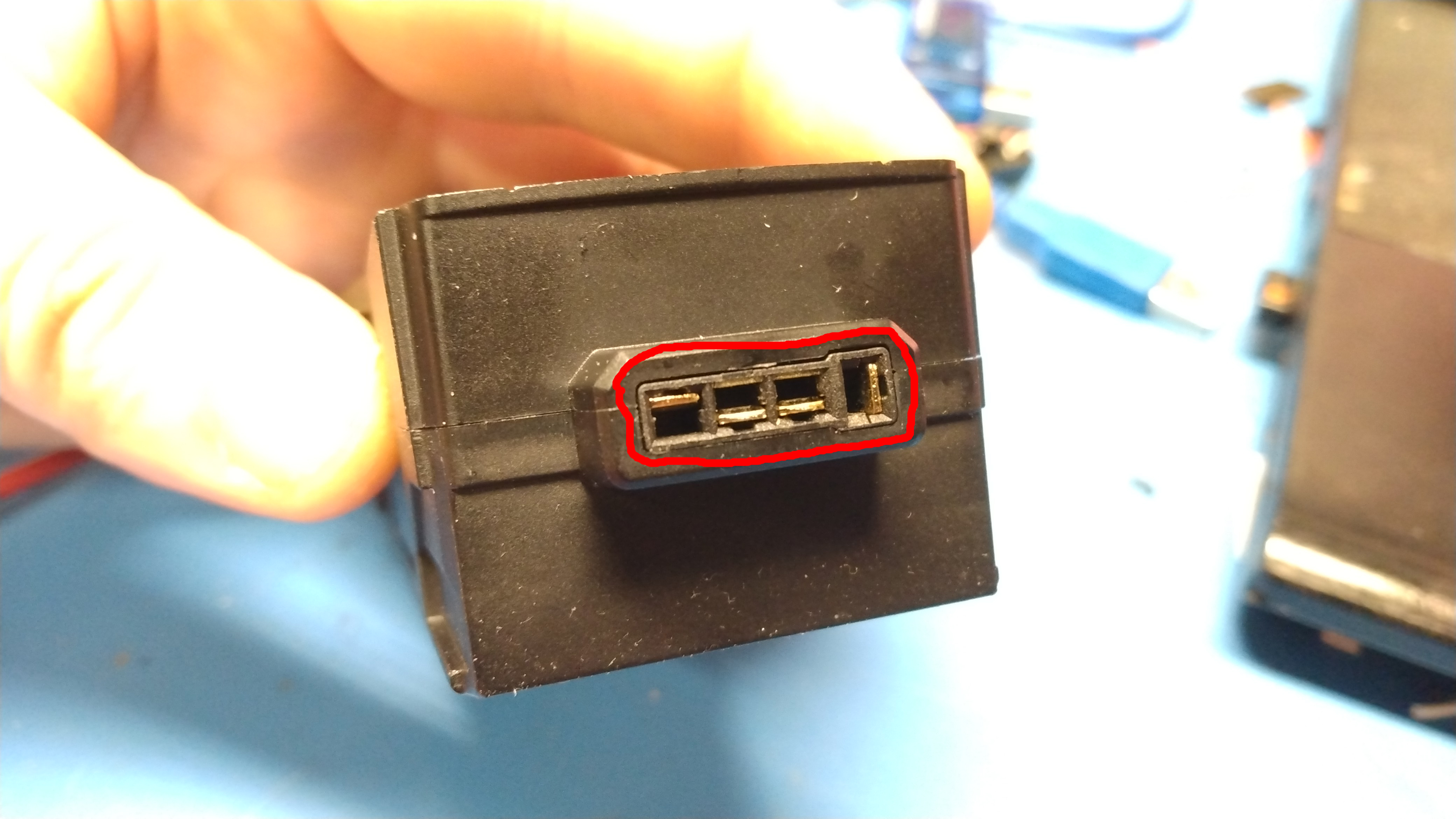 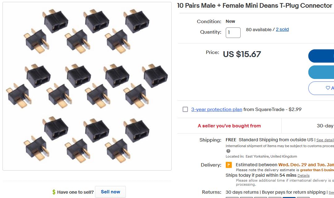 I've attempted to actually purchase this connector, but it doesn't appear to be available, even with jumping through language barrier hoops, at least at the time of this writing. Do you know what this connector does remind me of? Deans connectors, like somehow miniature Deans connectors. I never really liked deans connectors, as they make somewhat miserable wire-to-connector mates, and rely on heat-shrink to do wire-to-wire isolation. Is there a mini-deans? There is, and it's more common in the UK apparently. I ordered 10 pairs with the hopes of having the spring pin connectors being the same size as our mystery drone connector. Here's a link to the vendor [ebay link], shipping has been slow, looking forward to these appearing. |
| Mission planner and
hunting for mavlink |
Normal
Handheld Remote Command & Control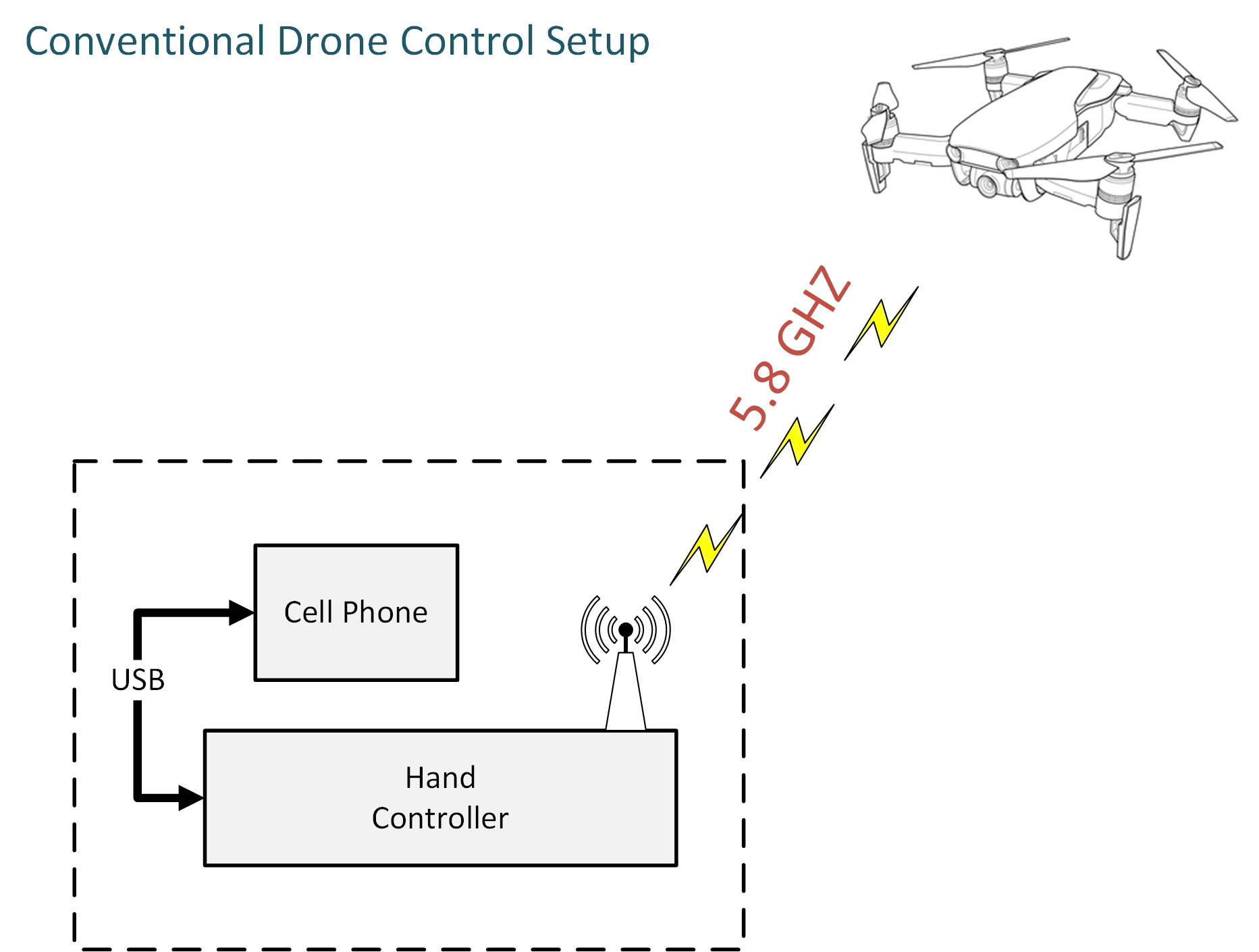 The normal setup is fairly straightforward, you have a hand controller it connects to an android phone via a USB-c to USB-a cable. The hand controller is doing all the heavy lifting, acting as a 5.8ghz bidirectional modem, sending commands out to the drone while also receiving telemetry and video. The Cell phone in this situation is mostly functioning as a display, but does allow for some course plotting, and limited touchscreen waypoint mission generation. Between the hand controller and the drone there's a pairing process, we're gonna figure out what that actually is doing |
Mission
Planner Command & Control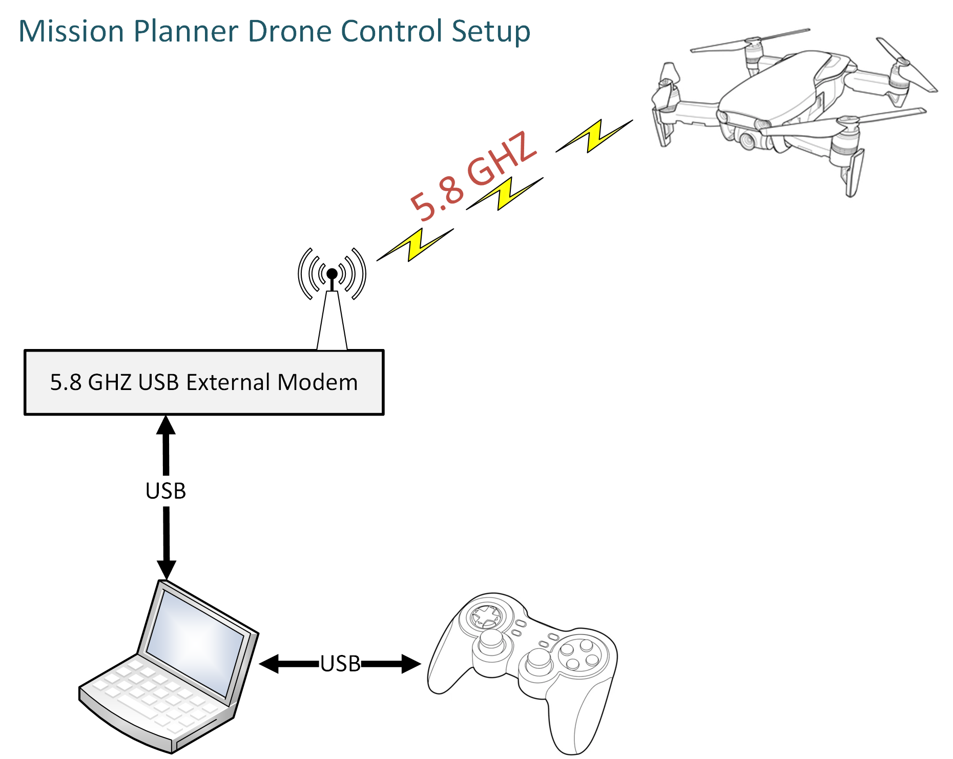 So here's where it gets interesting, instead of using the default setup we're going to connect to the drone directly from a normal computer, through an external 5ghz WiFi modem. If you've used 5ghz for WiFi in a residence, its great at short range but falls off quickly in comparison to 2.4ghz. Its a somewhat confusing choice to go with a 5ghz network link on a drone but either-way lets dig in. One of the interesting aspects of getting mission-planner setup, aside from being able to plan more complex way point paths, is to open up the option of adding external data packages, its somewhat visible on tear down photos that there are some communications ports broken out on the main PCB. Routing in external sensor data would be really interesting. This could be radios, this could be environmental sensors etc. That's fairly exciting. Put an air particulate monitor payload and map PM2.5 pollution, put an esp32 with a directional 2.4ghz antenna and spatially map a radio band. Are CO2 sensors accurate enough to see deviations near residences? Does propeller wash make the data useless? I checked out digikey's gas sensor page [link], maybe a low PPM CO2 sensor could actually work. |
 I initially got interested in this
drone as it's listed on the pixhawk page as a compatible
drone [link],
curiously it doesn't seem that well documented. It looks
like i confused 'runs a pixhawk' with 'also open source
and documented'. ARGH I initially got interested in this
drone as it's listed on the pixhawk page as a compatible
drone [link],
curiously it doesn't seem that well documented. It looks
like i confused 'runs a pixhawk' with 'also open source
and documented'. ARGHIt looks like Yuneec's larger industrial drones are more documented and it's assumed the flight controller for the smaller consumer sized ones are the same. This thread [link] indicates that only the Yuneec H520 appears supported, but it's likely that they all use the same flight controls. Some further details here [link] indicate that it somewhat supports mavlink but there's issues. INTERESTING. There's somewhat active forums that are Yuneec specific here [link]. This post somewhat shows QGC working [link], maybe its time to write a guide. Somewhat more info here [link] [link] but there doesn't seem to be a quick-start guide. Time to make one? |
Step
Zero: Does the drone show up at all using a
laptop? 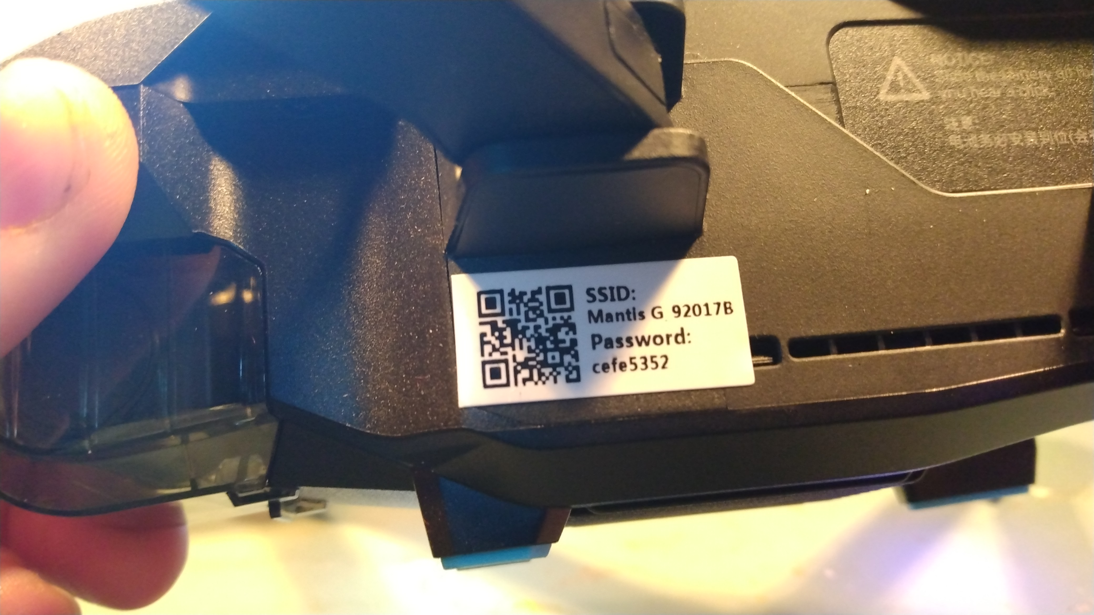 Before buying a nice external USB WiFi card, we can get a hint as to what the drone is doing with just a laptop equipped with a 5gHz internal radio? Well that was answered quickly, yes it shows up after 90 seconds on the normal windows network scanner. Ok well this is a great first step. The WiFi login is on a sticker under the folding wings. Previously i never gave this much attention as i thought it was a phone-pairing thing. Either way I was able to connect directly to the drone (acting as an AP), time to do a portscan and learn some more about this monster. One thing to note is the mantis does run a bit warm during this debugging phase I actually had it sitting next to a small fan to keep it cool. I think that during normal operation the prop wash helps keep the electronics cool. |
Zenmap
and open ports 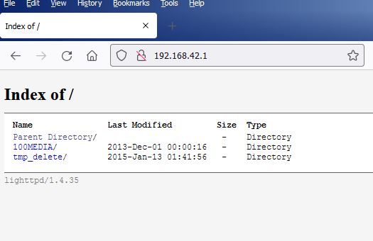 Zenmap [link] is a cross platform gui for nmap, a networking tool that helps identifying network topologies as well as information about network ports. The first thing we learn from connecting to the drone's access point, we learn that it's IP is 192.168.42.1 This seems to be the default for both the Yuneec Mantis Q and G models. Port 80 is an apache-like webpage, you can grab the recorded footage and images directly in the browser. |
Ok
lets do a port scan and see what ports are open for
communications. 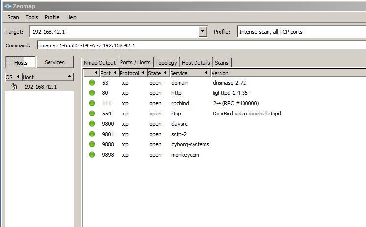 I fired up a copy of zenmap which is a GUI wrapper for nmap. Interestingly i had tried a quick scan but the 9000 series ports were not listed. So what do we have so far:
I don't know yet what port 9800, 9801, 9888 or 9898 are
doing. We can cheat and see if putty can display these
in raw-mode.
I was somewhat expecting mavlink activity visible on
one of these |
Oh man
is that RTSP port, just raw RTSP?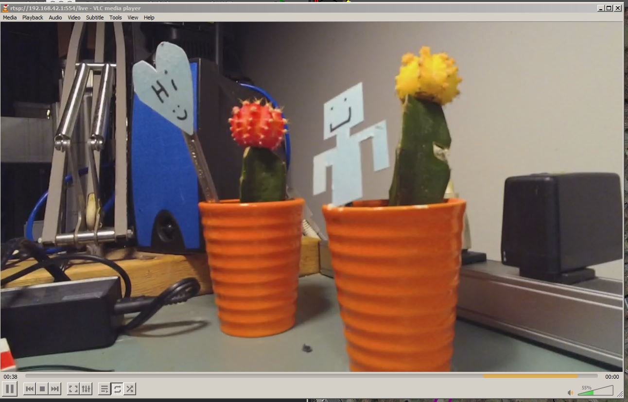 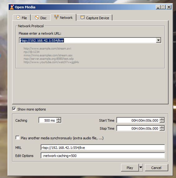 RTSP is a mechanism for sending raw
video, and while there are many codecs and resolutions,
its a fairly well documented protocol. To test this i
fired up VLC, opened the network streaming tab and plugged
in the drone's details. RTSP is a mechanism for sending raw
video, and while there are many codecs and resolutions,
its a fairly well documented protocol. To test this i
fired up VLC, opened the network streaming tab and plugged
in the drone's details. I wanted to point VLC at the drone's ip address (192.168.42.1) and point it at the RTSP port (554). I tried just the ip:/port but it did not immediately work. I then tried /stream and /live and /live worked! While connected over wifi, you can pipe the main camera video (720p 30fps) directly to VLC, this is amazing! Say hello to my lil cactus's |
Wait,
is mavlink just sitting there, open and ready to use?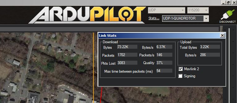 Curiously zenmap did not portscan the
full port range, so i did not quite get the full picture
of some of the higher # ports. I did some digging and
14540 is used for mavlink on some of the other Yuneec
drones. I selected UDP for communications, entered in the
drone's IP and then added in port 14540. Curiously zenmap did not portscan the
full port range, so i did not quite get the full picture
of some of the higher # ports. I did some digging and
14540 is used for mavlink on some of the other Yuneec
drones. I selected UDP for communications, entered in the
drone's IP and then added in port 14540. WE HAVE COMMUNICATION WITH MISSION PLANNER. This is fairly wonderful, while there are some errors, I am getting raw battery volts and live plots from accelerometers. |
| rtspsrc
location=rtsp://192.168.42.1:554/live ! application/x-rtp
! rtpjpegdepay ! videoconvert ! video/x-raw,format=BGRA !
appsink name=outsink |
| You can use Q Ground
Control ( QGC - QGroundControl - Drone
Control ) You'll need a laptop with 5 GHz Wifi (built-in or get an USB Wifi) Connect laptop to Mantis Q Wifi AP ( Mantis_xxxxxx) and QGC will discover and connect. Configure Video Stream to rtsp://192.168.42.1:554/live |
Can
you mission planner *AND* use the stock hand
controller?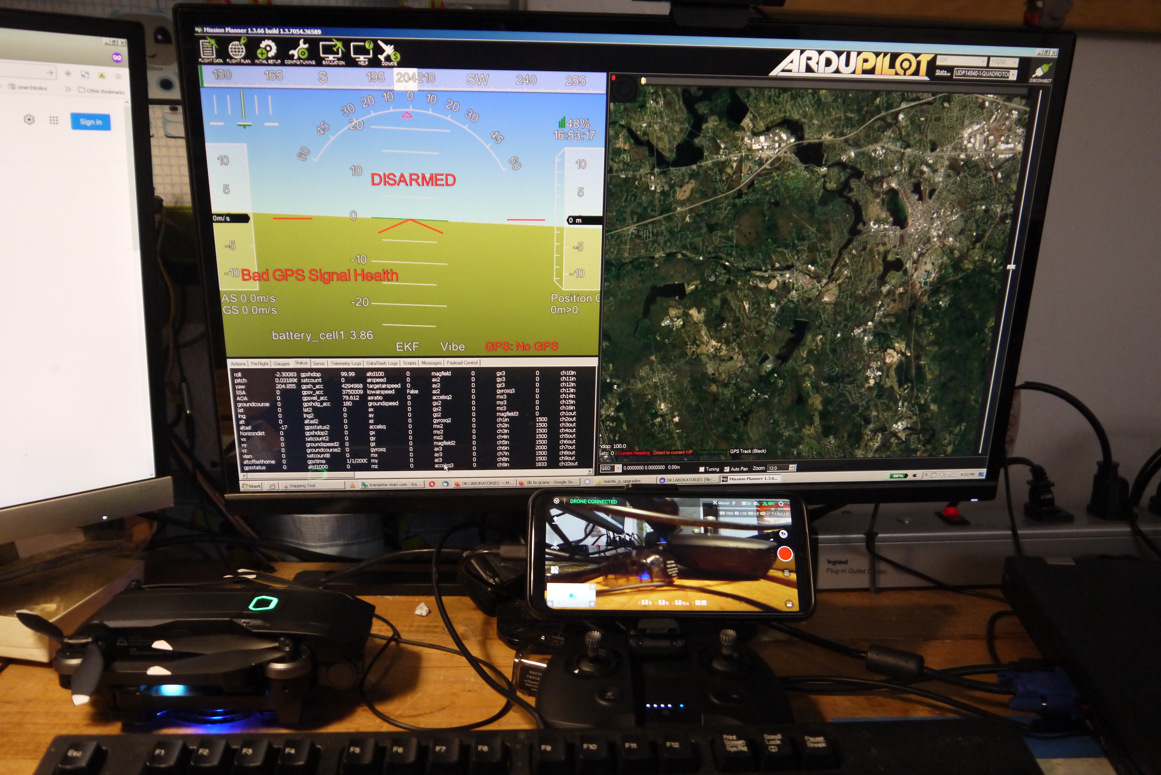 Kinda? I was surprised this even worked, but i was able to start the stock hand controller, connect to the drone as is normally done, then connect mission planner to the same UDP stream. This just worked I did also try to start a flight at the time, indoors without GPS reception, but was getting some issues. Shown in the photo (right) is both the hand-controller+phone connected to the mantis as well as a laptop over its standard 5ghz wifi internal card. Telemetry was showing up and everything! Is this a good idea? Honestly not sure. I'm trying to figure out if there's a 'listen only' mode for missionplanner but couldn't quite discern if that exists. |
Step
one, find some hardware:  To use a normal PC as the command and controls, we're gonna need a good 5ghz radio, I initially went looking for an Alfa AWUS036AC, ALFA's have been fairly reliable, but it was also hard to get quickly. The local micro-center had a TP link 5ghz compatible radio on a USB extension that may work. While laptop WiFi for 5ghz exists, I've found my antennas on the W530 are somewhat mediocre, and for 5ghz a good antenna really goes a long way. We're also going to need a controller to pair with QGC, my favorite 'really basic rectangle' is the Logitech F310, its simple and USB connected. No pairing issues, no forgetting batteries, its' kinda basic but works. Also available at Microcenter, if you remember way back I use this for SCARA robot control in linuxcnc. |
| Step two, get some
communications up and running: Ok |
Step
three: Pick a nice open, quiet place to debug and test While we'd all like a nice sunny day outdoors with WiFi and calm weather, I decided to sort this out for some reason the middle of the winter in Boston. I found a deserted overflow parking lot near a public park, with a park bench table and a built in charcoal burner thing for outdoor cooking. OK so I'm going to have warmth and at least some grilled food :] There are some nearby trees so its not quite super spacious but its secluded enough (and far enough from an airport) for this to work . I checked with [b4ufly.aloft.ai] to make sure there were no FAA restrictions. I requested permission for some limited low ground activities from the parks department and was granted permission. Technically you need a permit, but written permission appears to be a permit. The rules keep changing and are increasingly poorly documented, the ground where you can launch from can be restricted by the landowner, but the air is under FAA jurisdiction. <rant> If i launch while holding the drone have I launched from the ground? It's incredible, you're blanket not permitted to use a drone in parks in NH (the freedom state). Is a rover a drone? Is a 1995 RC plane a drone? </rant> |
| Whatcha
Bench Bro |
| Whats the possible
payload of this lil contraption? To test this I cut out
some 'weights' out of aluminum and flew while taking
observations of any signs of issues. This is easier to
test indoors flying with only optical feedback. |
| Plotting
a Sensor Package |
Drone
sensors, CO2 PPM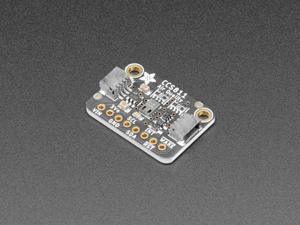 I've used a small Adafruit dev-kit CO2 sensor [CCS811], but I had some issues, namely a fairly slow warm-up time and a fairly high time before first-measurement (the minimum was 400ppm co2). I checked out [CO2 Earth] and holy crap we're at 400+ ppm as the average atmospheric CO2 reading for earth. @_____@ what the heck that is incredibly high. I think regardless of how it's implemented the gaseous measurement should assumed to be ratio-metric on a drone application, the sensors may be +/-0.5% but its not totally clear what forced air or turbulent prop-wash does to the accuracy of these readings. Initially I was interested in the Amphenol T6713 module [link] its smallish, has documentation, is priced at ~75$ and claims +/-3% accuracy from 0-2000 ppm. Why go all the way up to 2000 ppm? Good question, I'm not totally sure what effect home exhaust systems will have as a drone flies over, etc. Lets take a look at the datasheet [local copy] |
Datasheet
Review: Telaire T6713 CO2 Sensor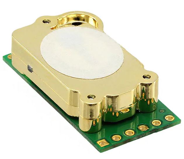 Quick datasheet notes:
Dane's review: |
Lets find
a particulate sensor, preferably on an evaluation board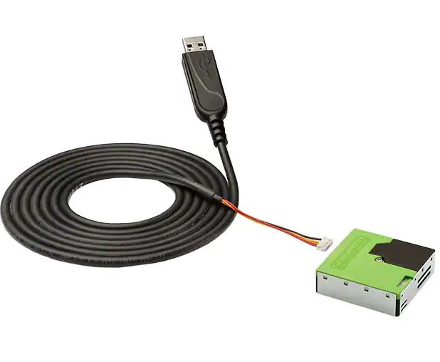 Particulate monitoring may be interesting and possibly less fiddly than CO2, the SPS30 from Sensirion looks interesting [spec-sheet] [datasheet] [local datasheet copy]. Lets take a look:
Mounting this on top of the drone may be a good plan, as it keeps it out of the prop wash. It may be possible to do a comparison test at ground level. With the drone sitting on a ladder a few feet above the ground, measure PM1, 2.5, 4, 10 for a short duration, then spool up props, measure, then hover and measure. By starting off the ground, hopefully ground level dust that could be kicked up from the prop wash is minimized. |
Did you notice the lack of advertisements or Facebook nonsense? Consider sending a cup of coffee :]
- I had no idea how much fun a portable drone would be. the
ability to go hiking and get some stellar shots from above, or
even have something that I could bring along on a plane ride
is excellent. This fits in a hiking backpack and survived a
hike up a few mountaintops already
If you have questions or comments, ask below or send over an email.
| Comments: |
|
HTML Comment Box
is loading comments...
|
Pack your homemade drone batteries safely, less they become inadvertent lithium hand-warmers.
Dane.Kouttron
Rensselaer Polytechnic
Institute
Electrical & Electrical
Power
631.978.1650