Dane.Kouttron
Quick Power Supply 'update'


<This
project requires further documentation>
Hardware:| Component | Purpose | Image |
| parallel lcd | Simple Cheap lcd Character Display. HD44780 Compliant. Found in unknown state | 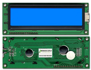 |
| atmega 48 | Super Cheap DIP Microcontroler. Programmed with AVR ISP MK2. Tacked to a protoboard. | 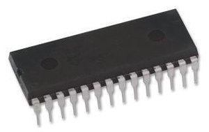 |
| 7805 | linear regulator | |
| Misc Components | Resistors, Caps, led, potentiometer (10K) |
Build:
| Component | Purpose | Image |
| Routing the outputs | For
some reason the outputs of the
supply were in the rear, some low gague wire and scavenged banana jacks
later, they were re-located to the front. The supply was also mounted onto aluminum risers to allow proper ventilation, the probably source of the failure of the previous supply |
 |
| Finding Some Power | To
drive the lcd,
microcontroller i will need 5v. After some trace-following and careful
observing, a low voltage winding from the main transformer was
rectified and dumped into a 2200uf cap. nominally, the cap stayed at
10V DC. Upon probing the cap, i found that there was little AC ripple.
Next i made some assumptions and tested them. i banked on having the
lcd and micro would consume 100ma at 5V. to simulate this (from the 10V
cap) i used a xxx ohm resistor. THIS
IS IMPORTANT. I checked that the power supply preformed well
with this extra internal load. There was no observable difference in
the power supplies output, even under load. I now had 10V, one 7805
away from a stable 5V supply. It is also important that the ground of the cap is the same as the ground of the supply output |
 |
| Testing the LCD | As
this LCD was
found in an unknown state, it was a good idea to test to see that it
worked before designing everything around it. Emily K was nearby, thus the lcd statement. LCD is driven in 4 bit mode (instead of 8 bit mode). Contrast was set by small blue potentiometer (as seen behind lcd screen) |
 |
| Operating at Higher Voltages | The A/D on the AVR is 5 V tolerant, not 55V, a simple resistive divider from the output of the supply was used. Note at this point the lcd was temporairally mounted into aluminum rectangle-bar. |  |
| Calibration | A multi-meter (outside of image) was used to calibrate the multiplier used to convert ADC counts to Voltage outputs |  |
Schematic / Setup:
| Linear reg supply | ... |
| Micro | ... |
Dane.Kouttron
Rensselaer Polytechnic Institute
Electrical & Electrical Power
631.978.1650