Dane.Kouttron
[3.1.17] Awakening an Old Robot, For Art
 OK, GOT AN OLD
ROBOT, AND WANT TO BRING IT BACK TO LIFE, (and make
some art) OK, GOT AN OLD
ROBOT, AND WANT TO BRING IT BACK TO LIFE, (and make
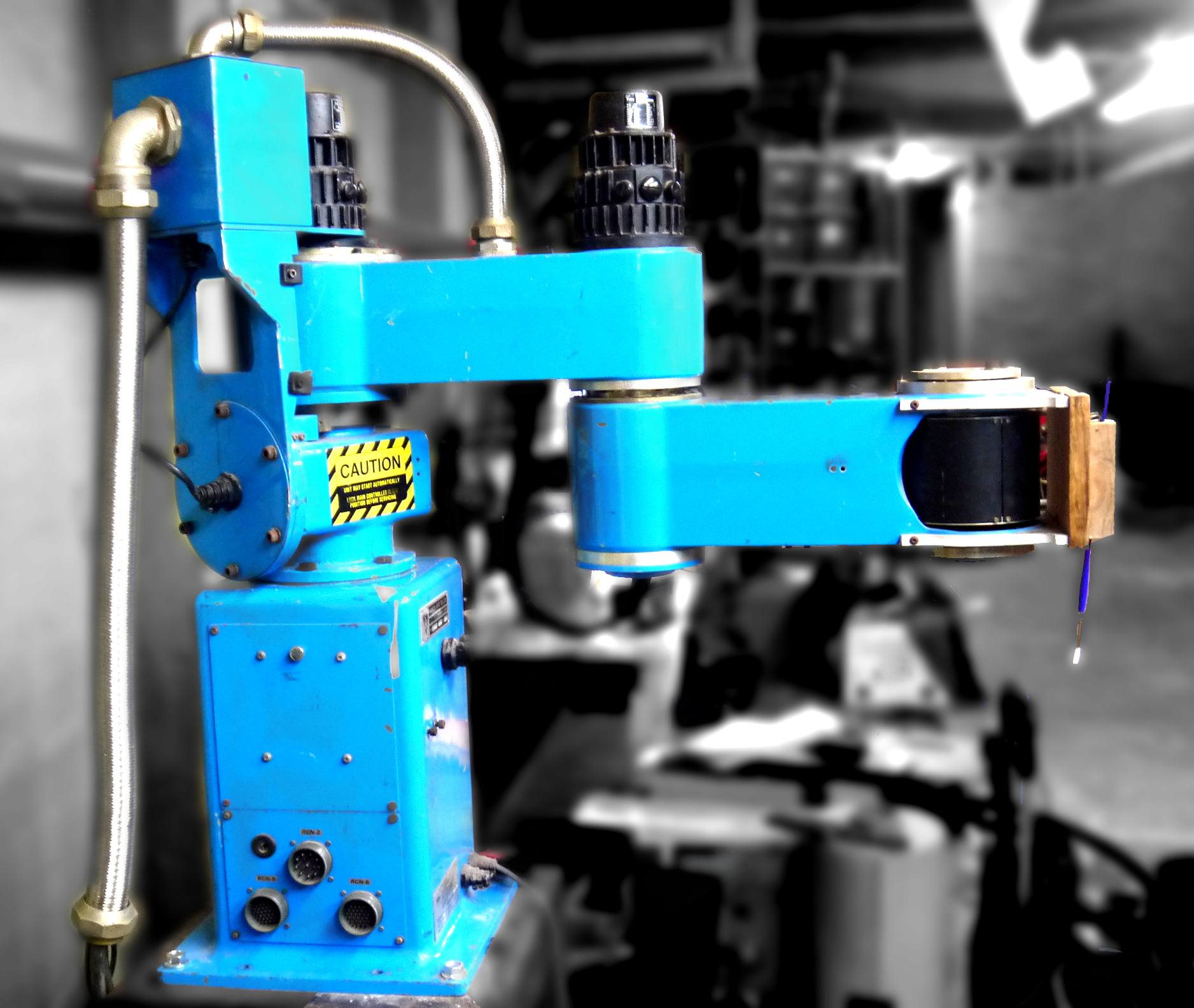
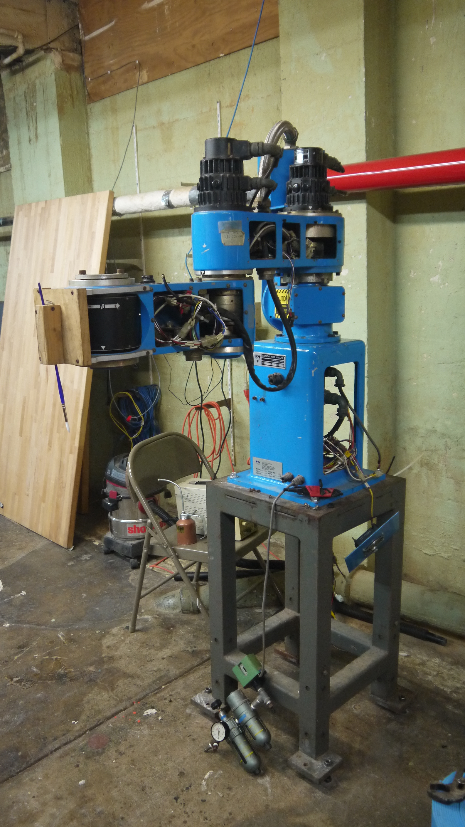
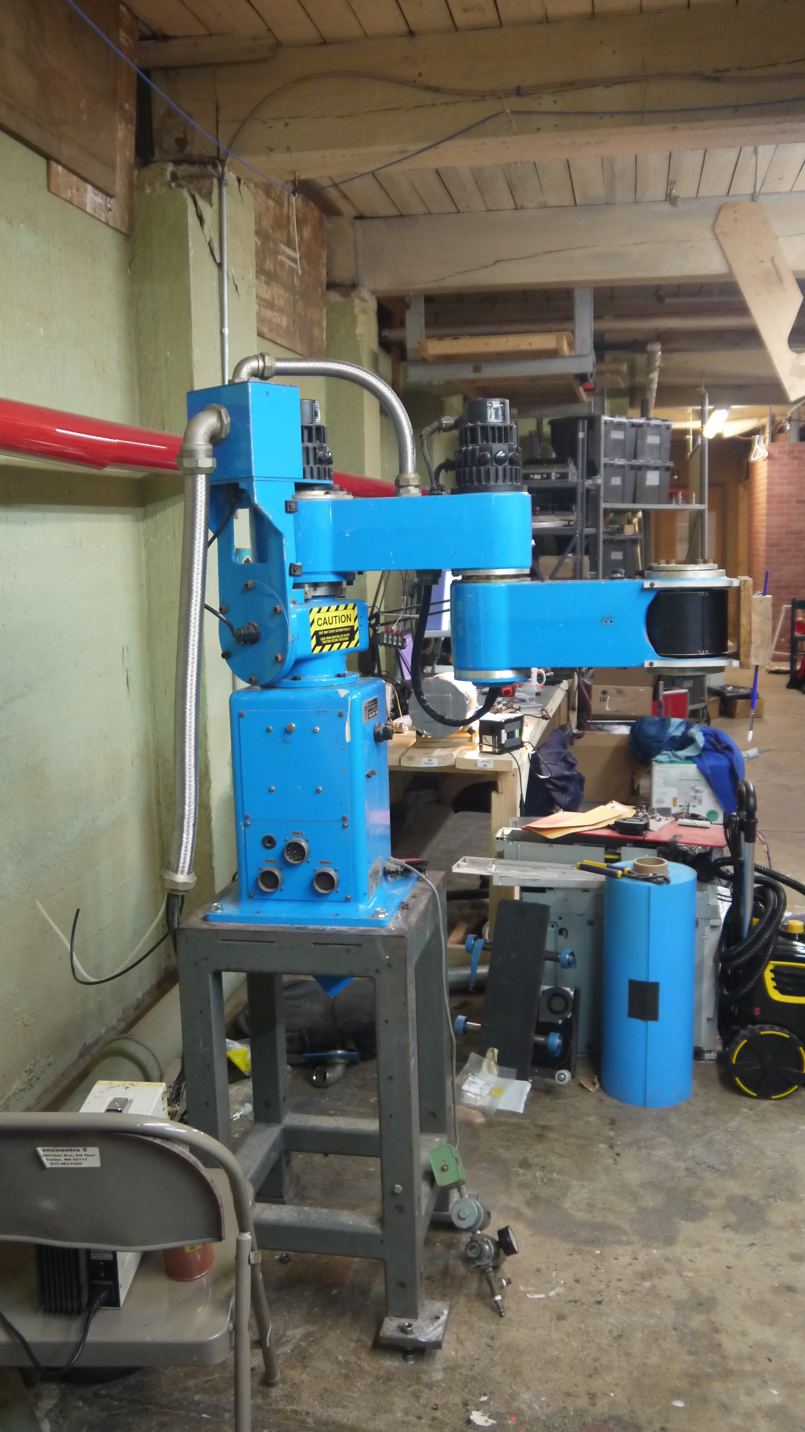
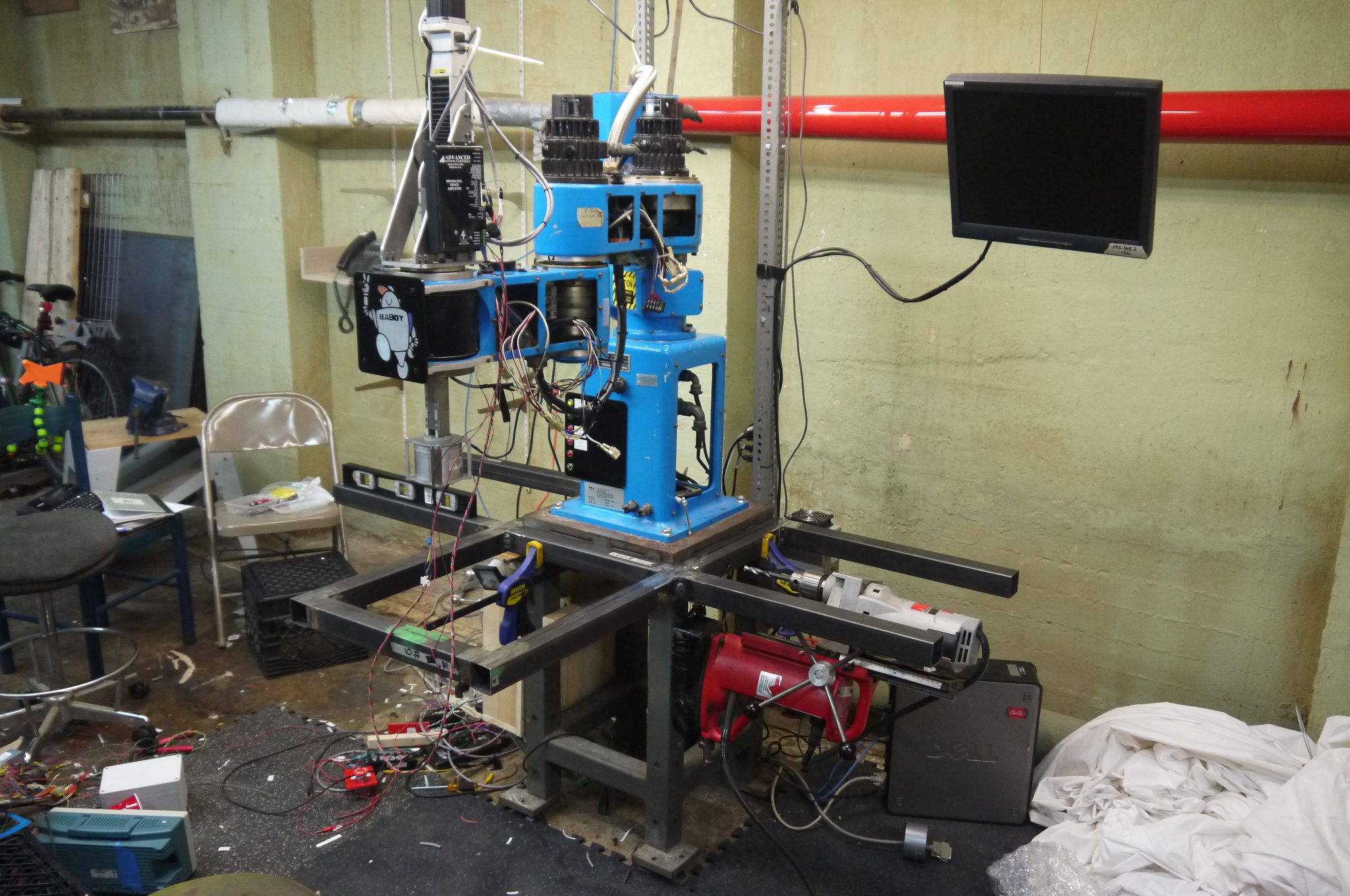
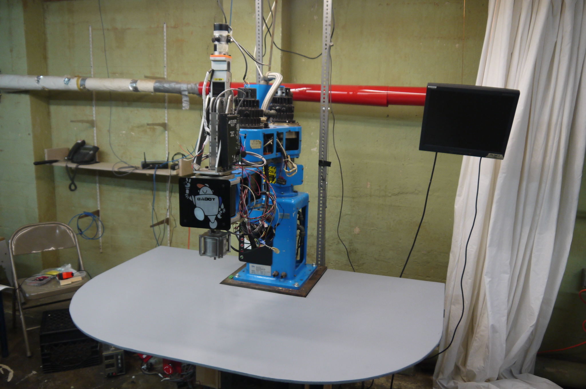
some art) WHERE TO START? BLUEBOT is a Japanese Dainichi Kiko 'PT-300H'. Born sometime around April 1983, Its a 'scara' style robot with three theta axes. Its heavy, and its somehow able to keep 0.1mm repeatably (3.9 thou) at full extension (28 inches). Each of the three thetas has a brush-dc servo and a 500 count / revolution encoder. The robot itself was gifted to the cause by some excellent MIT alums. With the help of some great comrades, it was dusted off from a basement, reverse engineered and brought back to life. Follow along for the trials and tribulations of waking up a robot and putting some zip back into its axes. |
| What? |
Archelogical Research |
New Mechanicals |
Control Hardware |
Power Electronics |
Z-Axis | Linux
CNC |
Wireless Controller | Lighting | ART !!! | Image Processing | Video | Bill
of Materials |
Conclusion | Downloads |
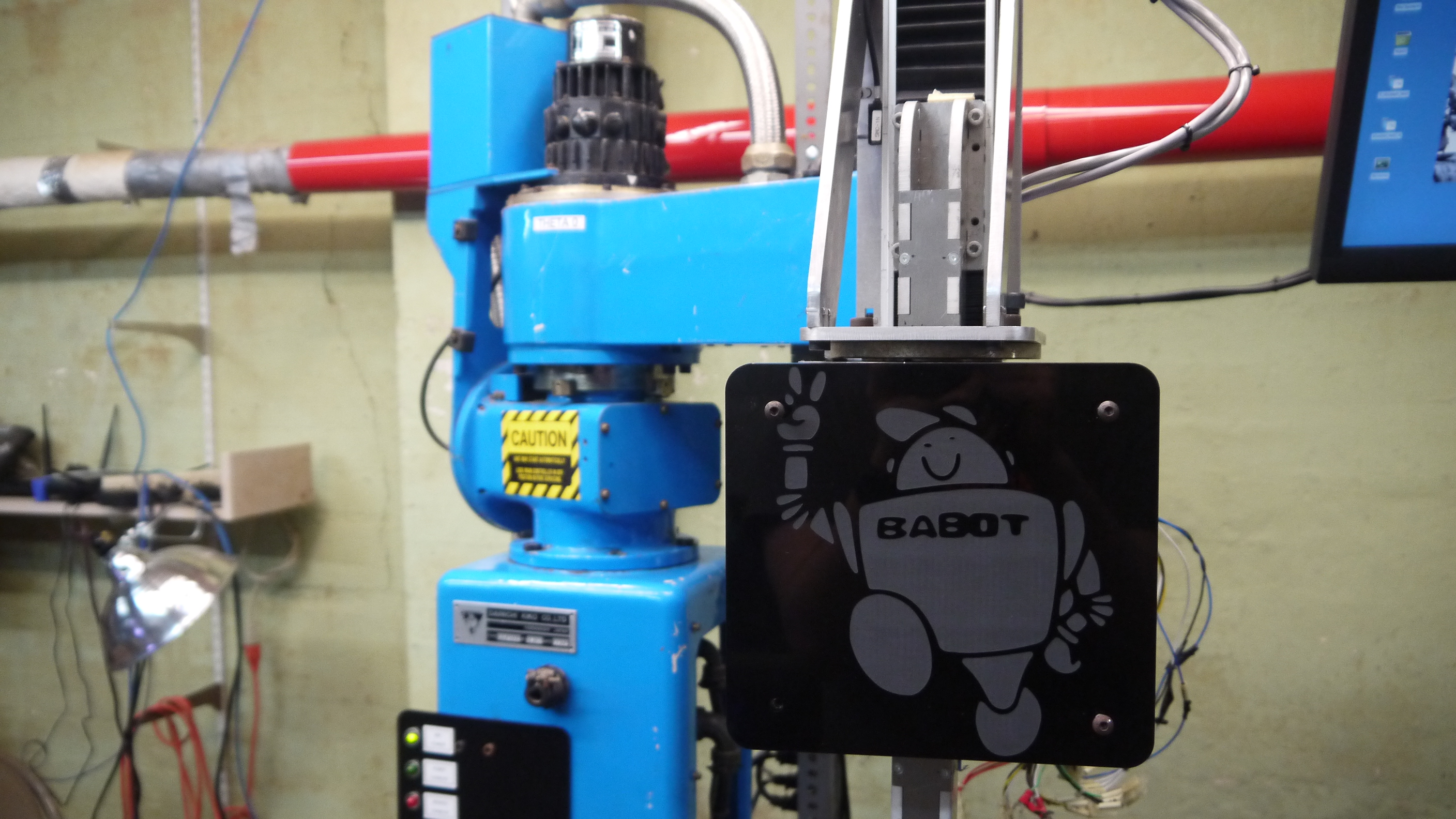
| A robot that can ART? | |
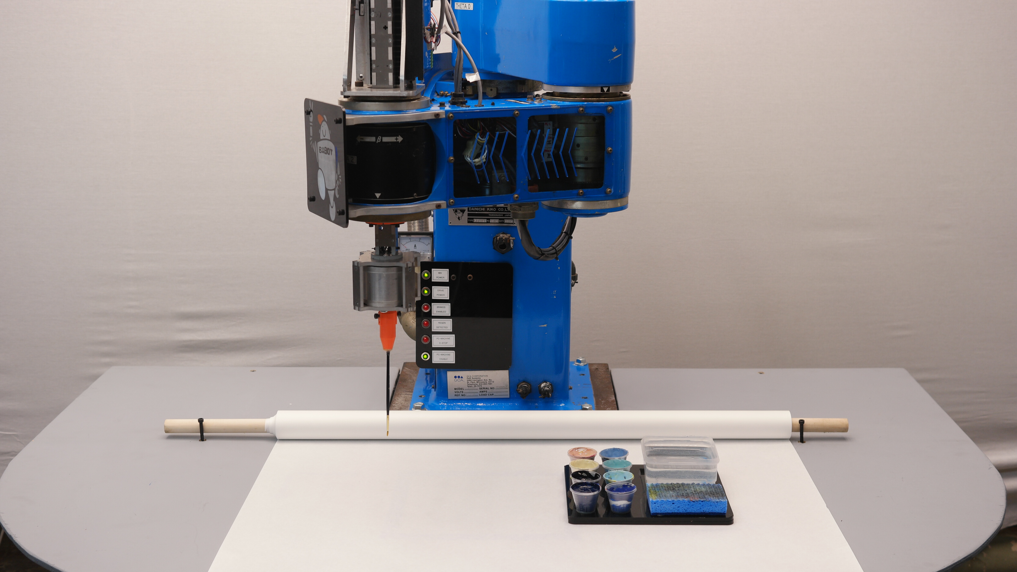
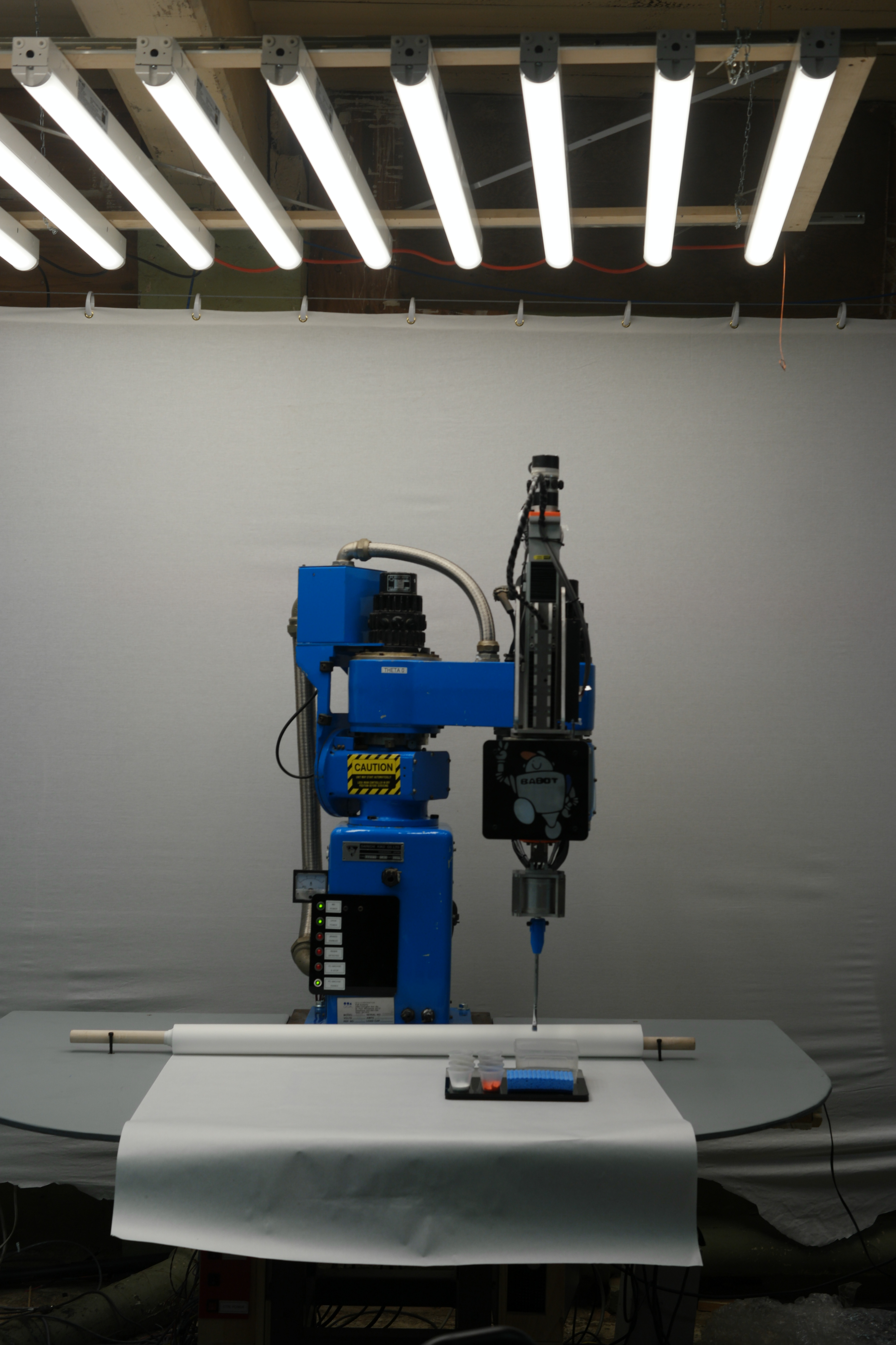
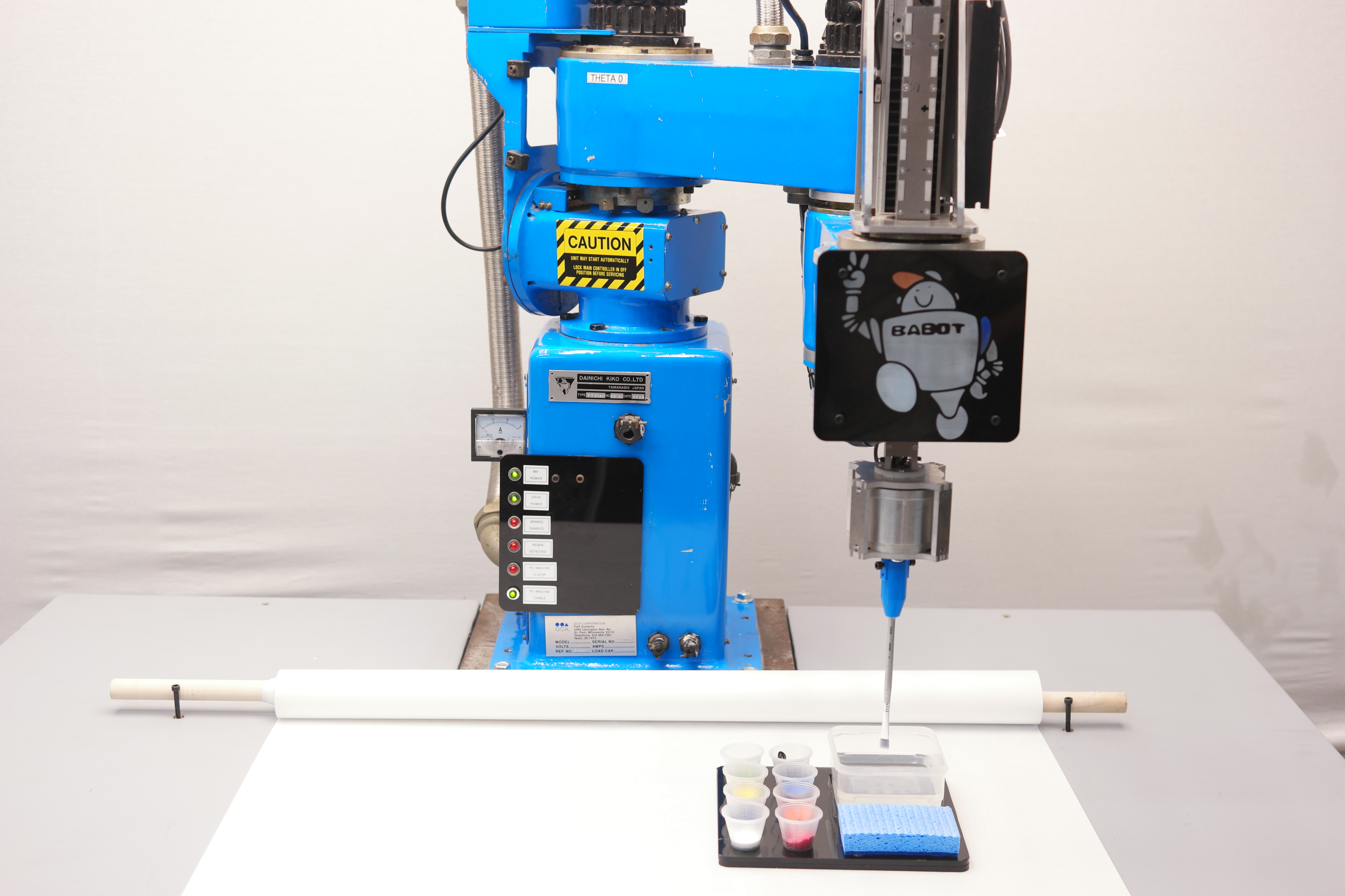
| This is an early test of the
fully-operational BLUEBOT painting with acrylics! Bluebot (BABOT) is an entry into the 2017 robotart.org painting competition. Babot started as a non-functional 80's robot, and over the course of 2 months, control electronics, servoloops and linuxcnc were meshed together to bring the machine to life. Everything from color selection, paint refill and brush cleaning are automated. There is a lot happening here behind the scenes, a kinematic model does the conversion for the polar based robot, all the encoder positions are fed back into the host computer for real-time feedback and position error correction. Waking up a large robot of your own? Follow along below for some SCIENCE Also
check out robotart.com & vote!
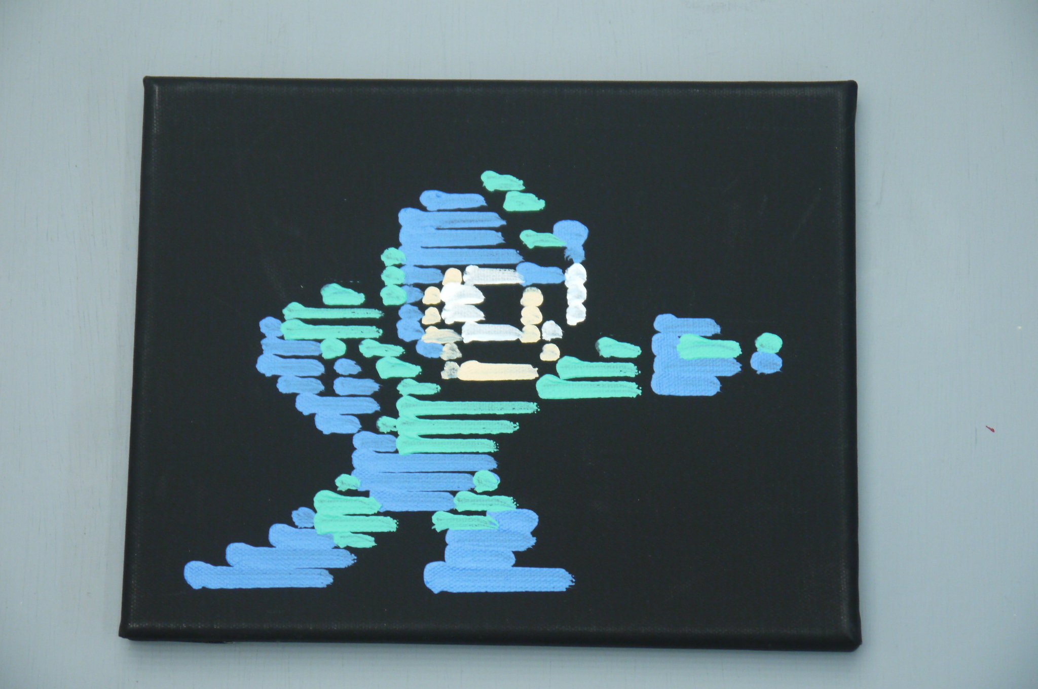
Paintings from team BABOT: [Megaman] [Sunset Mountainscape] [People In Space] [Circles & Lines] |
ACTUAL ROBOT GENERATED ART! Painted with Acrylics and a brush
 |
 |
 |
 |
A QUICK NOTE ABOUT
ROBOT ART robotart.org is having a competition click here, check out robotart & vote! <requires facebook login, I know I know> |
|
| Research Begins: Digging
into the archives to find out details about the bot |
||||||||||||||||||
 Starting with the
Internet, I went searching, aided by some awesome
comrades, for anything about this robot: Starting with the
Internet, I went searching, aided by some awesome
comrades, for anything about this robot:It has a curious history, sometime in the 1980s the company DAINICHI KIKO CO, (which became DAINICHI Machine and Engineering Co) partnered with PAR systems, for integrating their robots stateside. I called up PAR and found an engineer who was helpful in providing some history, and even a some information from a scaled drawing of the 'V' variant, alas, there were few details about this particular bot. I hunted further, I found another reference of a bluebot in use here [link]. I contacted Dr. Bicker and unfortunately any details about the robot had evaporated as well, but his team was successful in upgrading the robot. From an email: "I ripped out the existing controller and replaced it with a PMAC card, running under QNX". Progress, but I was hoping to get some details without having to determine them experimentally. If the theta-theta distance was something bizarre (350.211 mm), a number thats unfortunately difficult to measure, i'd rather get it from a manual. I found a mention of one of the bots on another blog [link] and contacted Dave, and unfortunately any data about the bots didnt come with his machine either, ok the hunt continues. Googling the name "Dainichi Kiko" does pull up this site [link], but after a phonecall to them, we found out that they were unrelated, jut shared the same name. Finally, I recently emailed the folks at dainichikikai.co.jp to see of they have any data, no response at all :/ |
||||||||||||||||||
 WHERE DOES ROBOT DATA LIVE? WHERE DOES ROBOT DATA LIVE?Books! as it turns out, a magical book titled "Specifications and applications of Industrial Robots In Japan 1984" has some details hidden inside about all of the Dainichi Kiko robot line. The magical libraries at MIT had a copy handy, I scanned, OCR copied and pdf-ifyied the 'Dainichi kiko' robots in the manual. This includes the following models: [Link to pdf copy] . Included robots are included in a table below so this is indexable for the next person awakening an old robot.
|
||||||||||||||||||
 OK
lets extract some useful intel: OK
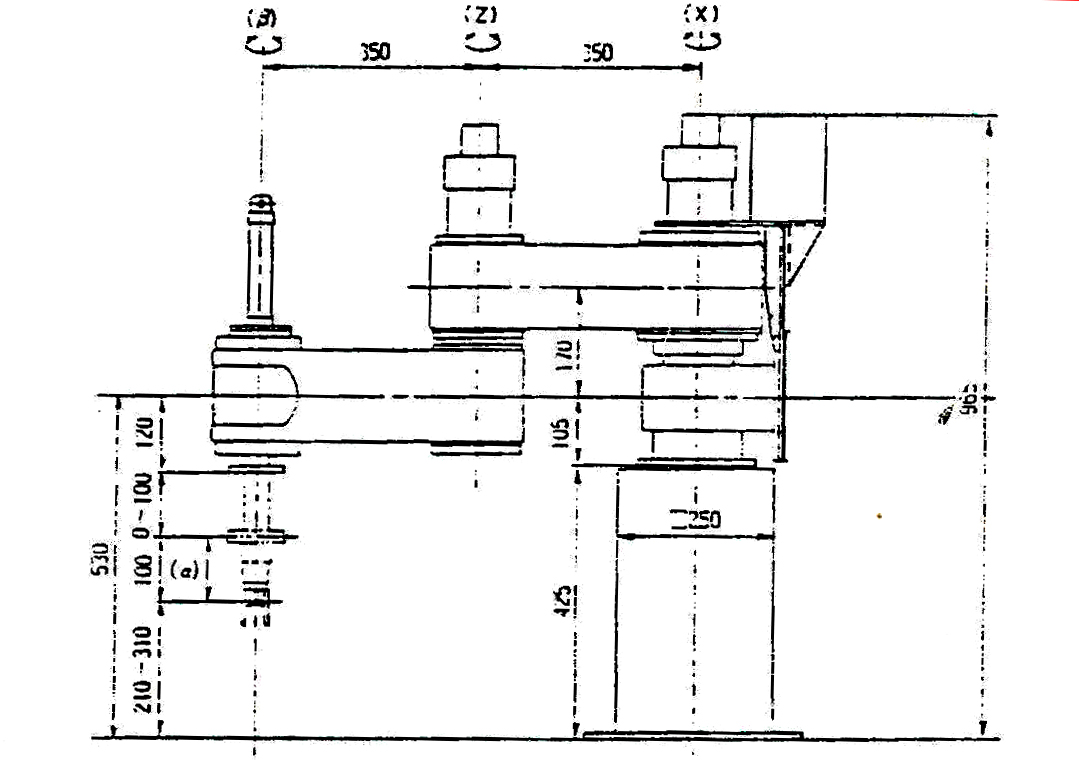
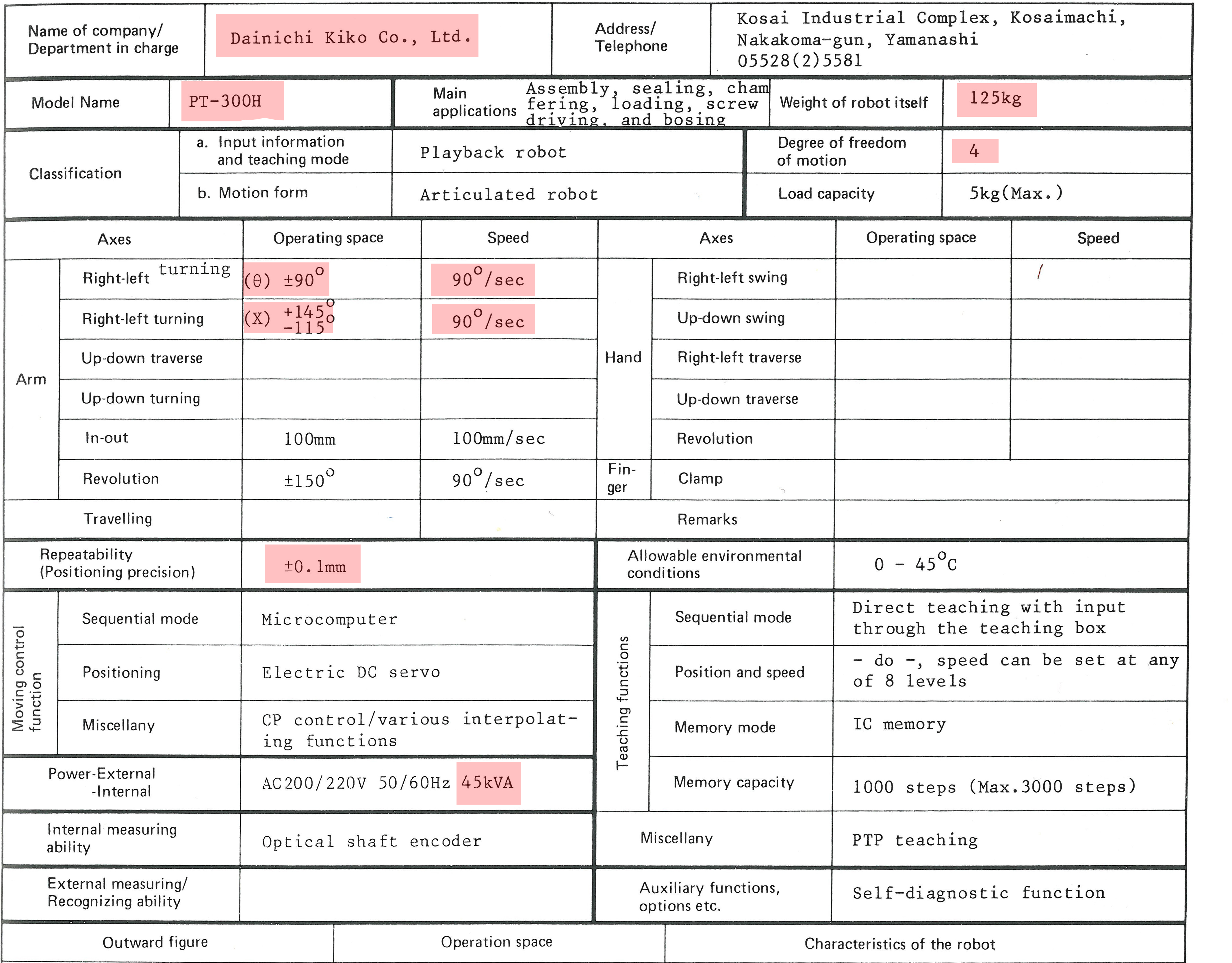
lets extract some useful intel:This scan appears to be 'bluebot', the theta-theta distance is 350mm, which should be 'about right'. Nominally this is all I was really after, assuming its accurate and not a 'rough dimensioned drawing' everything's quite good. Note this is the best I could do on a scan, the book used some very small font. The robot itself is a PT-300H. Initially i thought the '300' would be the theta-theta dimension, but looking through each of the robot versions, I have no idea what the PT/PV ### version numbers are accounting for. |
||||||||||||||||||
 Here's
the data: Here's
the data:The interesting bits are quite good, and highlighted. 0.1mm resolution (3.9 thou) at full extension is pretty darn fantastic. Some of the other data is a bit curious. 45kVA? Unless the controller for the robot was also a room heater, or incredibly inefficient, the power consumption is probably closer to 4.5kva (assuming ancient linear drives and a power hungry computer). Finally, as I had mentioned, its a heavy robot: 275lbs (125kg). |
||||||||||||||||||
 The
top-view diagram The
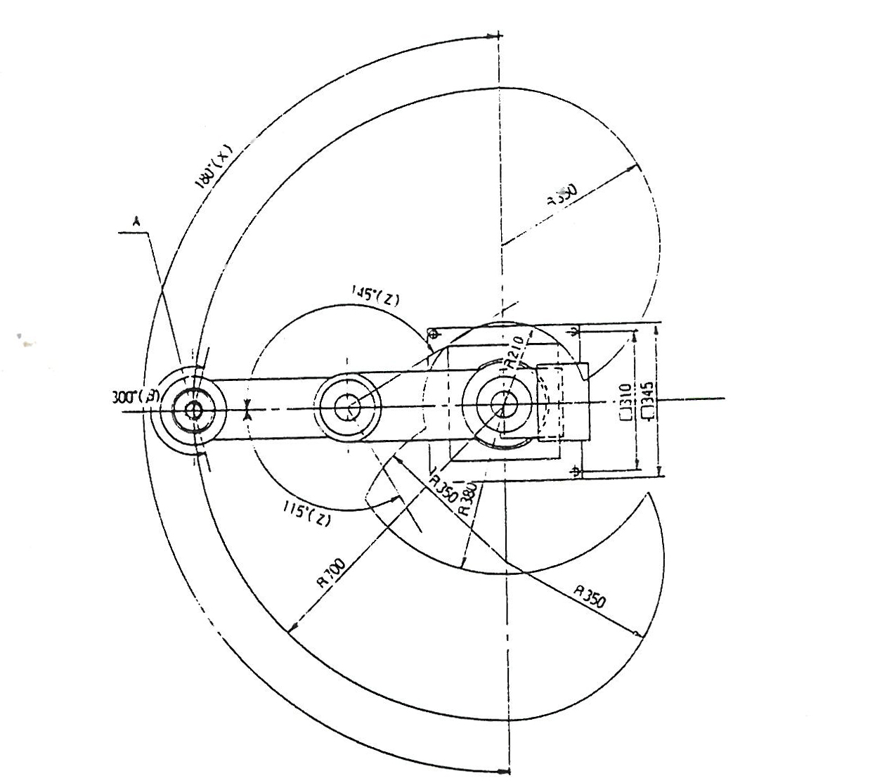
top-view diagram This does indicate that the robot has full range on its theta 0 axis to allow for a proper 180 degree outer circle. From this diagram, we can make a rough 'valid positions' map, which feeds linux cnc areas where the robot position are acceptable and areas where the robot would collide with itself. This drawing itself is fairly excellent, it helped define the table space as well as how far away any robot related hardware should live. |
 |
| Robot gets a new 'life' and some new Mechanicals | ||
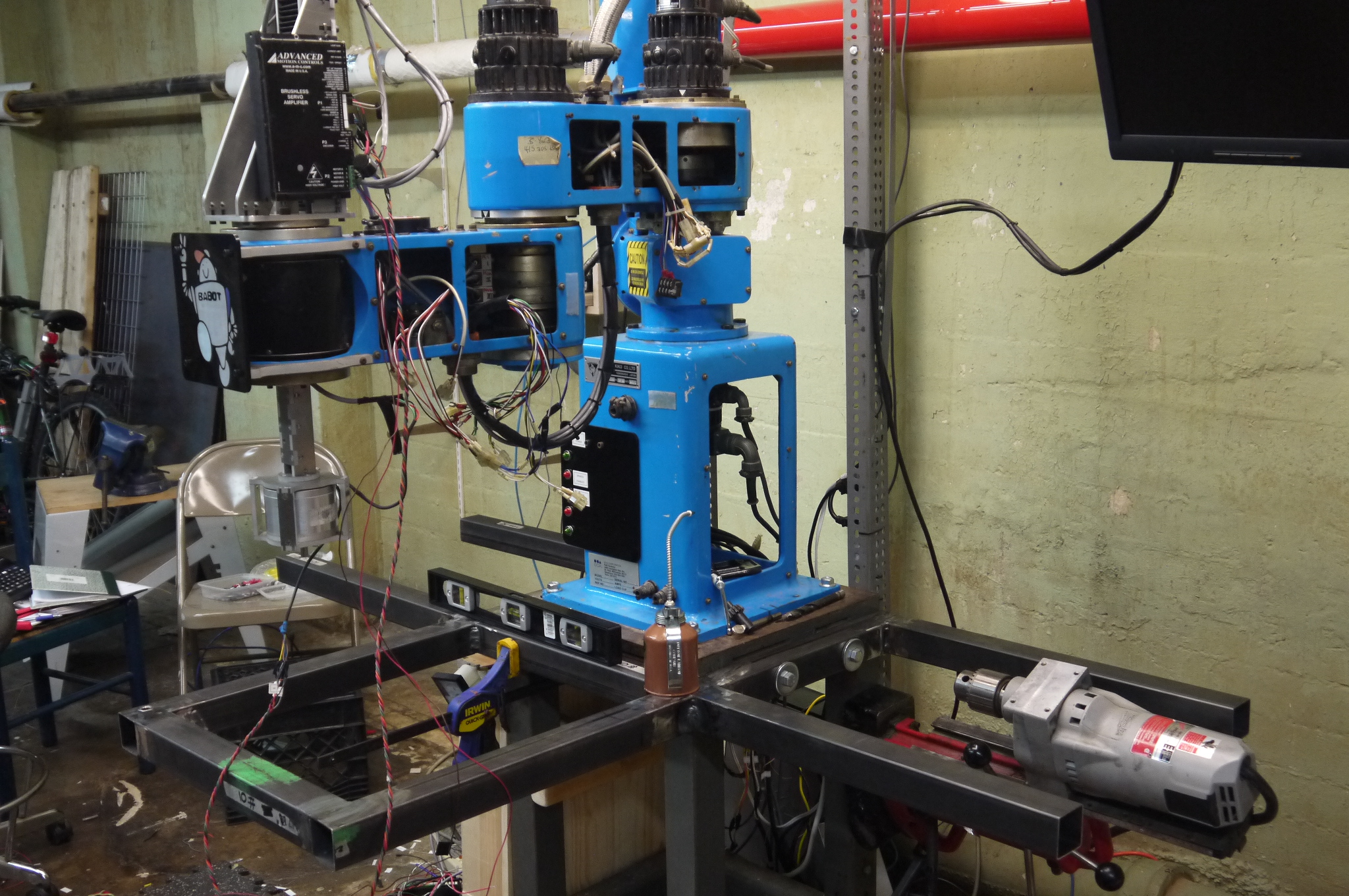
| I lucked out and inherited a beautiful big robot. Unfortunately I didnt grab a photo of it in the basement where it had been living. It took a bit of heaving and shimmying, but eventually it ended up in the mighty Rob's pickup. It then found its way into a wondrous basement workshop. The robot itself broke down into two parts, its base, which nominally protected the theta 0 motor and provided a surface to work from, and the remainder of the robot. Shown in the photo is a base that the robot sat on, made of, what i can only describe as, mega-steel. | 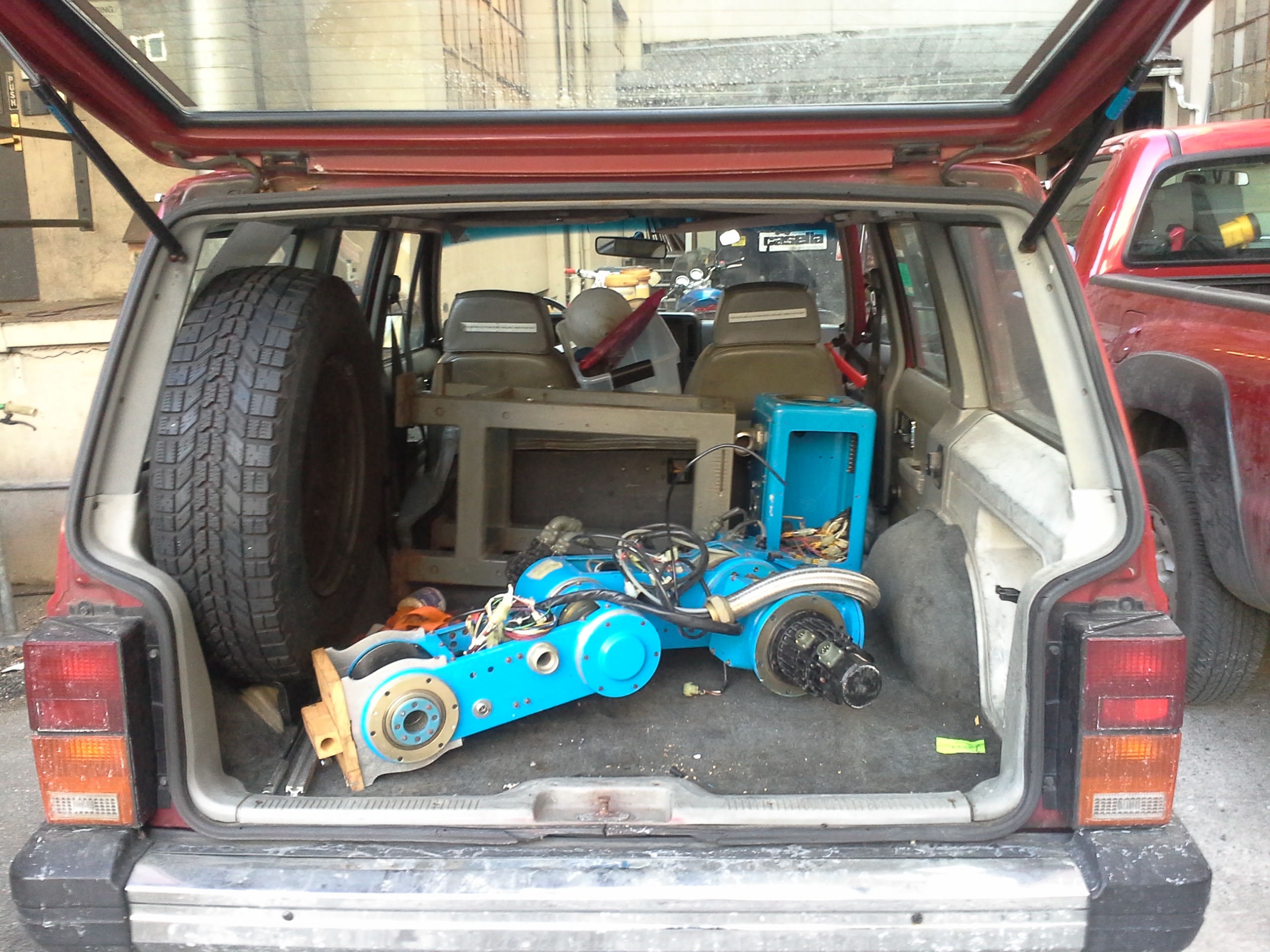 |
 |
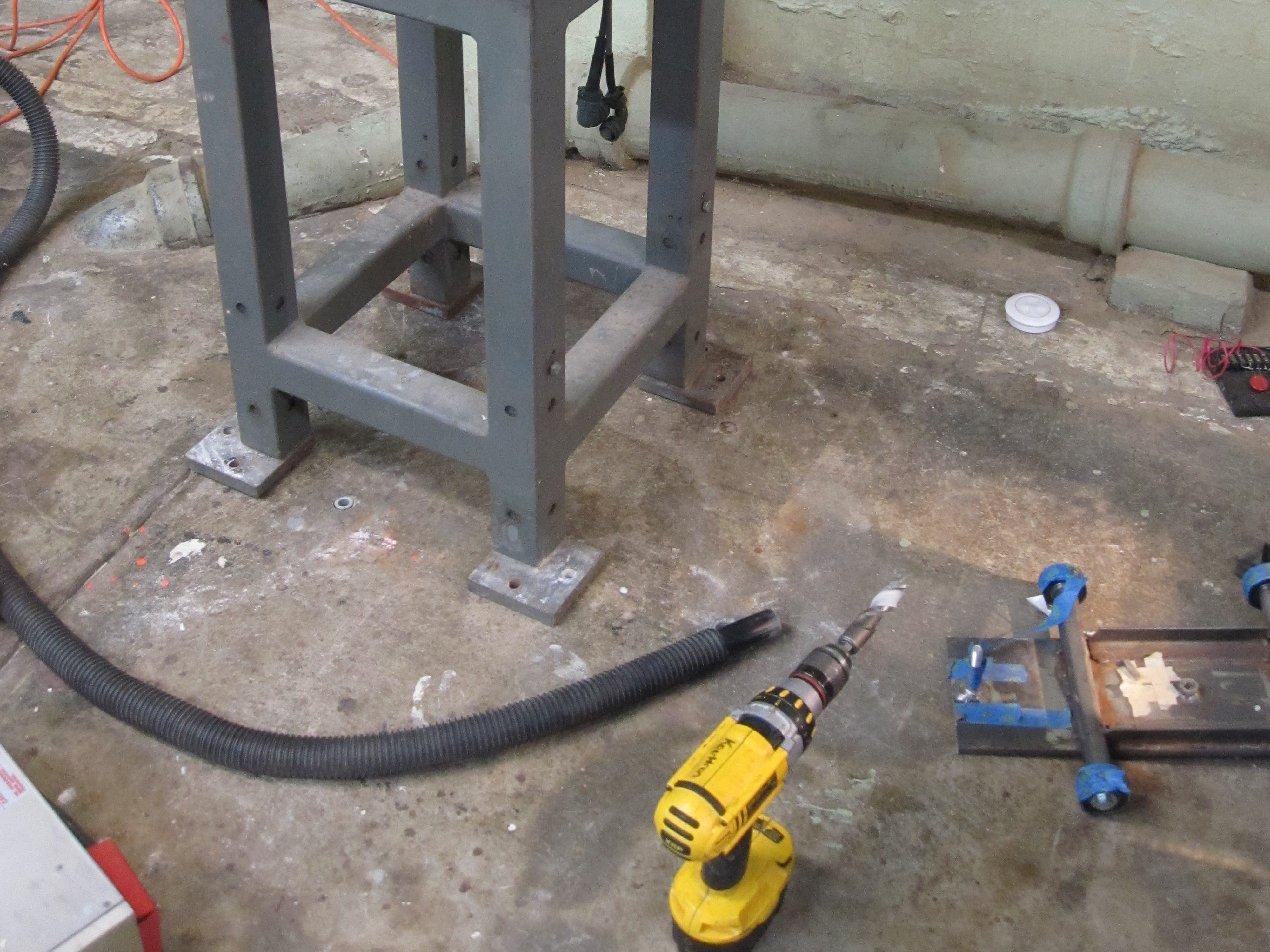
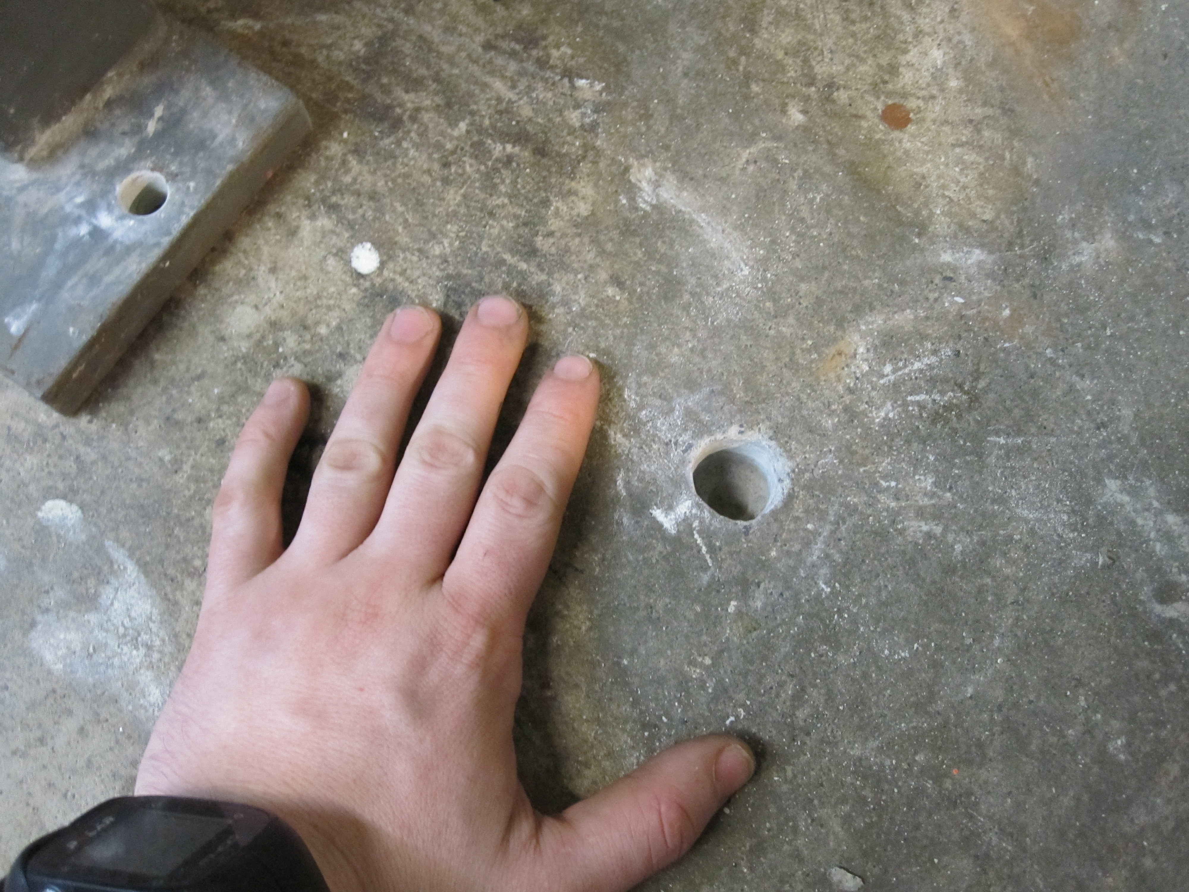
| Mega
steel base meets a concrete floor A concrete bit and a non-hammer drill made quick work of chewing into the floor, a shopvac was placed right next to the hole during the drilling. A 1/2" diameter hole was drilled first (to limit the loading on the final bit) and finished with a 7/8" diameter bit. This took about 10 minutes per hole, but, admittedly it was overloading the drill. I waited 10 minutes between hole to let the drill cool down. Shopvac and a respirator was used, along with safety glasses as appropriate PPE. |
 |
 |
| Aaaaand
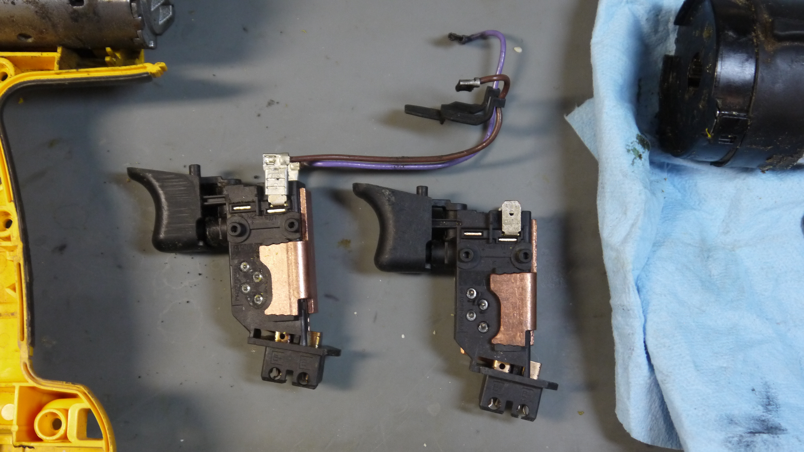
the drill cooked After the third hole, the trigger controller for the dewalt failed 'full on hbridge short', any battery connected pumped ~40A into the handle and smoke would pour out quite effectively. This was a heavily used drill, it had been emitting the 'sad motor' scent for a while before the drilling. |
 |
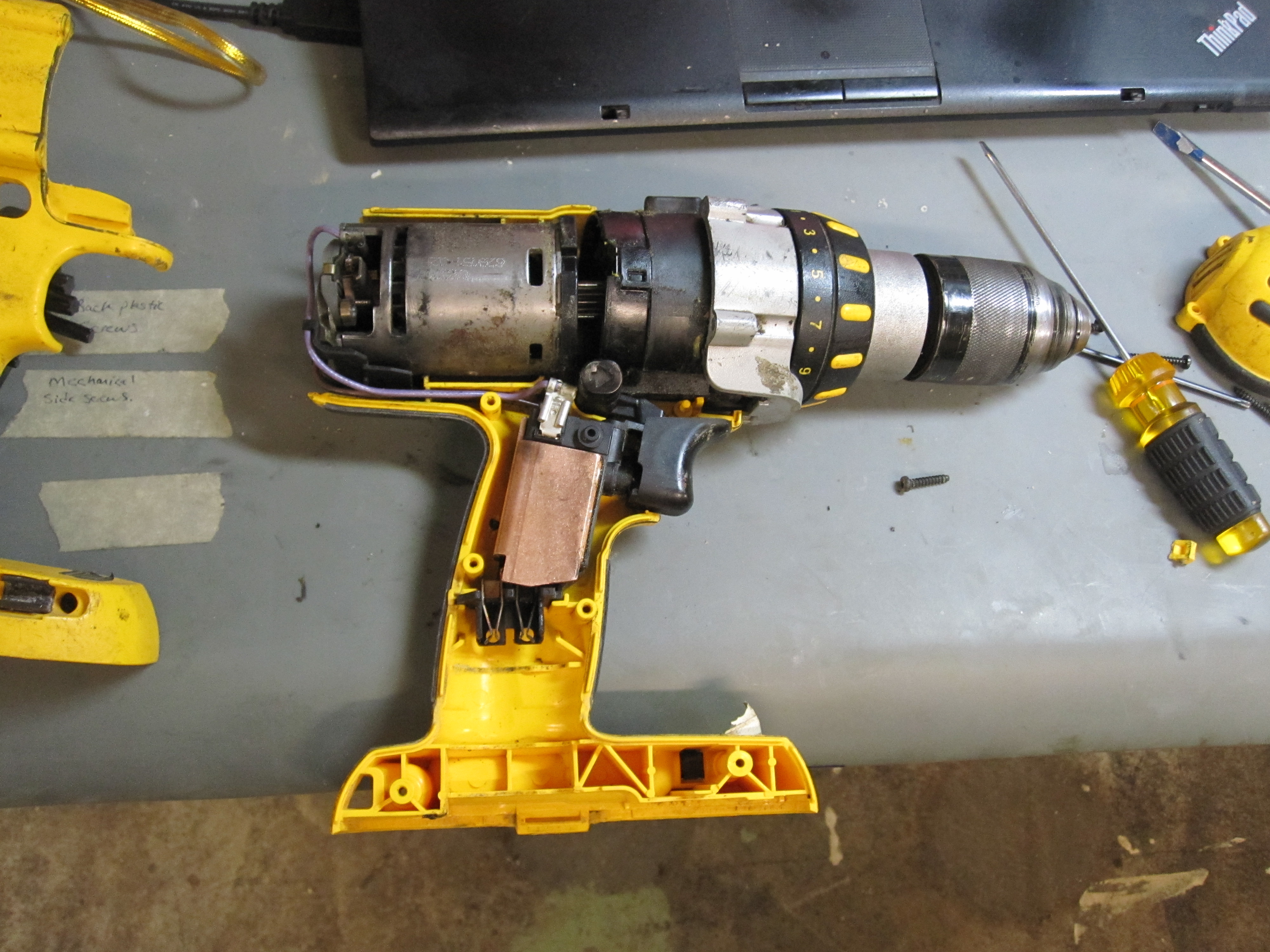 |
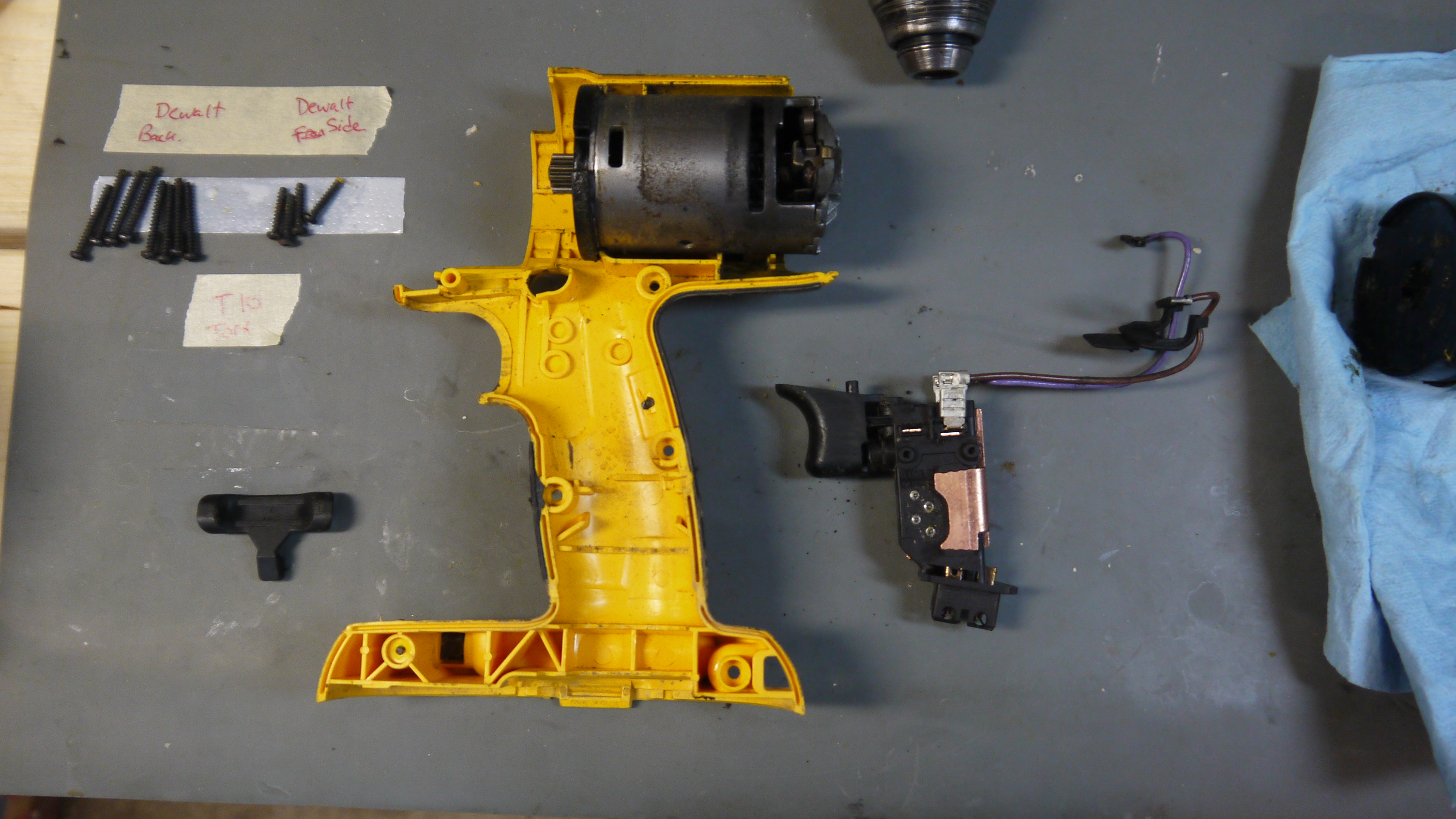
| A quick
drill-repair later... Admittedly, the drill [Dewalt 9180] was used and had seen a proper beating. I grabbed a replacement drill trigger and a replacement motor. Some disassembly later and the drill was back up and running. Its a nice drill, and fortunately with the advent of new 20v form factor drills, these have all become quite cheaper. For more details on the drill repair, see here [link]. |
 |
 |
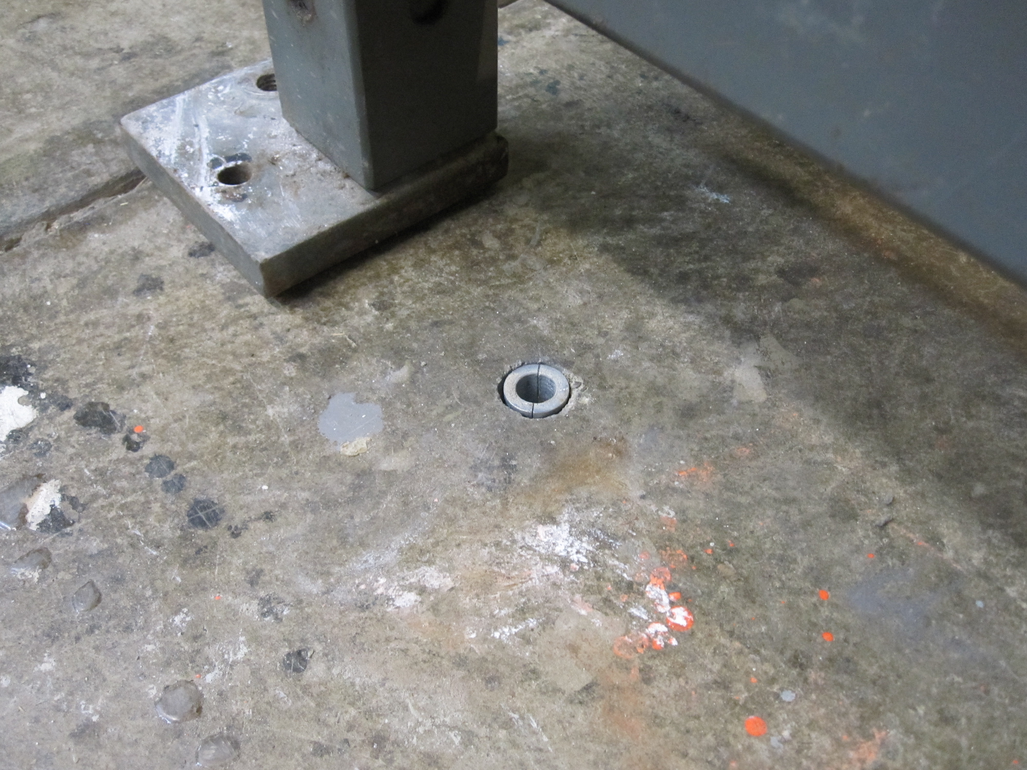
| The robot stands up: I cant harp on this hard enough, if you want to get whatever your robot / contraption up and running, especially with reasonable acceleration and deceleration, a proper mating to the environment is a must. For this application, I used 'giant frigging concrete anchors'. Structural mating to the environment was an issue on a previous robot [link], and as ideally this would move quicker, there was plenty to do. Specifically I used 7/8" diameter concrete anchors [link] that attach to a 1/2-13 threaded stud [link]. Nuts and giant washers were used as leveling hardware. To drill into the concrete i used a combination of masonry drill bits ending up with a 7/8" diameter hole. To 'lock' the expansion anchor in place, a threaded bolt is used and a nut is tensioned against the expansion anchor, this jams a moving slide into the anchor and helps keep everything pre-loaded. Note the expansion bolts are rated to 8100lbs shear and 5100lbs pullout when used correctly, Oversizing really wasnt harmful in this application. |
 |
 |
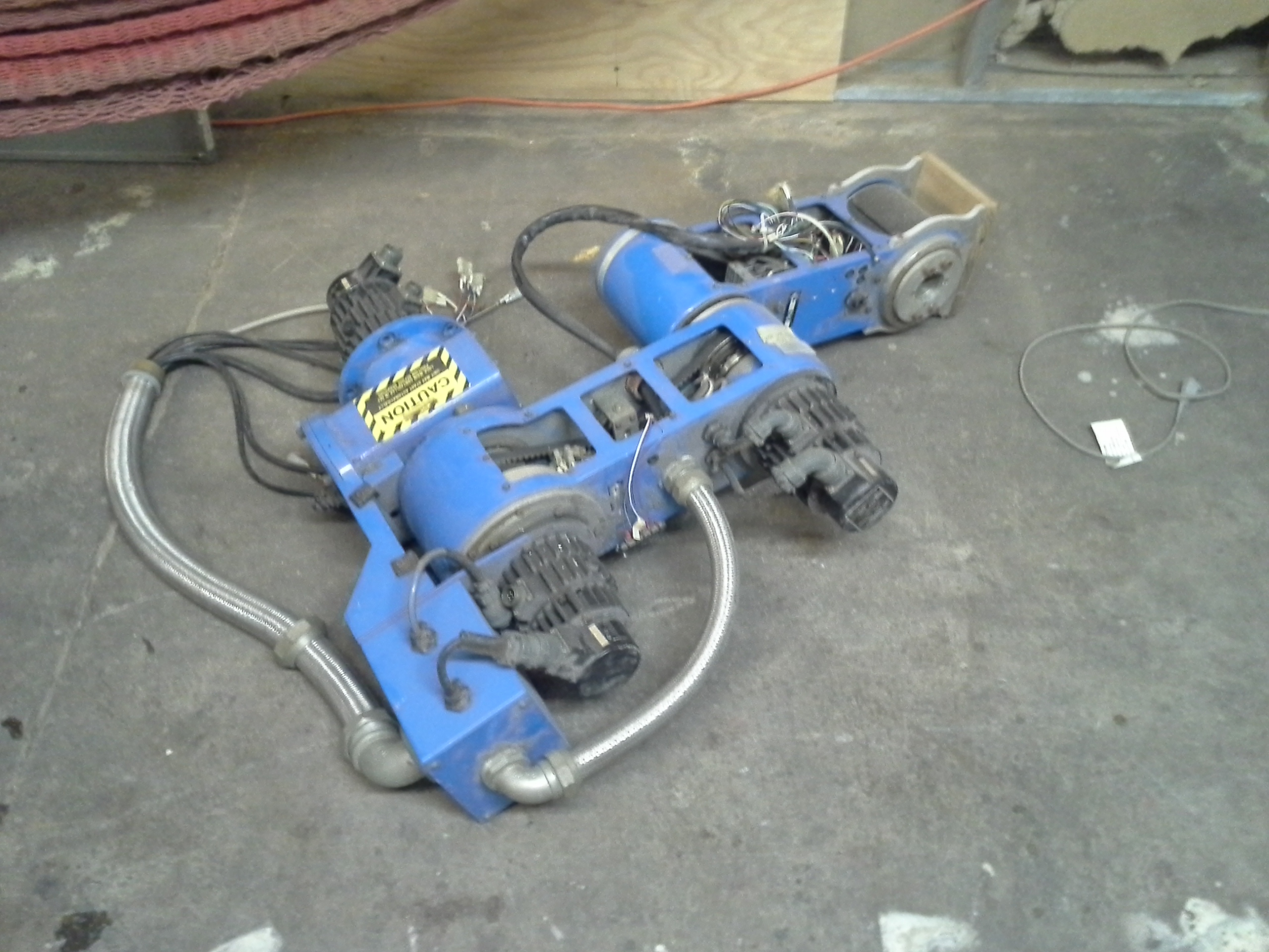
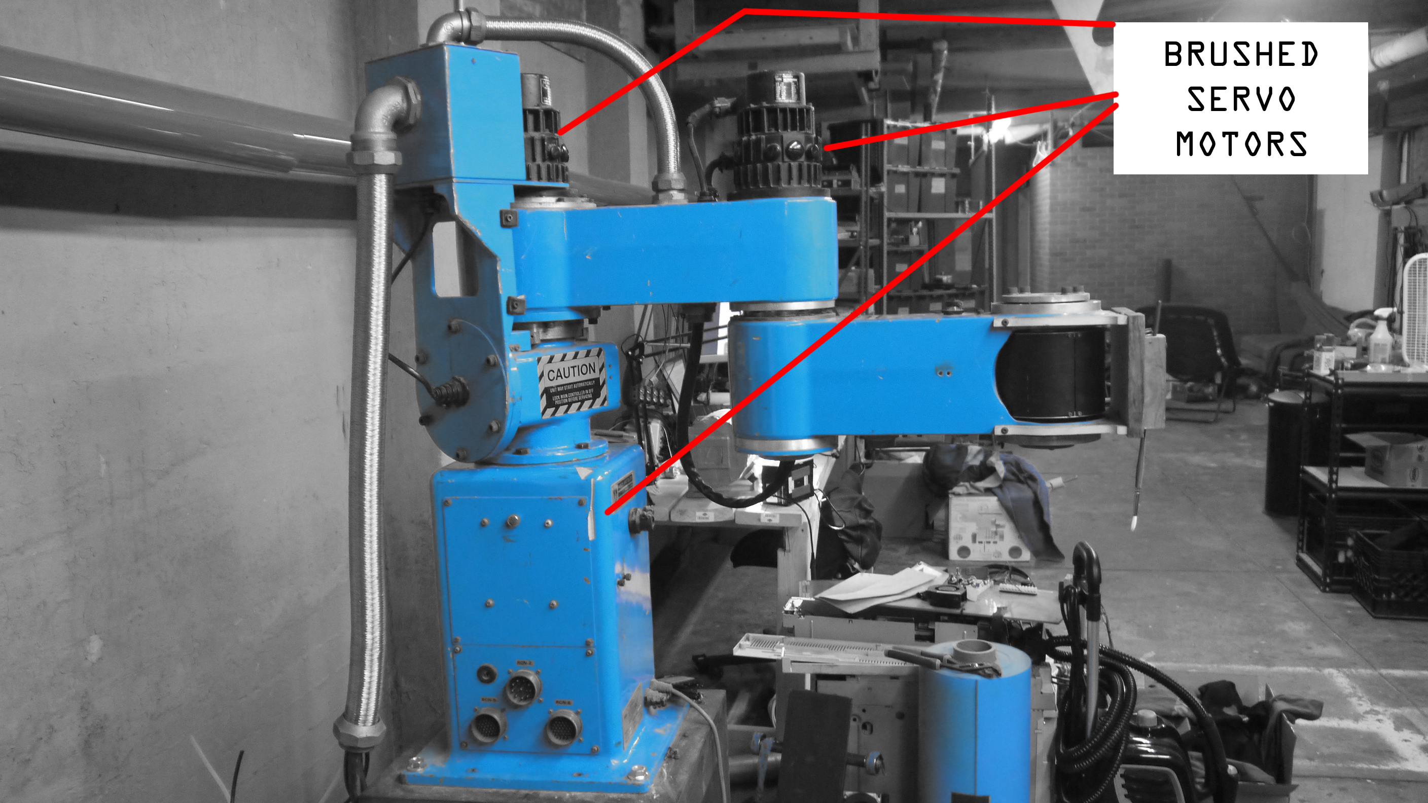
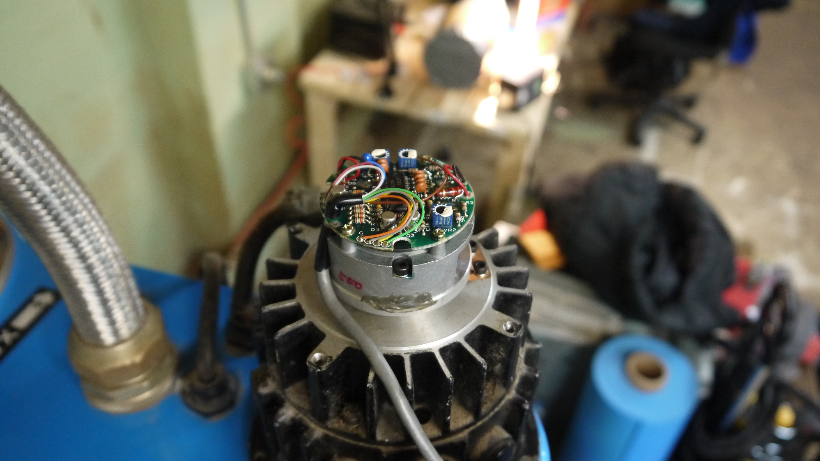
| Discovery: What motor topology is used? I was fortunate enough that the motors on at least two of the axes were out in the open. They had four brush caps, so that quickly indicated it was most likely brush-dc. This was great news, as, they werent some bizarre 5 phase magic or just, giant-mega-steppers. On the opposing side of each motor is a 500 count / revolution encoder. |
 |
 |
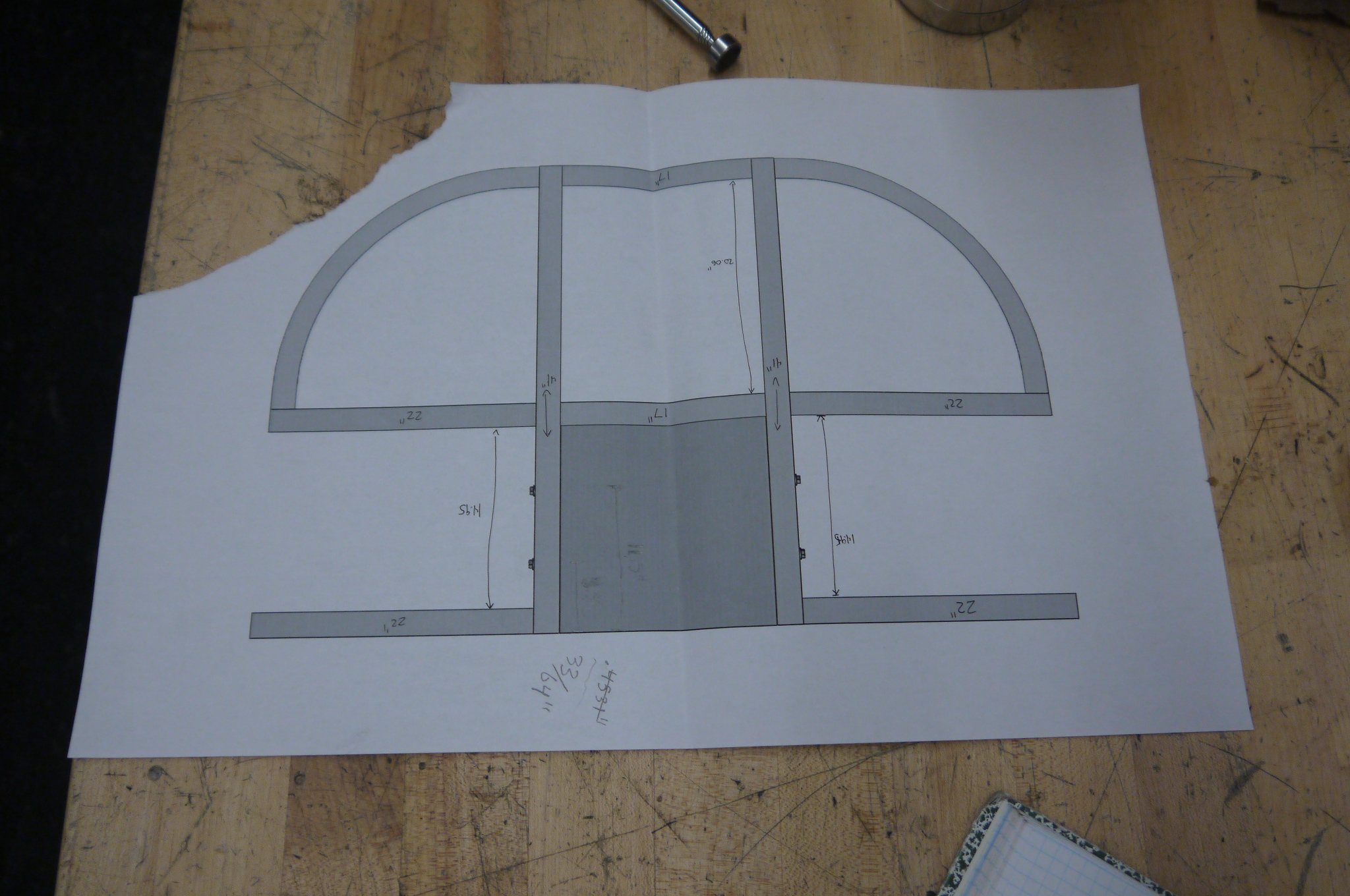
| Now to give it a surface to work on! Steel for the table was ordered from speedymetals, everything came out quite excellent, I initially plotted for a table with a swooping bent curves along the front sides to mimic the scara maximum usable area, but alas, bending big tubing was not really as easy as I had plotted. |
 |
 |
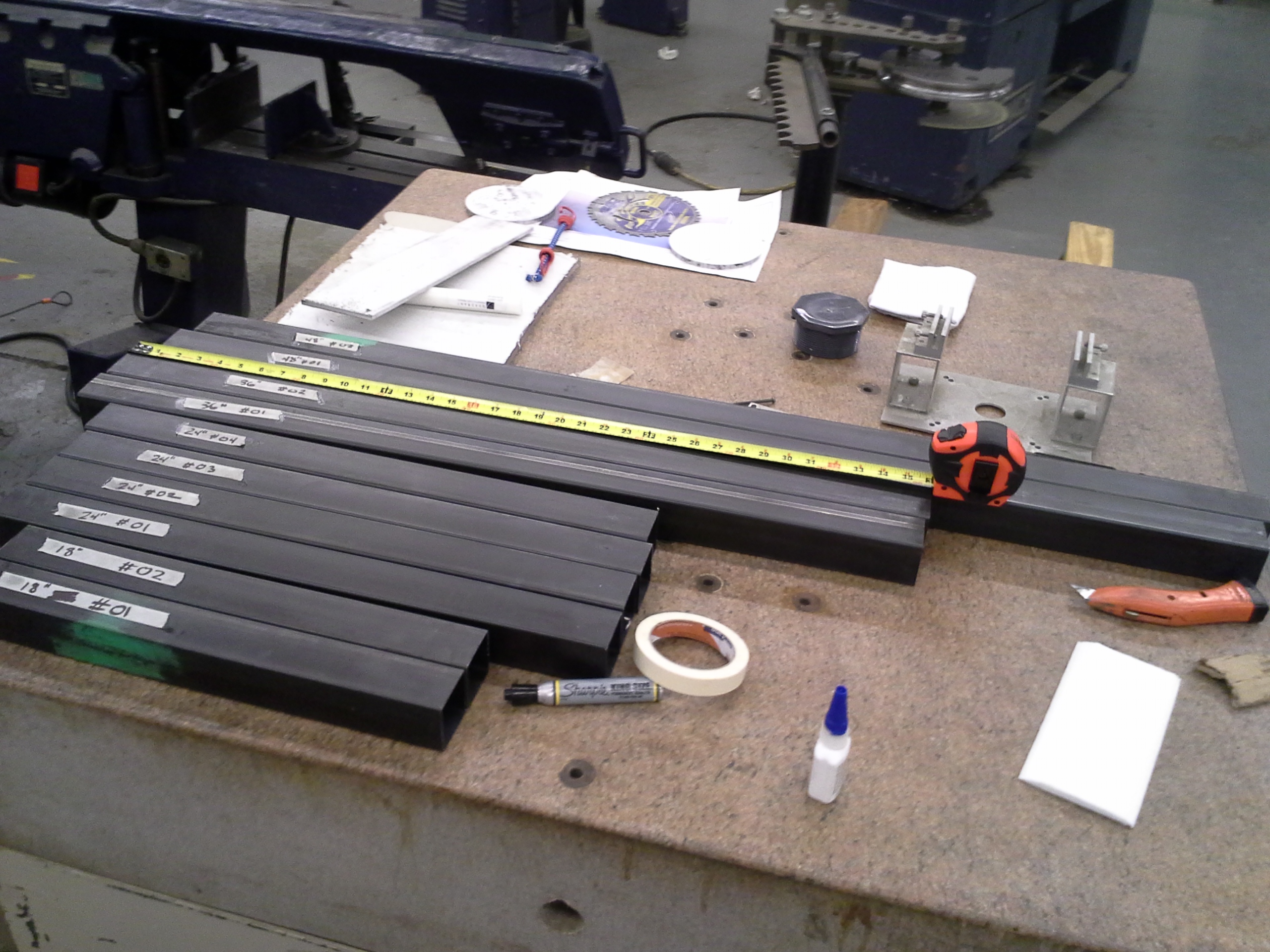
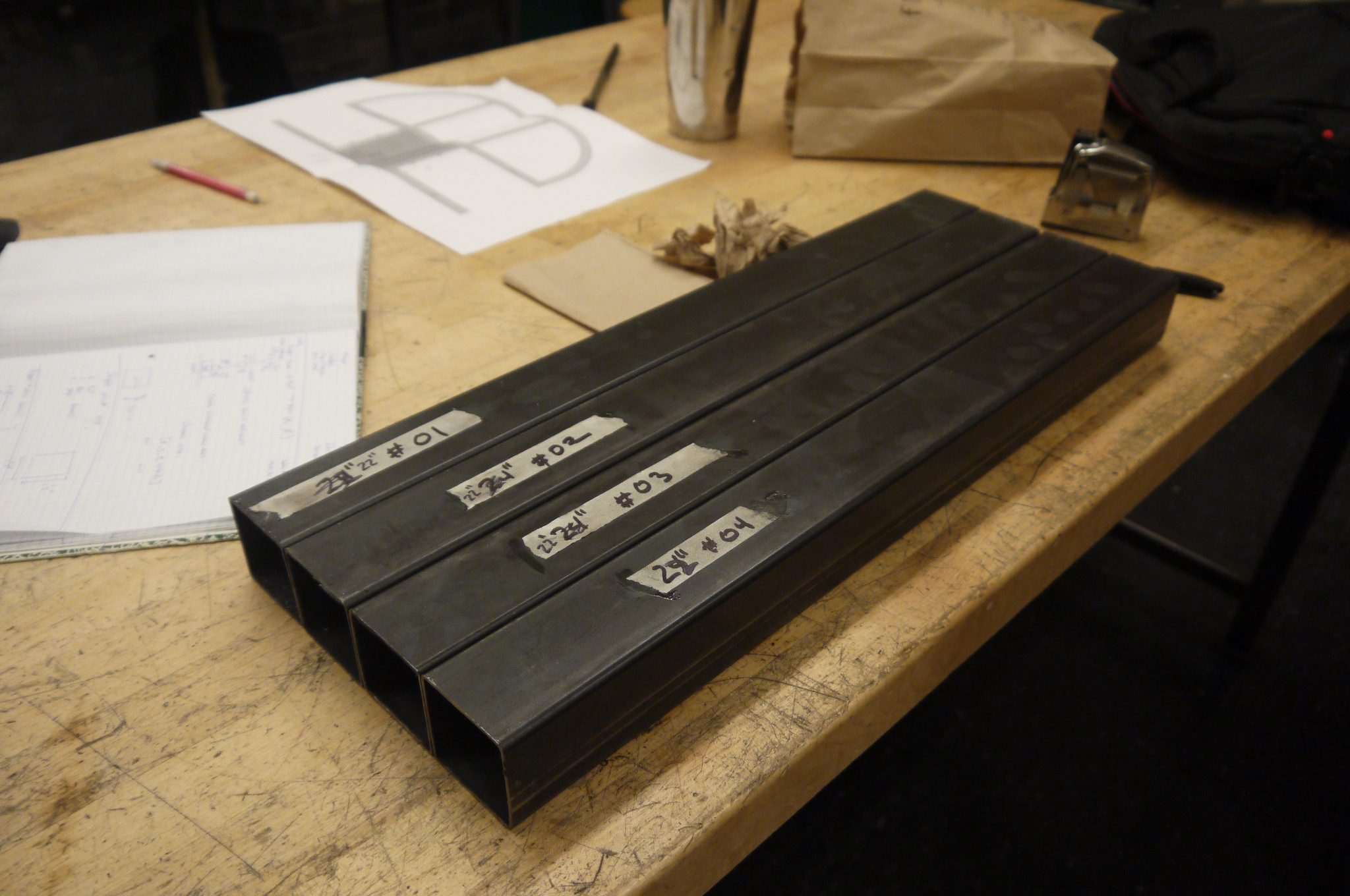
| A 'big ol kalamazoo' bandsaw was ued to cut everything to length, I was surprised how 'good' the steel tubing was, everything was accurate to +/- 1/8 of an inch or better when it arrived. Finally i labeled everything and started to prep for welding. | 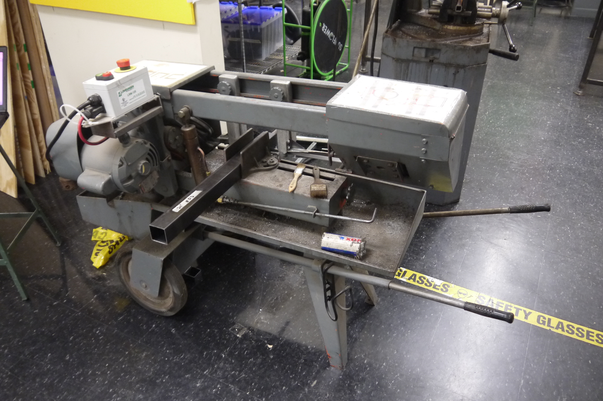 |
 |
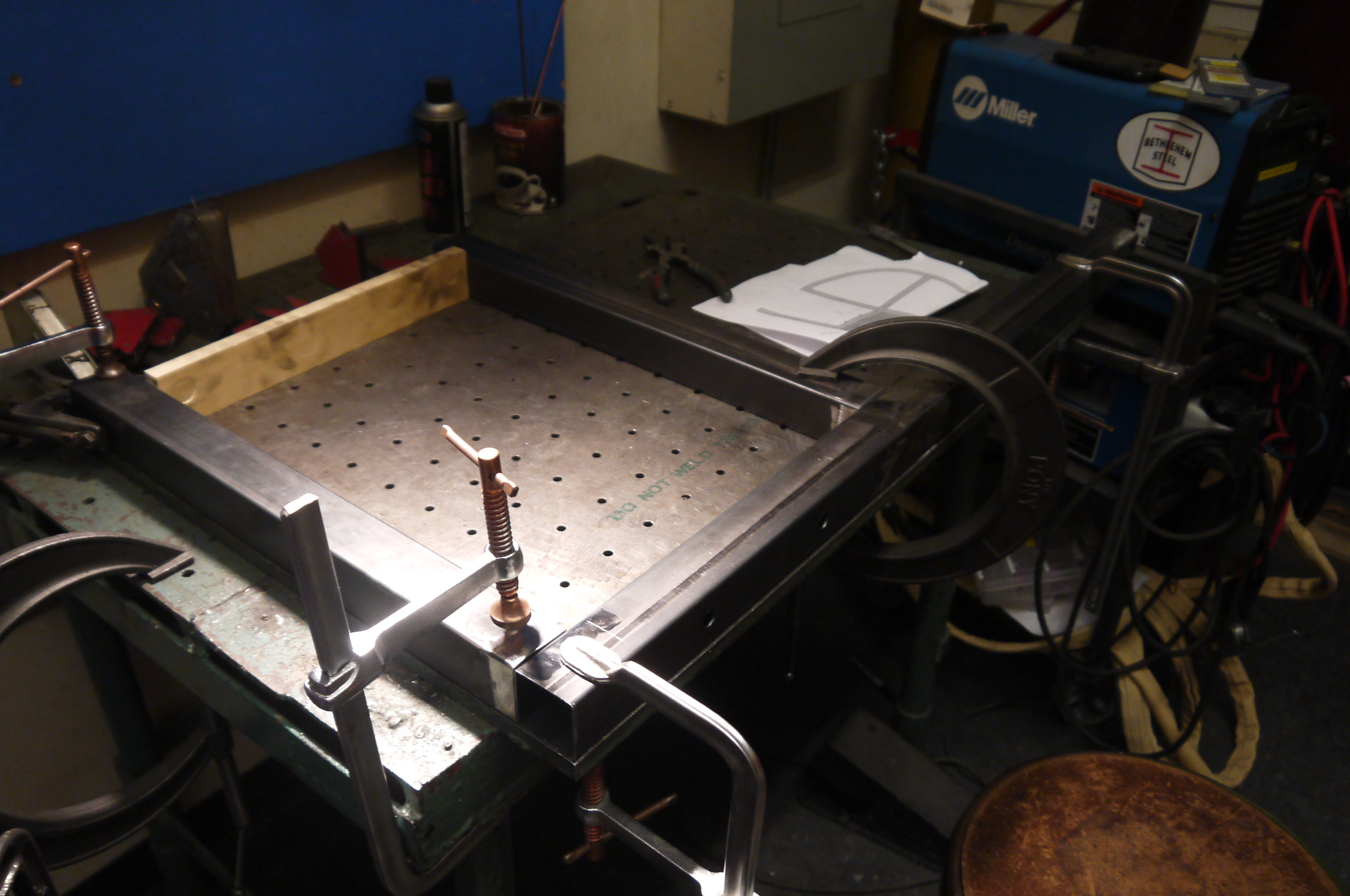
| The mighty birkel flappy-disc'd all the mating surfaces and we started setting up for some quick mig welding, but alas, the welder was out of spool. I went to town with a tig torch and slowly filled in the gaps and melted material together. It took a while, but came out great. | 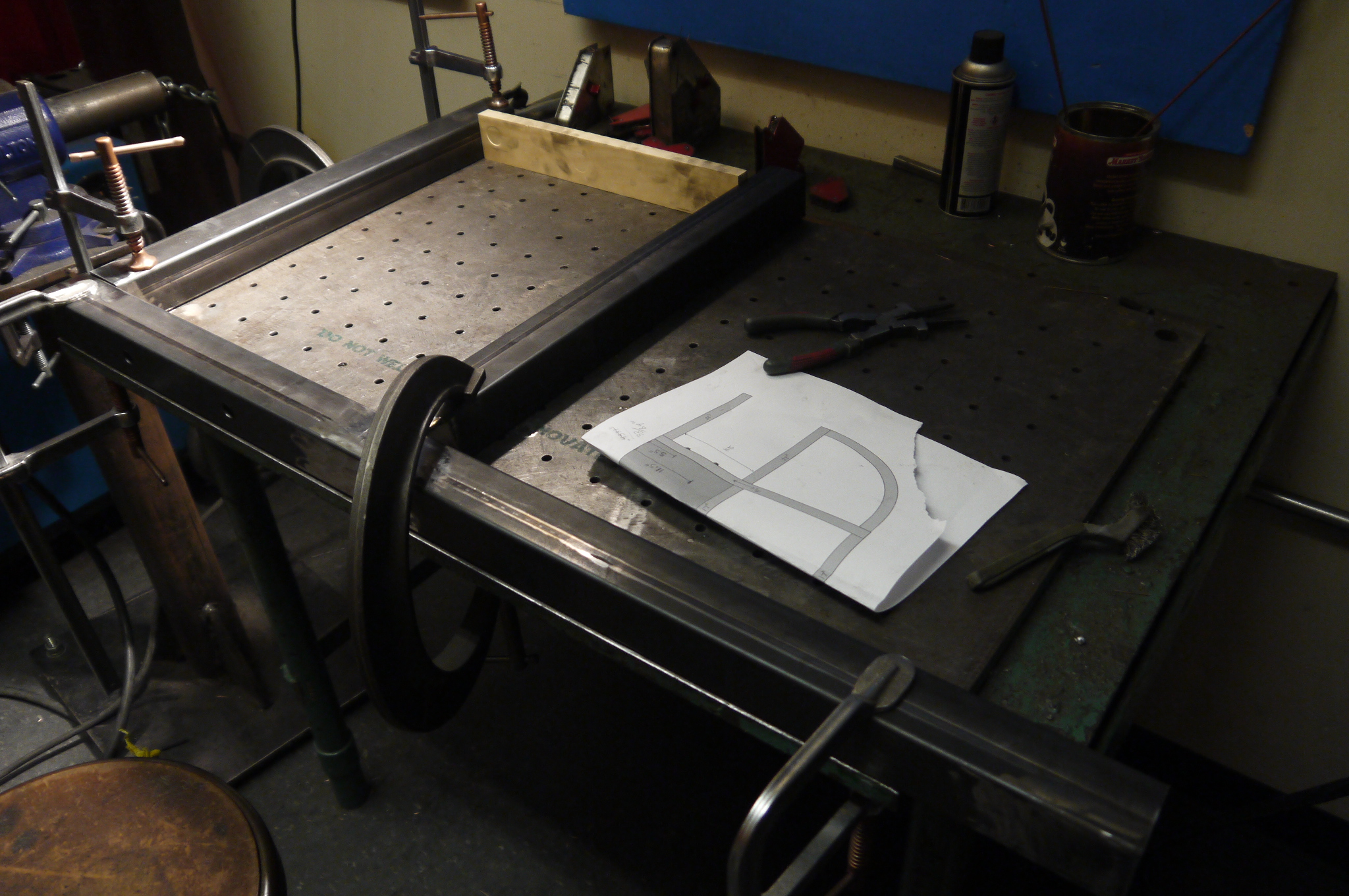 |
 |
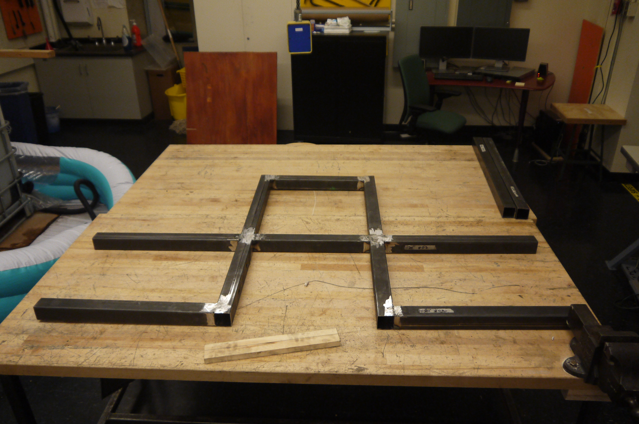
| Some back and forth checks later, and lo, a flat, flappy-disc scaned table base that 'should' snugly fit up against the robot table. | |
 |
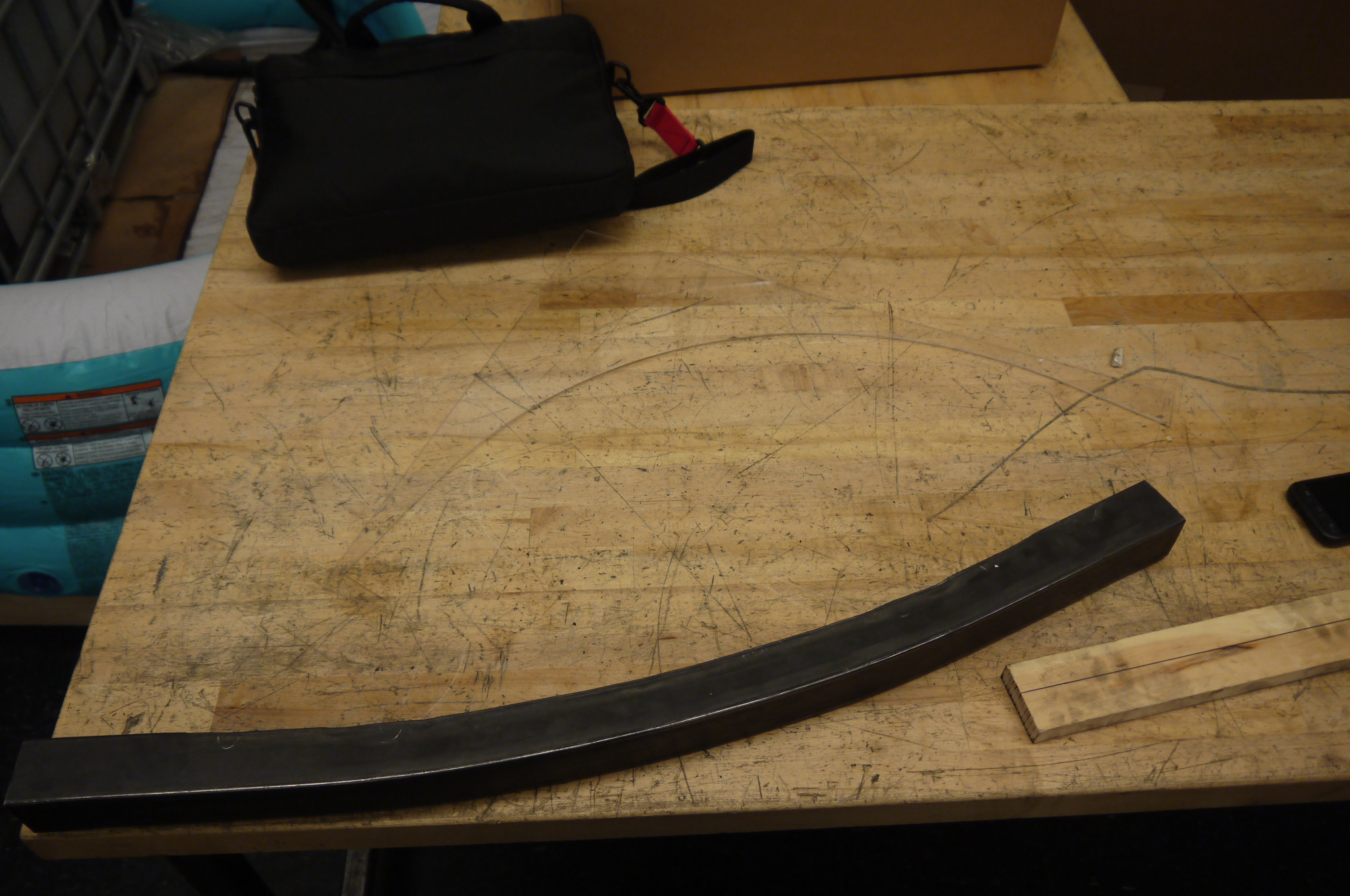
| Attempting
to
bend 2" diameter steel tube. The magical Jack had this wonderful contraption, which even had a 2" diameter square tube die. Its from SWAG offload [link], and uses a harborfreight pipe thread cutter as the drive mechanism and rolls the tube between two mondo rollers. From what i can tell, the 2" square die may have been for some kinda soft aluminum alloy, as myself and birkel really had to go at it to get the amount of bend shown (far right). I ended up opting to not go with the extra front supports and roll with it as it is. |
 |
 |
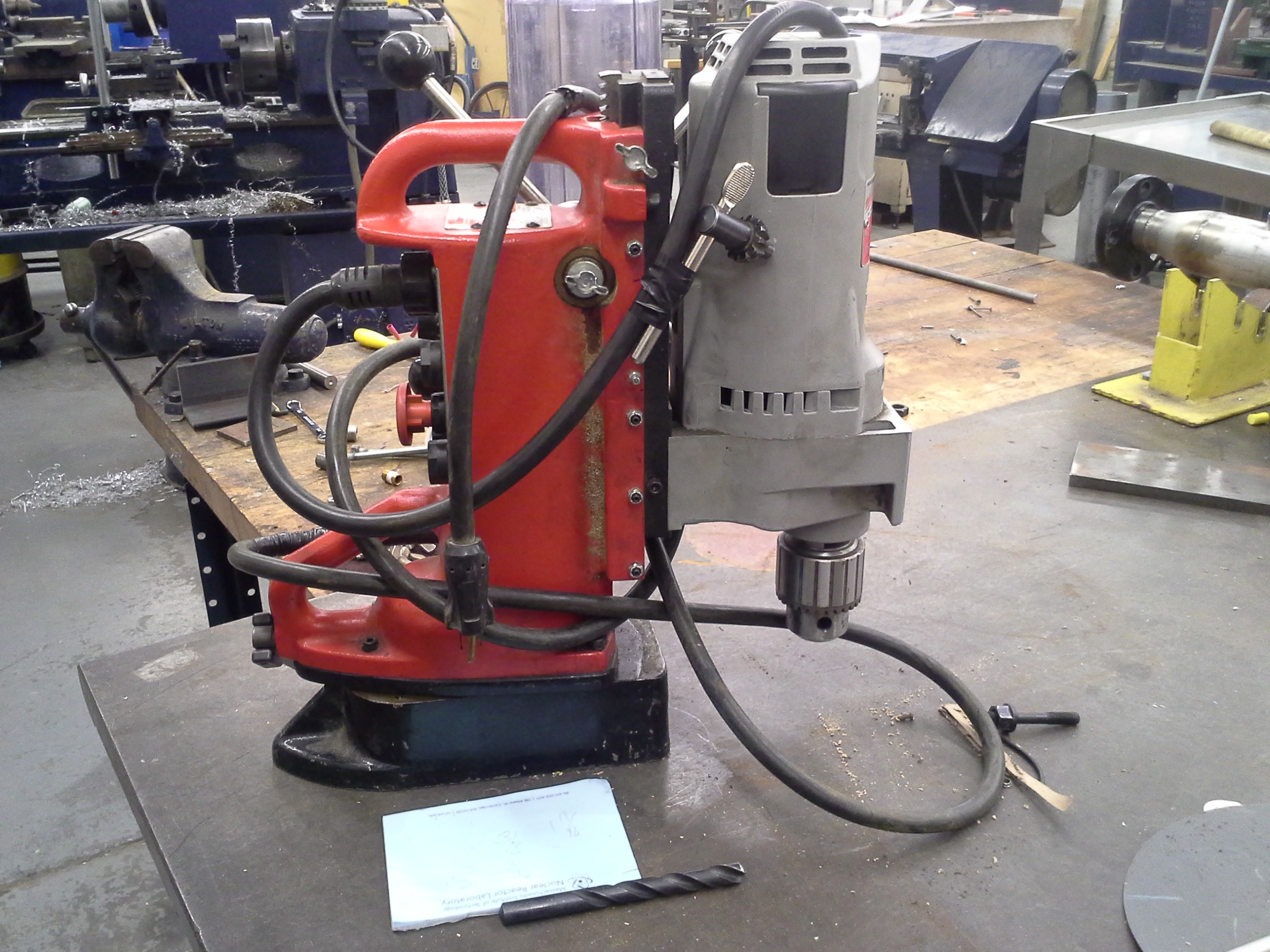
| BUT HOW
WILL YOU INSTALL SUCH A MEGA-TABLE DANE? BEHOLD
MEGADRILL Megadrill is an electromagnetic base perpendicular drill assembly, you hold it near where you want to drill, hit the electromagnet, then adjust the final position and lock in with a clamp. This was used to bore the 1/2-13 bolts that held the table in place. Looking back this was such an excellent way to get the table mounted after it was clamped in place, the drill did the 'perpendicular' thing quite well. |
 |
 |
| After everything was drilled and cleaned up, the table was clamped in place, tapped to level, and then tightened down with grade 7 1/2-13 bolts and some mega-washers to distribute the load. The table was now a part of the frame and rigidly a part of the bot. |  |
 |
| Seriously this thing is awesome, probably great for boring holes into steel safes, albiet slowly. All four holes were drilled through the frame and table in under an hour, worked out quite well. | 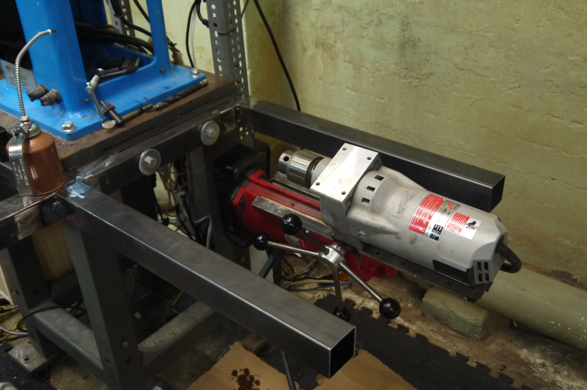 |
 |
| A quick video of using
this monstrosity to bore into the table. Can i mention again how excellent this contraption is? The mighty birkel aided in this quest. Shown far right is the table supporting him. |
 |
|
| The table was drawn out and traced with a pencil. A dewalt portable circular saw was used for the square cutoffs and the edges were cut out with a jigsaw and trimmed to fit. I opted for a large continuous sheet of 'nice' grade plywood, as this would probably remain the work surface throughout the early use of the robot. After verifying a decent fit, i removed it from the robot base, sanded it with a ryobi vibrating sander, cleaned up the edges and prepped for paint | 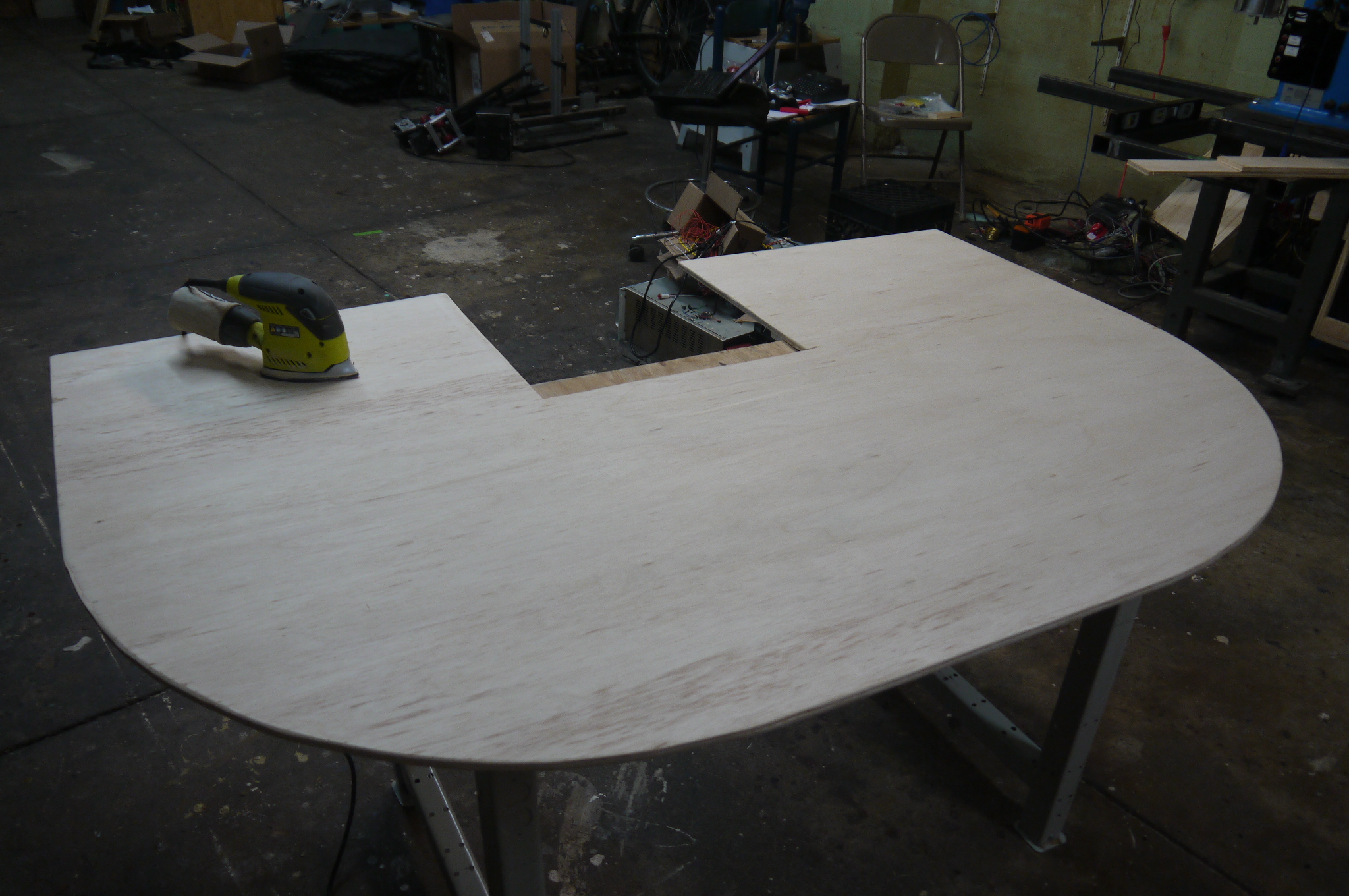 |
 |
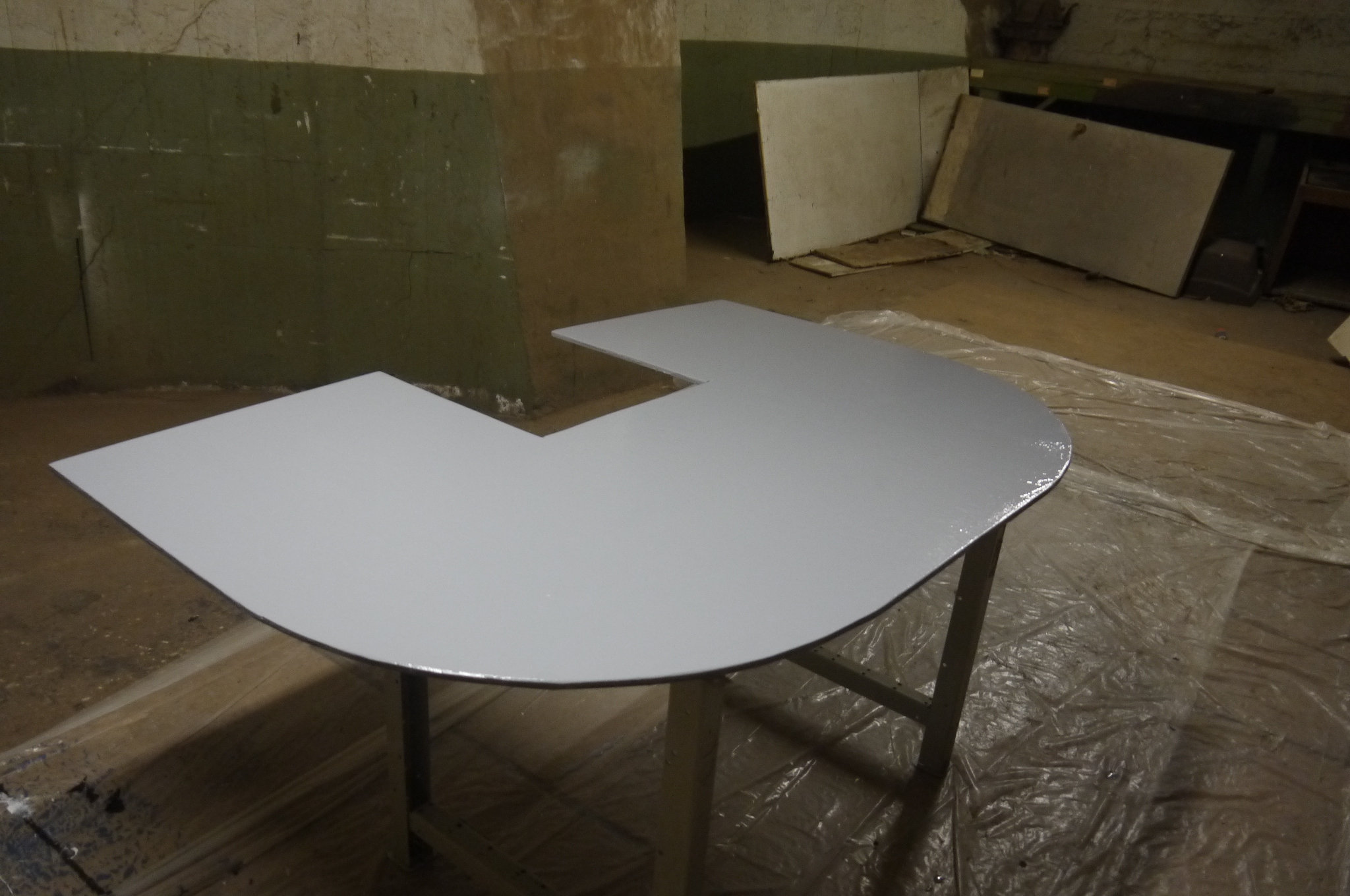
| For a table surface, I didnt want to go for straight white (easy to spot dirt), and I didnt have 'gray' paint handy. Thanks to the ever excellent Sam, gray is actually just a mix of white and black. Somehow i'm building an art robot and I missed this. After some careful mixing of white and black, grey was born and rolled on using an 8" roller. I fortunately made enough paint to do this once. The matte-white and gloss black made a 'not quite matte gray' pretty effectively | 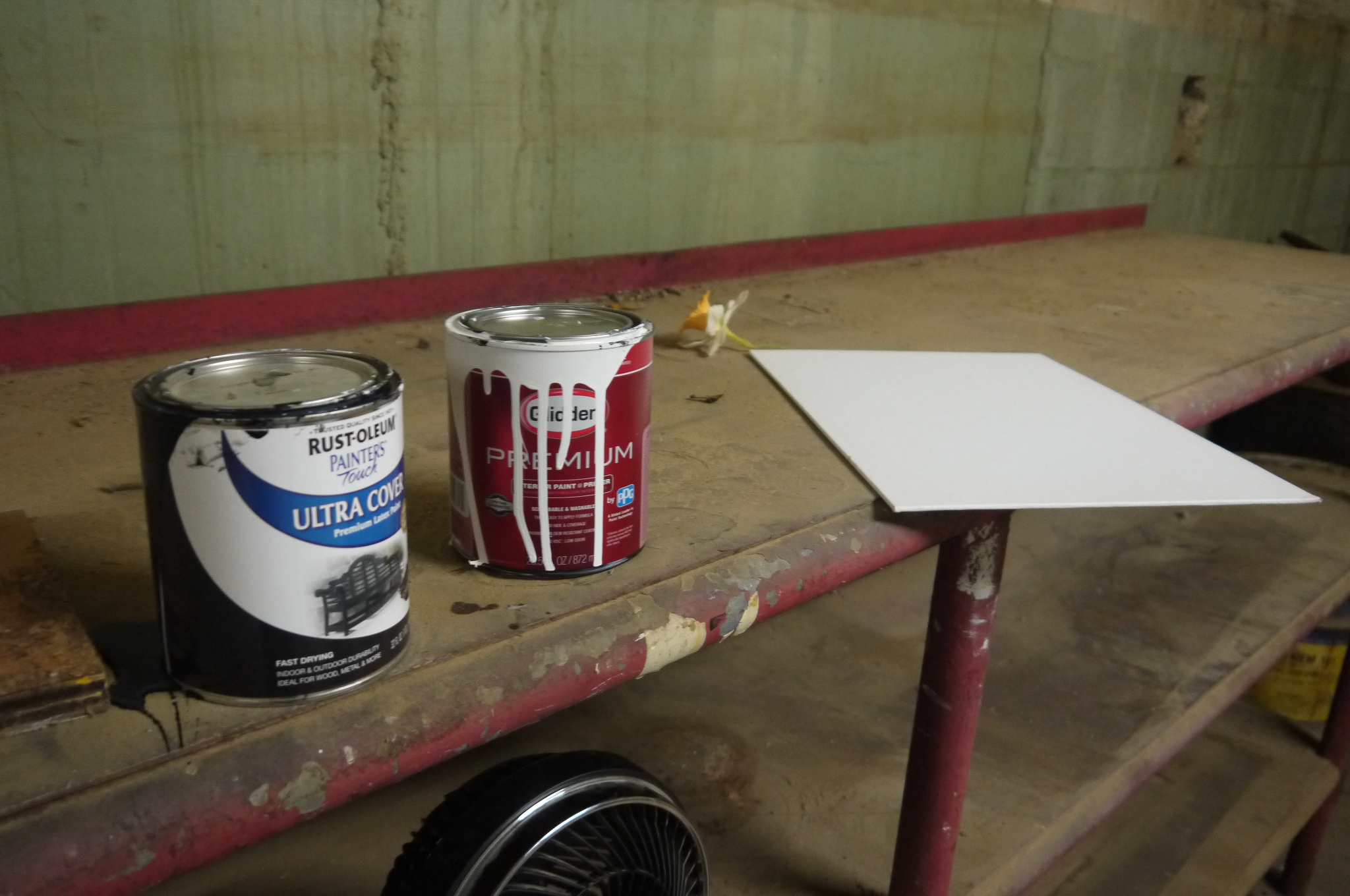 |
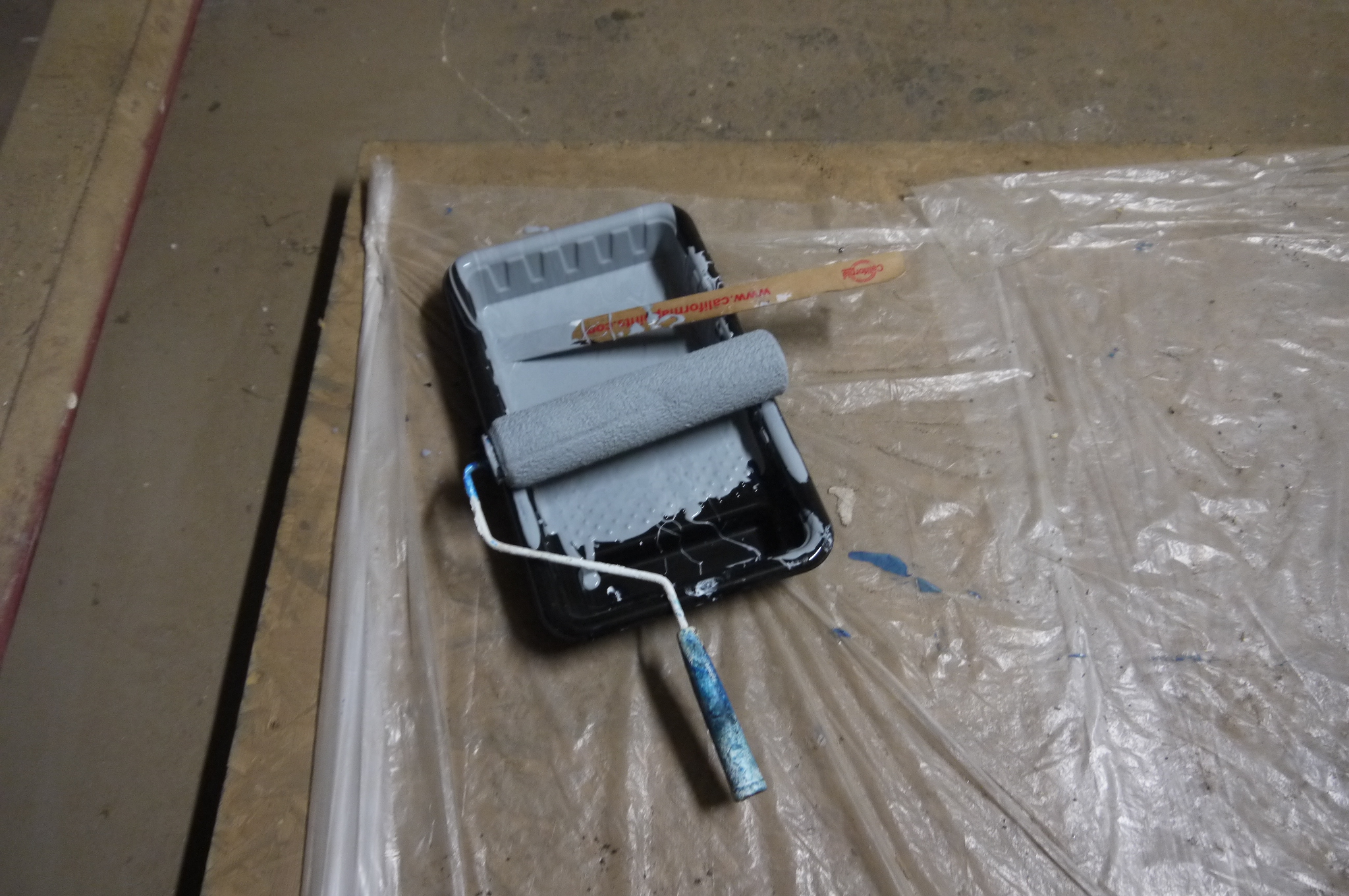 |
| I was fortunate to have a 'fine' roller brush on hand, and the surface came out great. About 6 hours later (with a small fan speeding up the dry-time) the table was ready for the robot. | 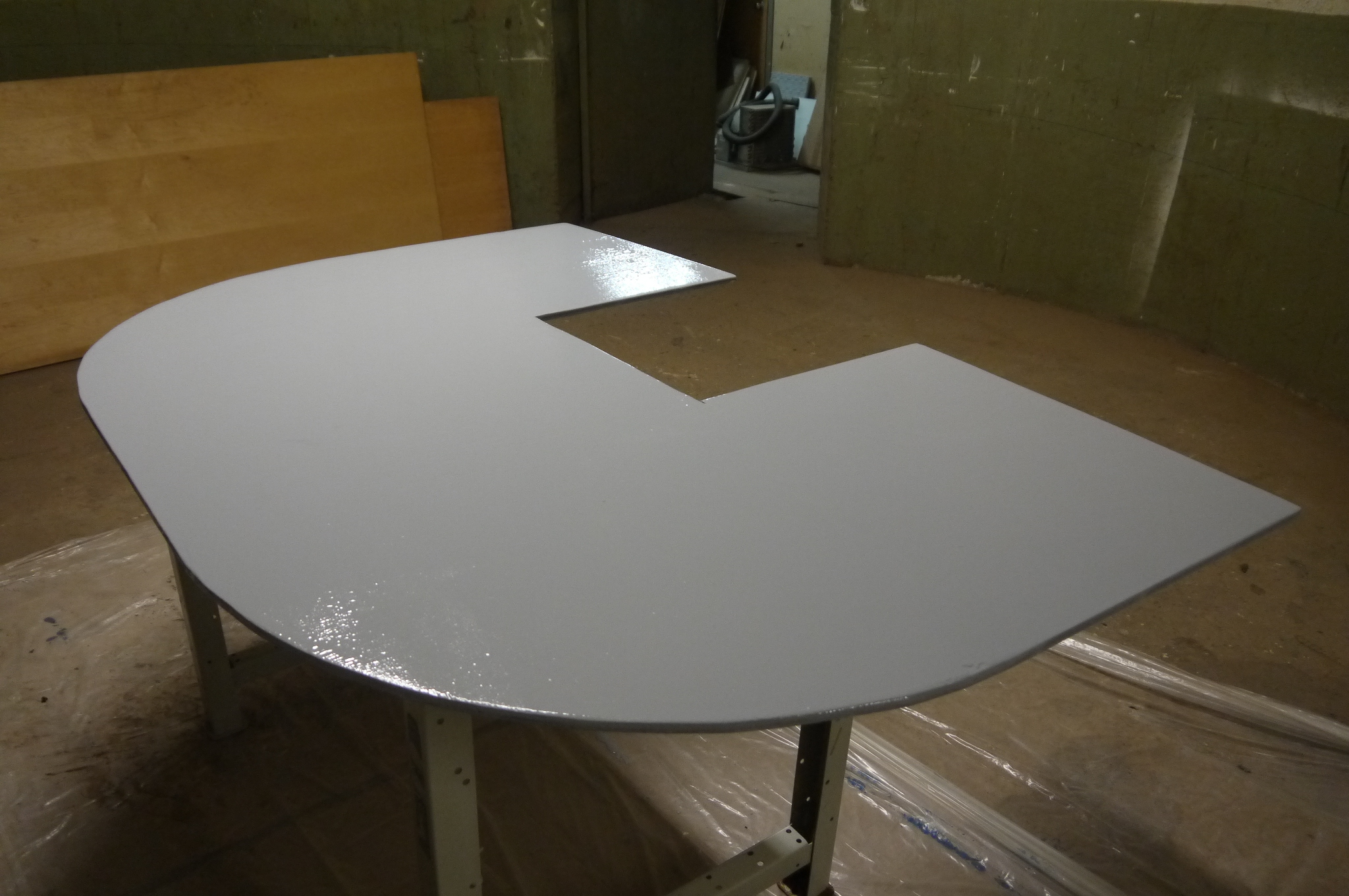 |
 |
| The table was tapped and set for M6 screws to hold it to the steel underbelly. Socket head cap screws with counter-sunk glued-in-place washers were used so that the screws didnt over-compress the wood work surface. | 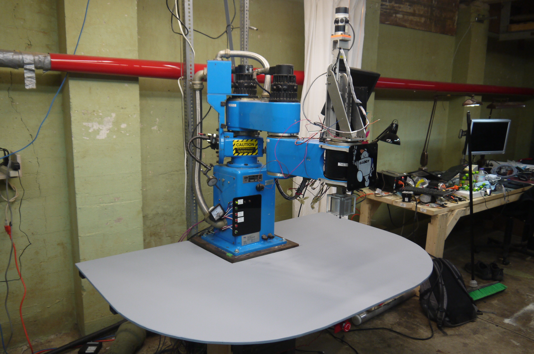 |
 |
| Some
table upgrades I found about 2 hours of downtime and some leftover RGB led strip from, the mighty kirkby, printed out some little brackets and tapped some M5 holes in the steel frame. Each little 3d printed bracket holds the led strip in place, some hot glue was used to keep everything in place while the brackets were being printed. There's a reasonable amount of RGB, which, eventiually will make its way to the MESA card for control. |
 |
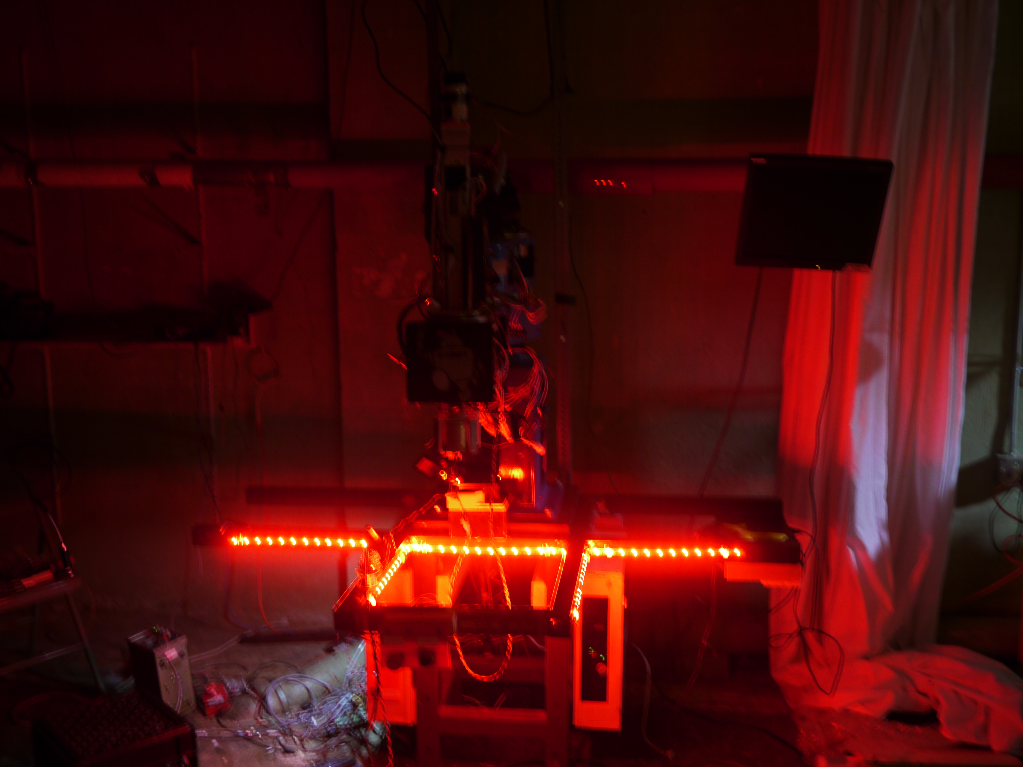 |
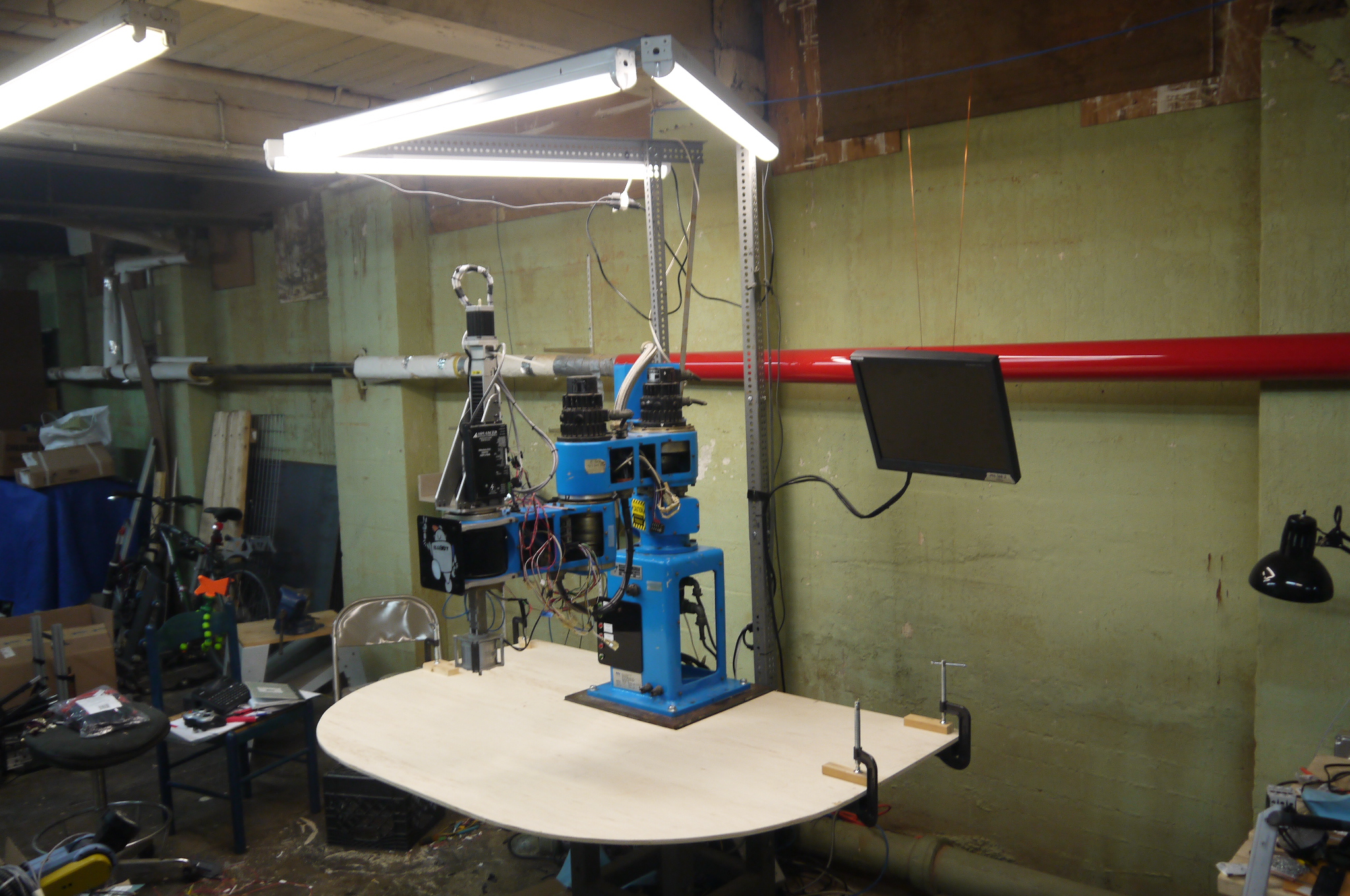
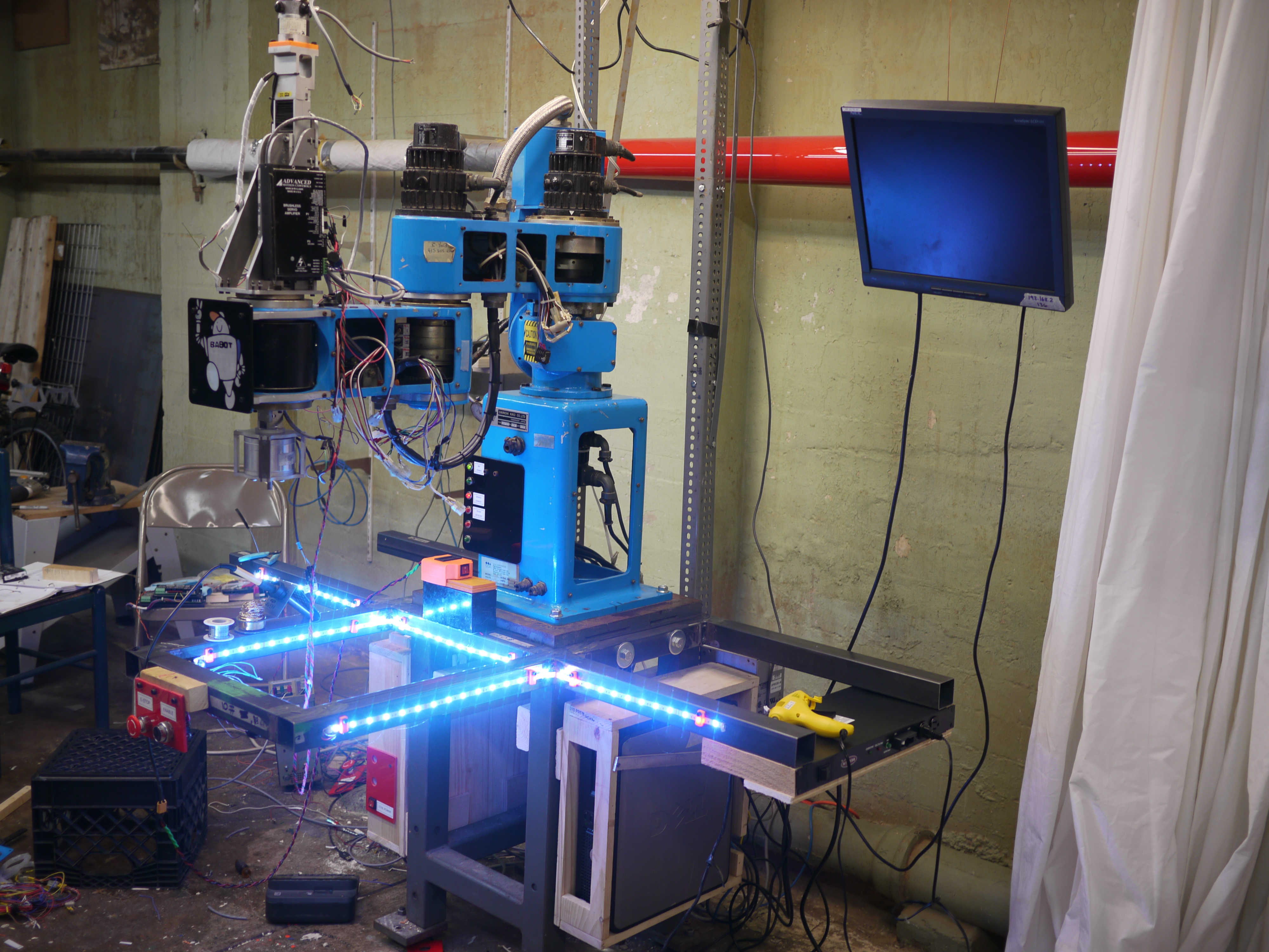
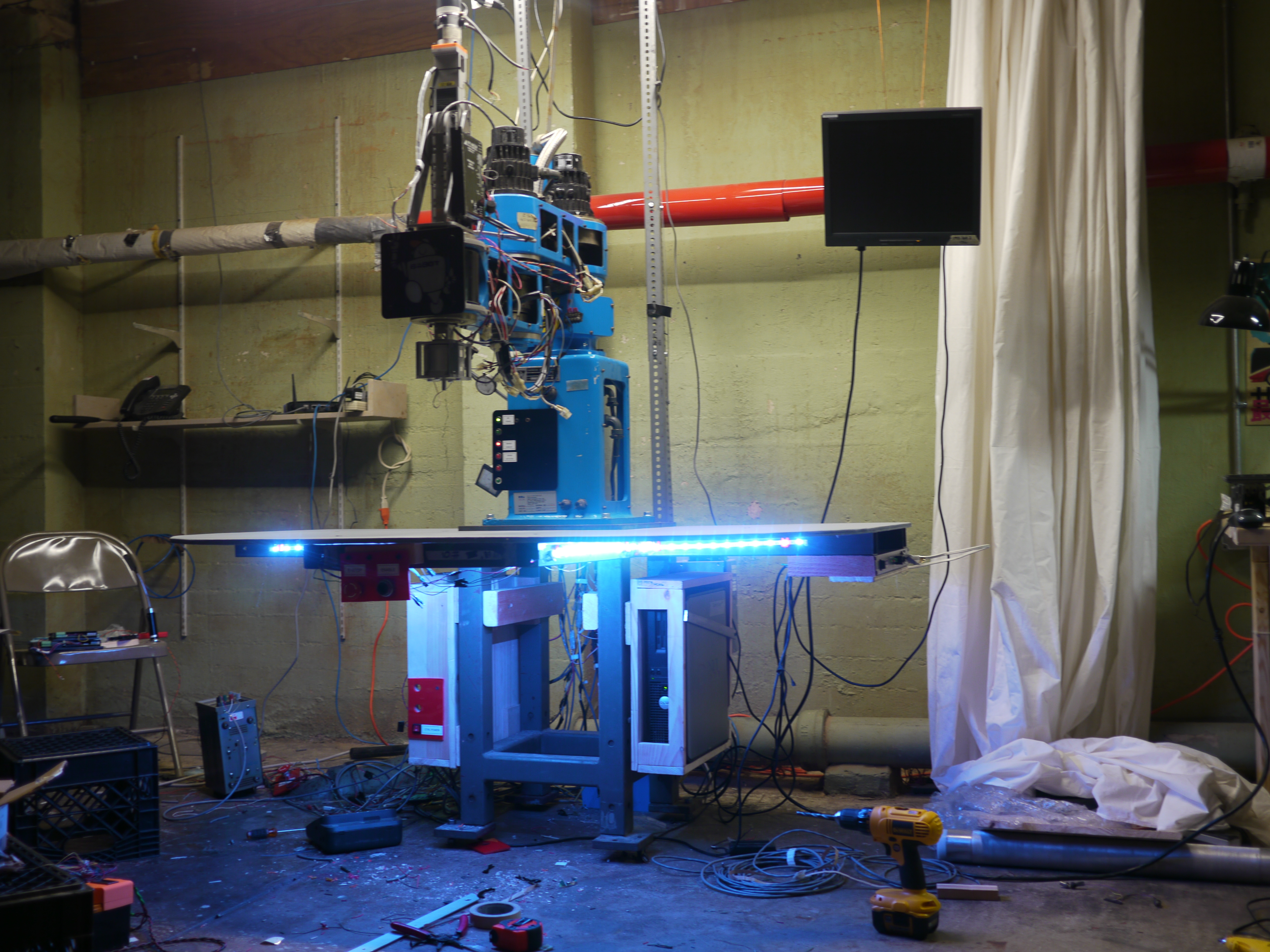
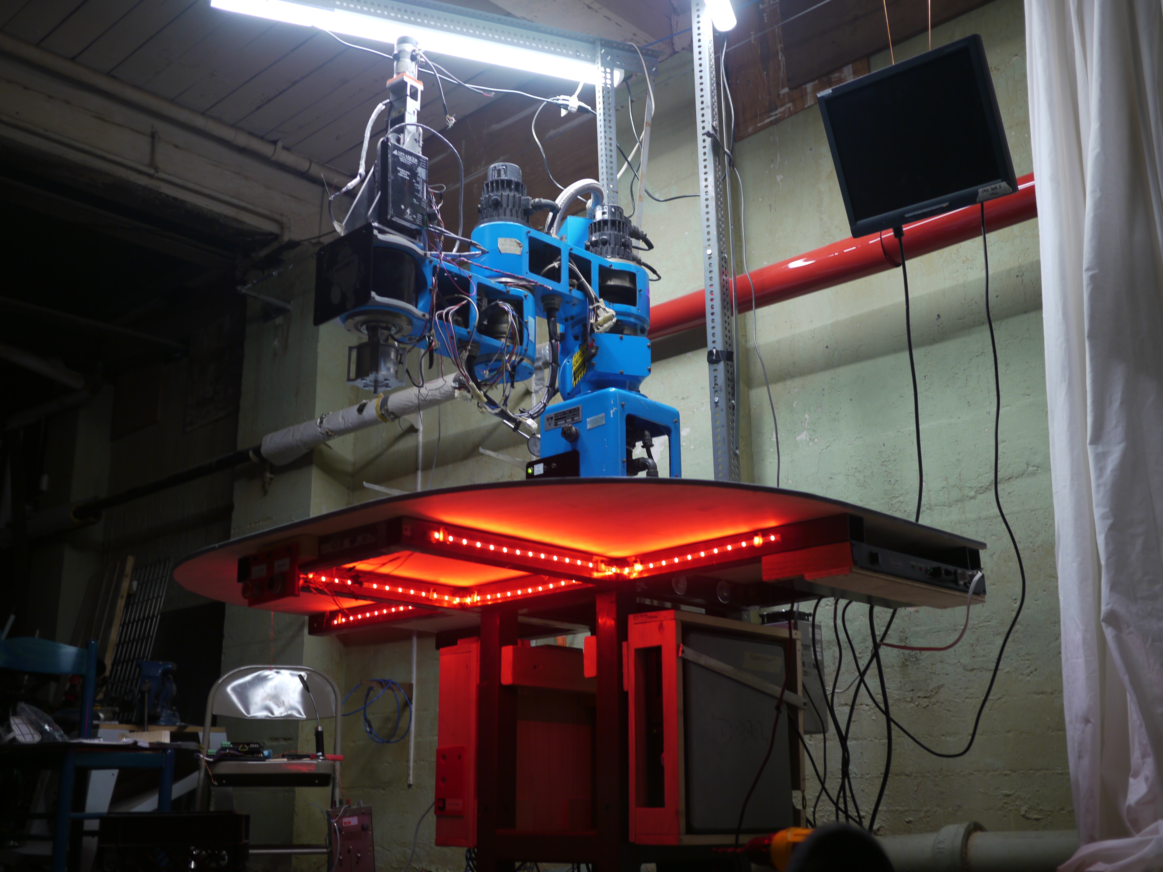
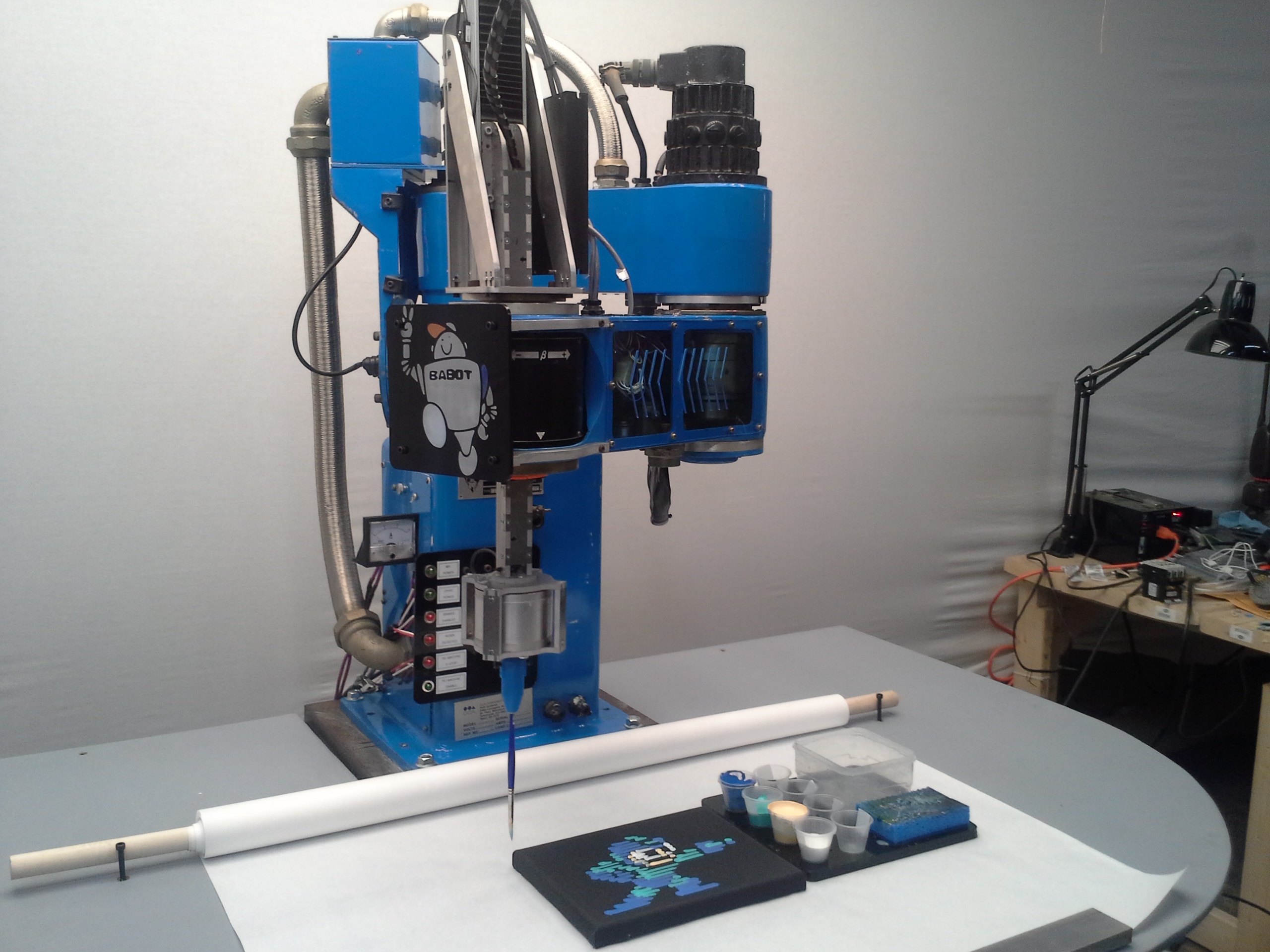
| With the
table installed, its quite the glowing saucer robot. Nominally the RGB led strip is about 30W with R,G,B running at 14v, this however is fairly small in comparison to the overhead lighting. If the overhead lighting is off or in a diminished state, it should make a cool effect, especially if RED is e-stop and GREEN is 'currently running a job, or some M-CODE'. Future improvements indeed. |
 |
 |
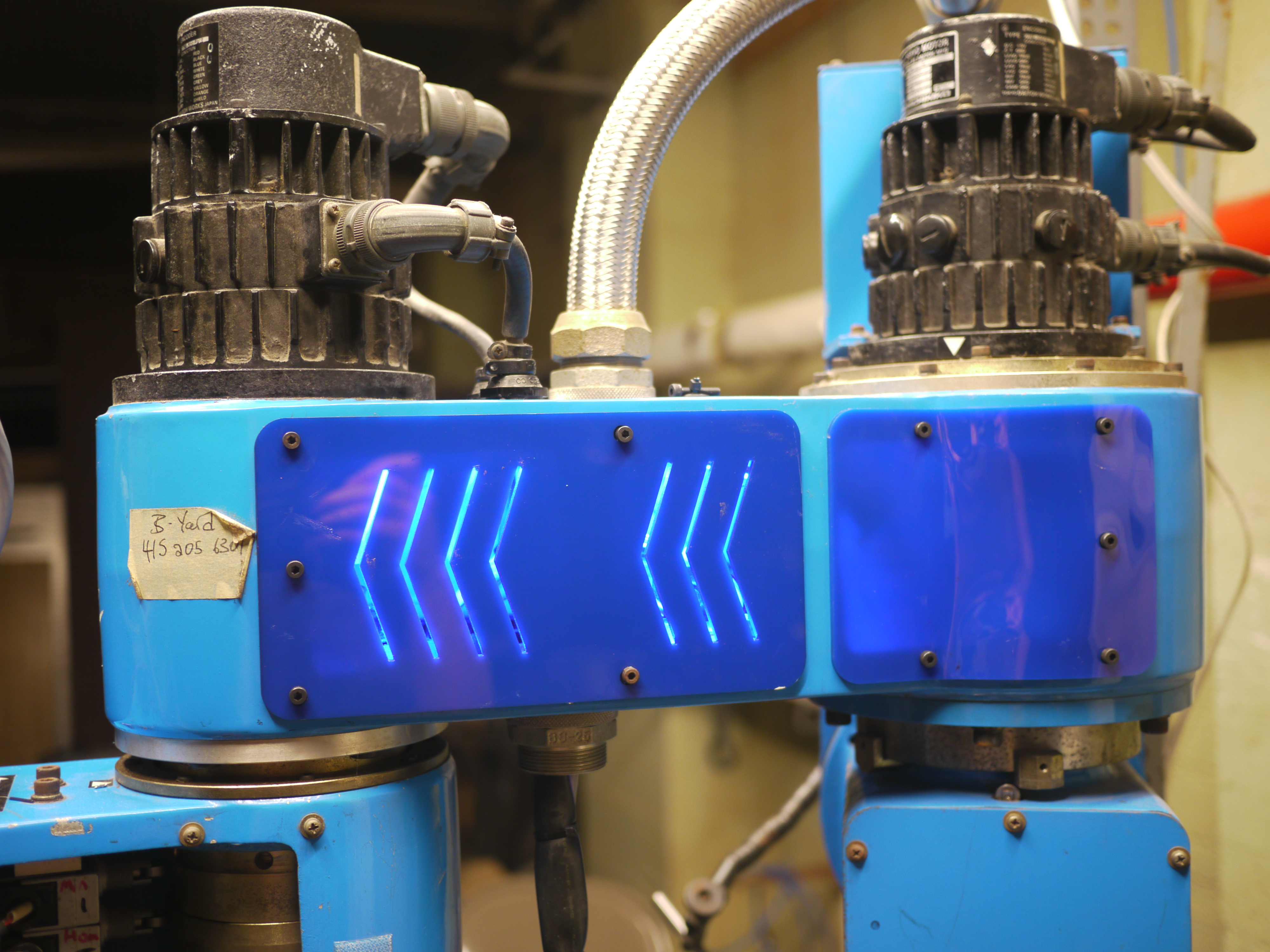
| Making
some cover panels Earlier the previous day, i made a quick sketch-model of the panel openings that were missing from the robot, i found some blue acrylic [link] and lasercut a rough pattern, using a hot air reflow gun I thermoformed the curved parts to match the robot, finally i added blue led strip for effect, because clearly the robots 'vents' should emit 'blue'. The remaining cabling is tied up and kept away from the moving belts inside the arm using some actual tapped-in anchors instead of the original sticky-zip tie mount (CMON GUYS) |
 |
 |
| Tidying
up with more cover panels I mistakenly brought the wrong extra blue acrylic with me and made the second cover panel clear-blue, with the same vent patten. I opted for some fairly 'open' tolerances on the mounting holes because the thermal forming is a bit of a curious action and its hard to quick-guess how much offset the curve makes. |
 |
 |
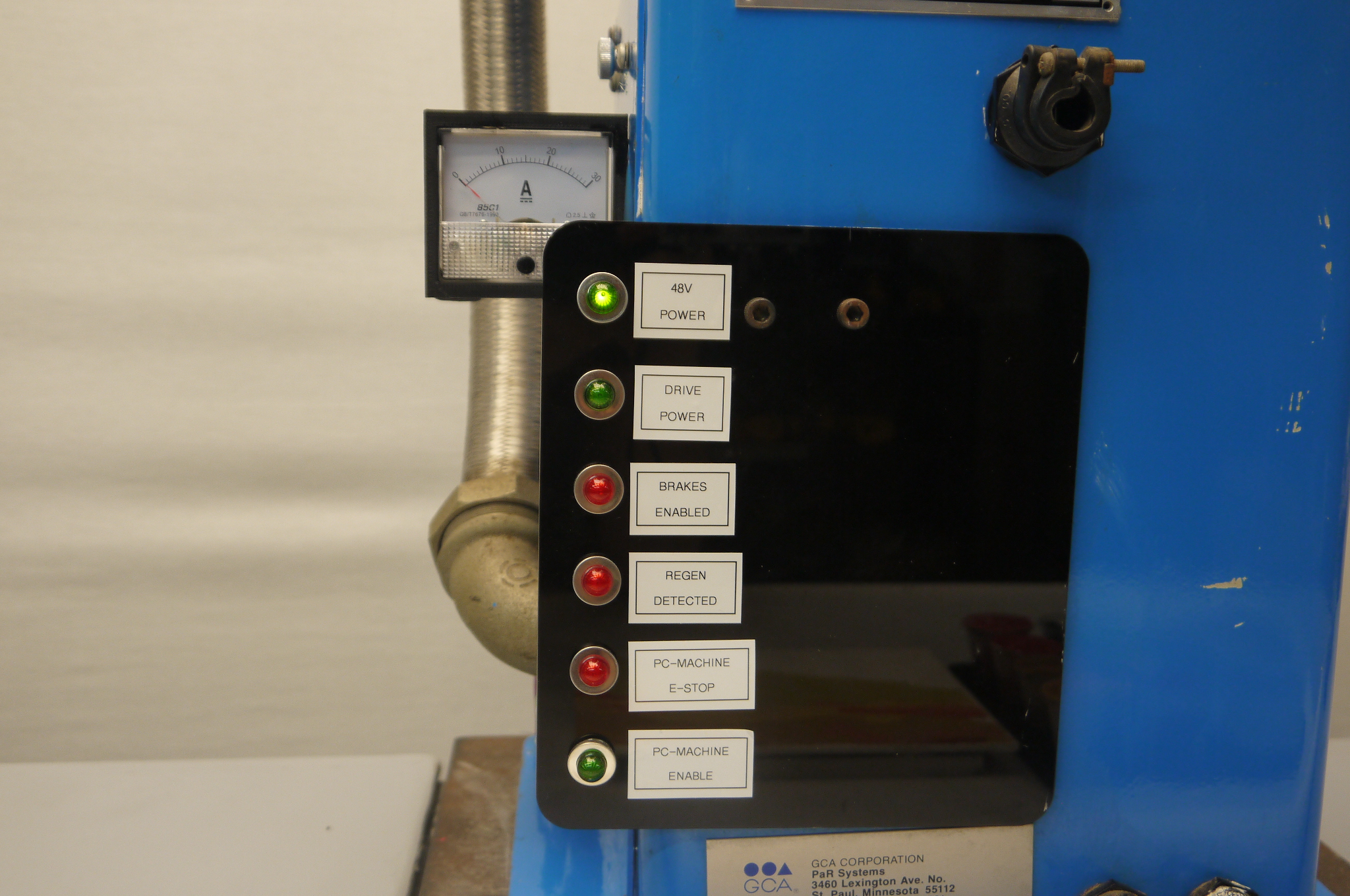
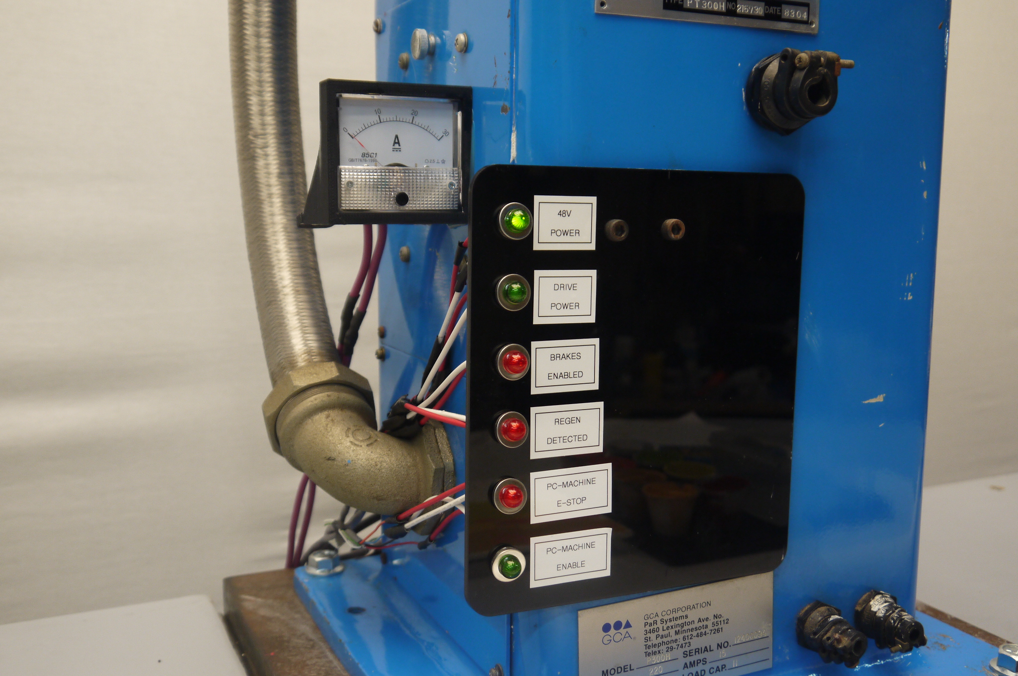
| Indication This was fairly helpful, sometimes its hard to see where / what was going wrong. This indication panel consist of six 24v leds wired to different parts of the robot, both on the power and control side of the bot. Admittedly i laser-cut this panel before figuring out what I was plotting to put in each spot. Indications that were the most useful were 'do the frigging servo drives have power' and 'wait is it still in e-stop'. The ammeter was also useful for keeping track of the 48v bus current draw |
 |
 |
| Control Topology Overview |
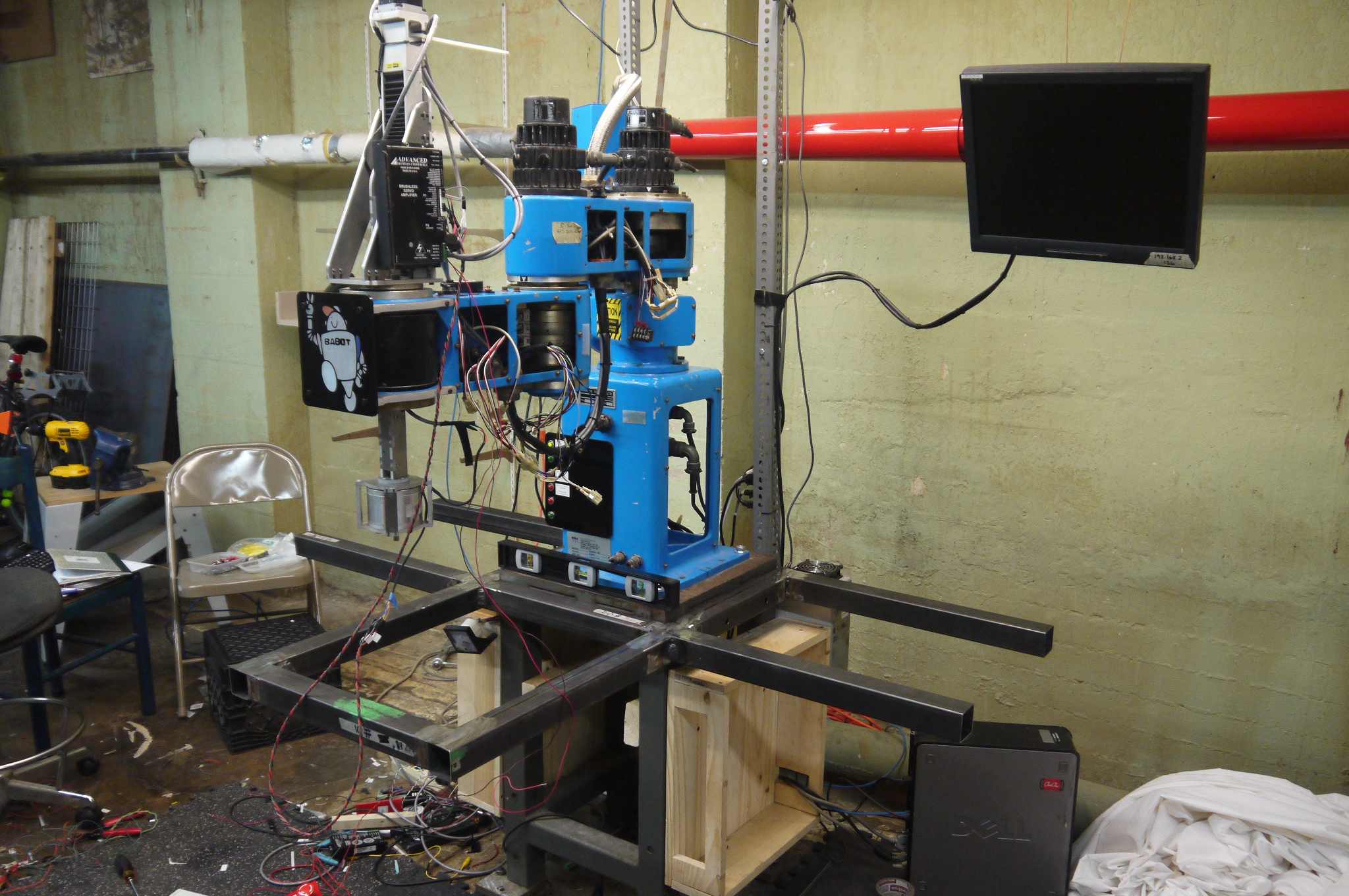
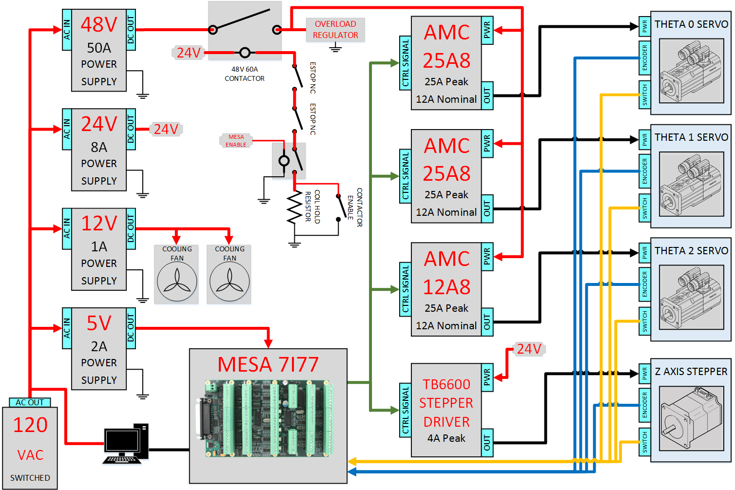 High level overview of
the controls system for BLUEBOT: High level overview of
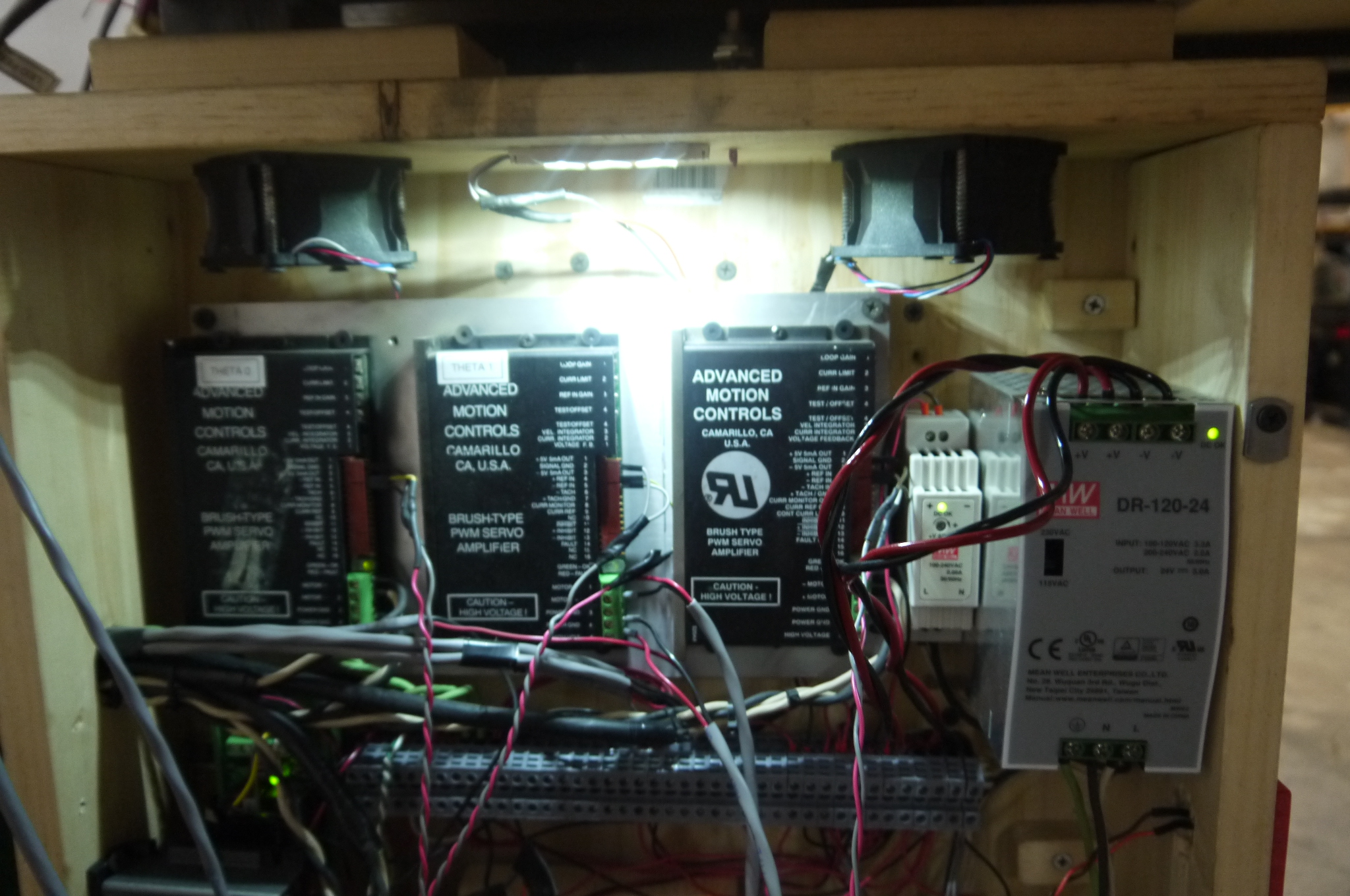
the controls system for BLUEBOT:The main supply for the three main servo drives is a monsterous 40A 48V supply. An overload rregulator is used to prevent regen-current from quickly reversing motors. This overload regulator dumps any overvoltage conditions into waste heat. The 24V subsystem feeds control logic and main power for the Z-Axis stepper motor driver. The 12V supply is used to feed internal lighting inside the control cabinet along with the coolant fans to keep the supplies and servo drives cool. Finally the 5V supply feeds logic, the MESA 7I77 and externally feeds the (rather hungry) motor encoders. The servo drives (AMC 25A8 / 12A8) were surplus units, nominally from ebay / laboratory clean-outs. Each of the servo controllers are mounted on an aluminum plate for better thermals. |
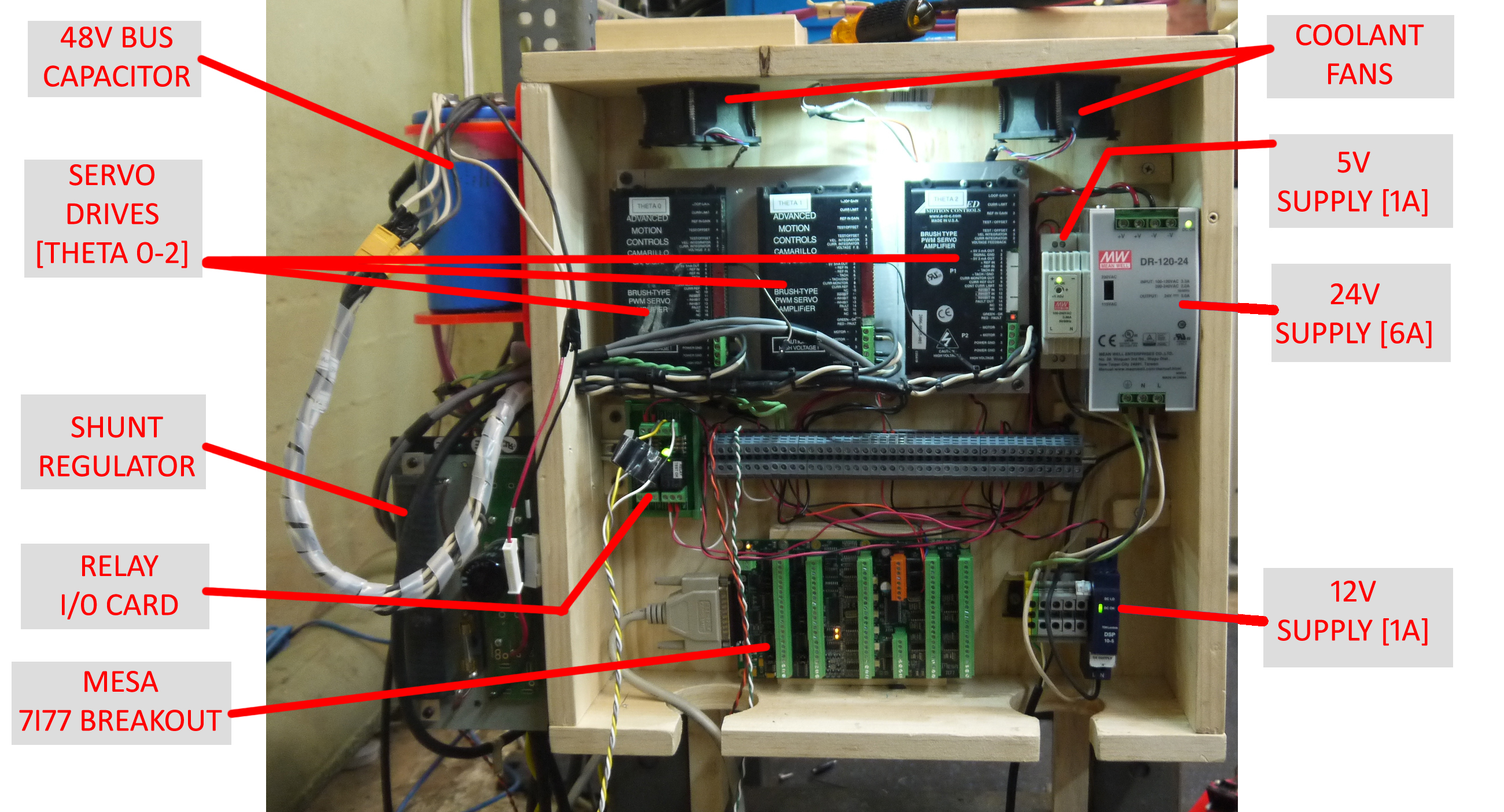 The actual control box is
a bit of an array of parts. Its was difficult to
determine 'how much space will everything take up'
without actually having all the parts on hand. A
few things were learned during reverse
engineering the robot, which resulted in some parts
being larger than expected. The encoders each pulled
250mA at 5v, so a solid supply was needed, the
electric spring loaded brakes on each axis, each
pulled 1A at 24v, so an oversized 24v supply was
needed. The regen on the controllers was sizable
enough to cause over voltage on the main supply, so a
shunt regulator was acquired [link] [local data sheet] The actual control box is
a bit of an array of parts. Its was difficult to
determine 'how much space will everything take up'
without actually having all the parts on hand. A
few things were learned during reverse
engineering the robot, which resulted in some parts
being larger than expected. The encoders each pulled
250mA at 5v, so a solid supply was needed, the
electric spring loaded brakes on each axis, each
pulled 1A at 24v, so an oversized 24v supply was
needed. The regen on the controllers was sizable
enough to cause over voltage on the main supply, so a
shunt regulator was acquired [link] [local data sheet] |
| Adding Controls and Power Parts | ||
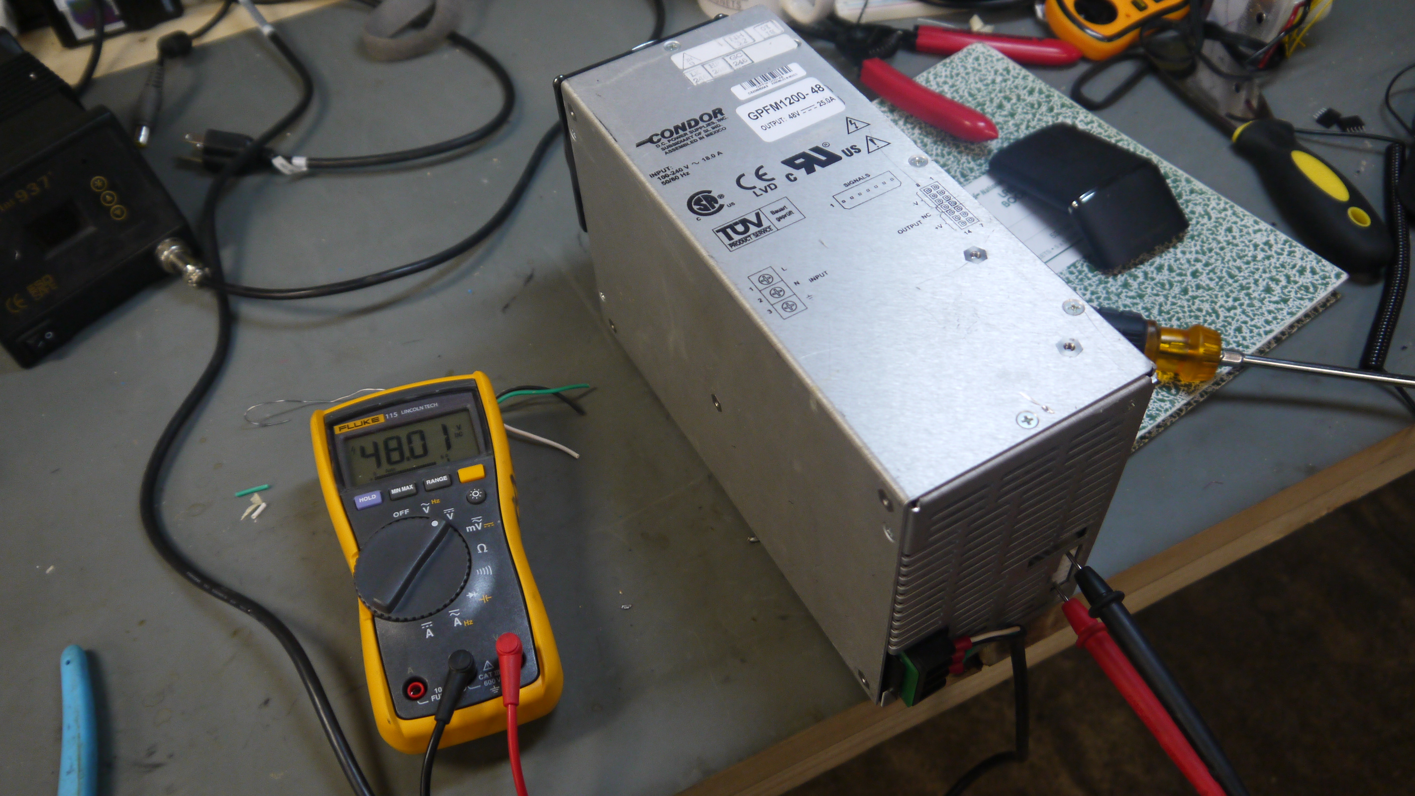
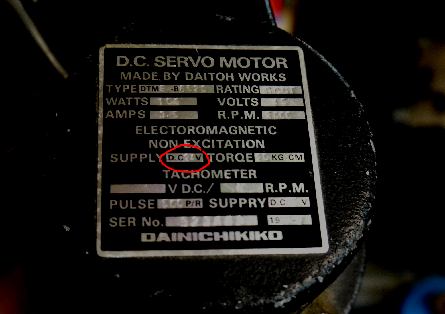
| From poking around the robot, I found that each of the theta motors were DC Brush, 48V. The label was, curious, as it rated the motor for continuous: 100W, 48v 3.5A. Thats bizarre, 3.5A * 48V is 168W not 100W. Bizarre. Continuous current rating and impulse current rating are also incredibly different things. The AMC 12A controllers can be set to operate at lower currents, but some evaluation regarding what is reasonable is needed. For robot-power i'm using a recycled 48v 25A supply. More on that later. | 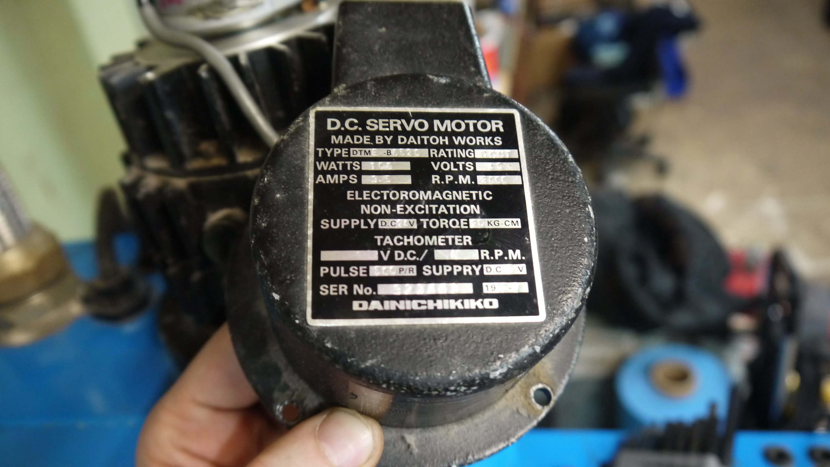 |
 |
| BRAKES Each of the theta motors contains a spring loaded brake and an encoder. The brake topology is active-off, supply power to enable. Supply power for the brakes is 24v, and nominally about an amp. They actually disengage well below 24v, so i may try and minimize brake heating (and possible failure) by limiting the steady state current to the motor brakes. This is sometimes done on industrial contactors (commercially called 'economizers'). |
 |
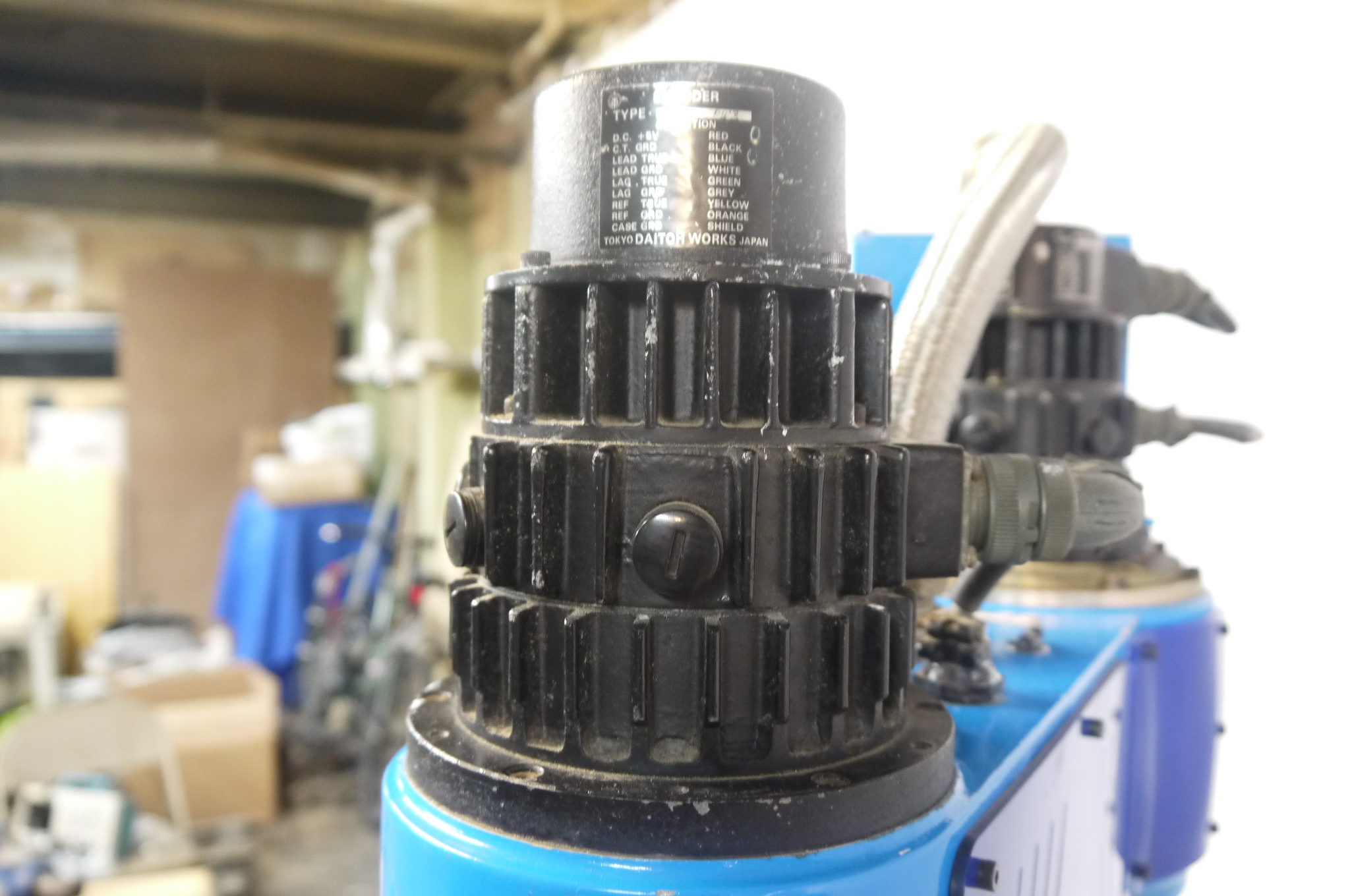 |
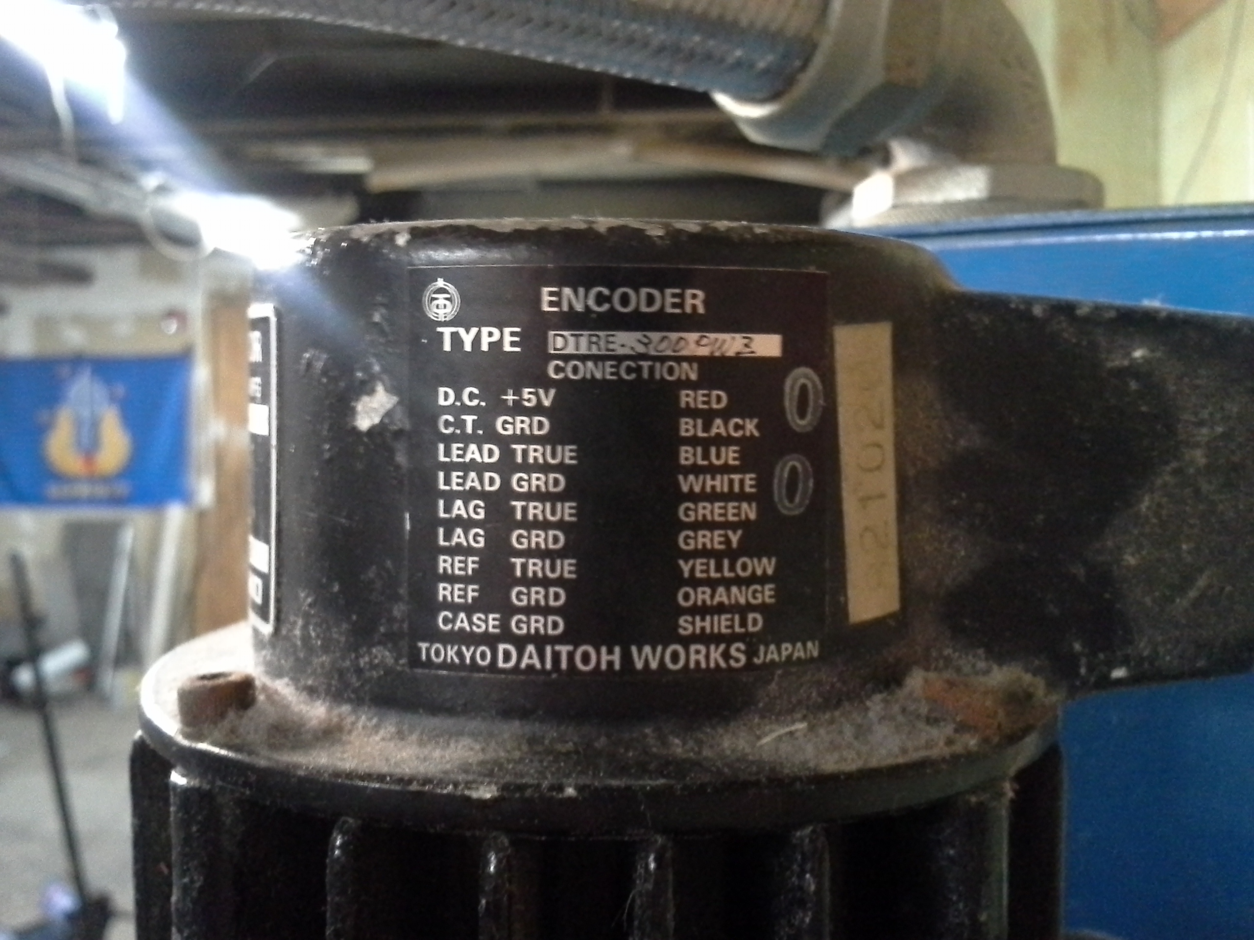
| ENCODERS The encoders on each theta are the same model, single-ended A/B + Index, 500 count per revolution. For whatever reason encoder channel A / B is labeled LEAD / LAG, and INDEX is labeled REF. The supply is labeled 5v, which is quite convenient . |
 |
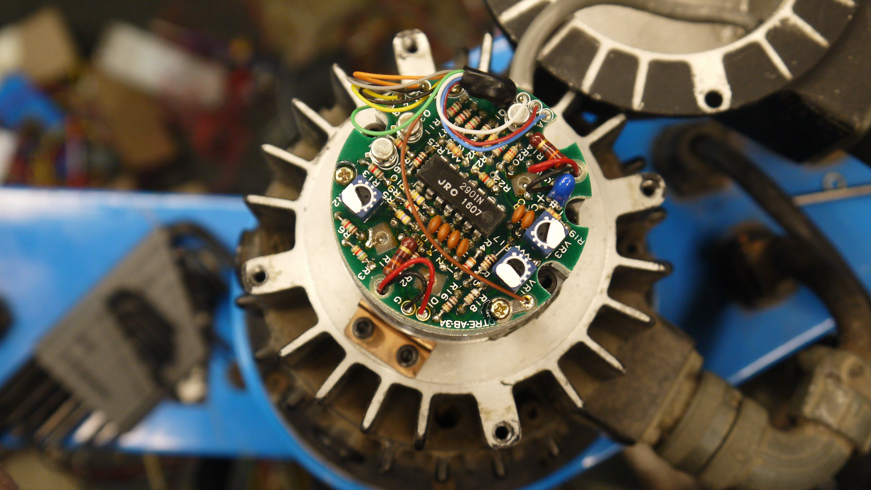 |
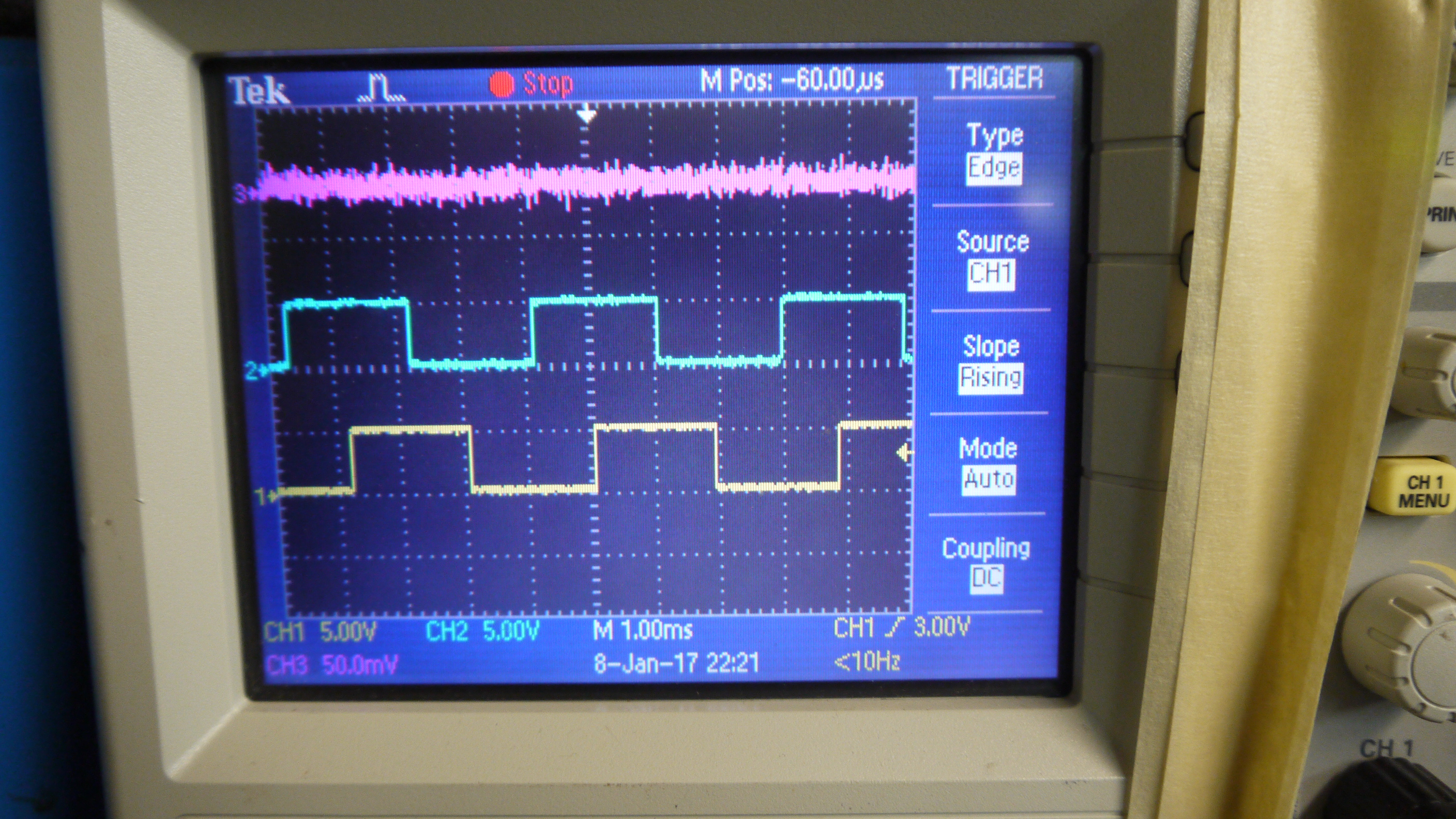
| I wanted to verify the encoders worked, as i didnt have scope probes long enough, I taped an oscilloscope to the robot and a power supply way up top. Initially scoping the encoder, powered by 5v with an external supply, was fruitless, there was a barely visible ~100mV square wave per channel. After some frustration, I found that this particular series of encoder was open-collector, so, a quick 1K pullup resistor later and I had some nice clean encoder pulses. | 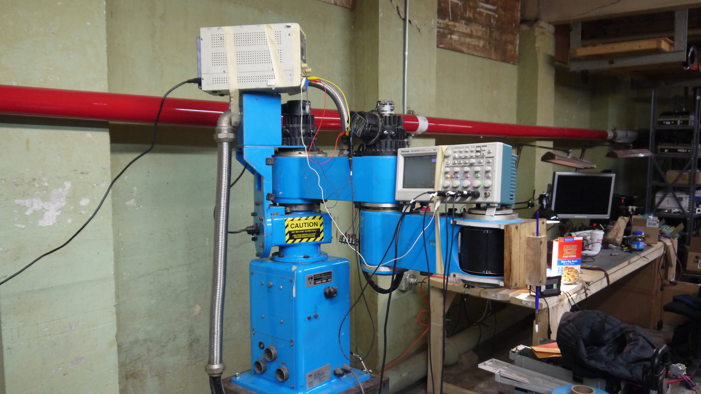 |
 |
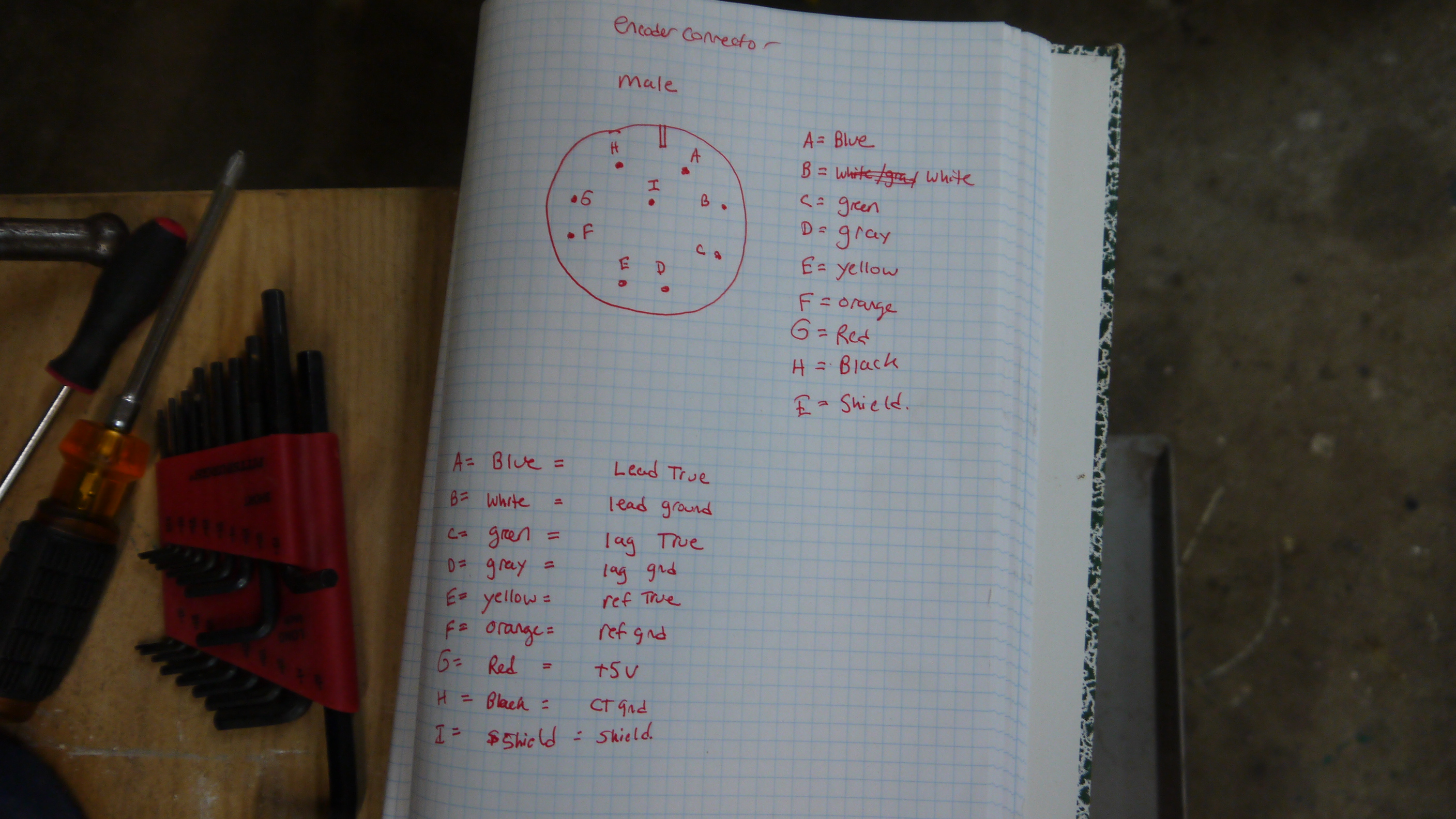
| BEWARE OF WIRE COLORS I was quite happy that the encoders had the signals labeled with wire colors, but then noticed that it just mated to a connector, and those colors were meaningless. So I went through and metered-out each of the pins to the board to come up with a circular connector pinout. |
 |
|
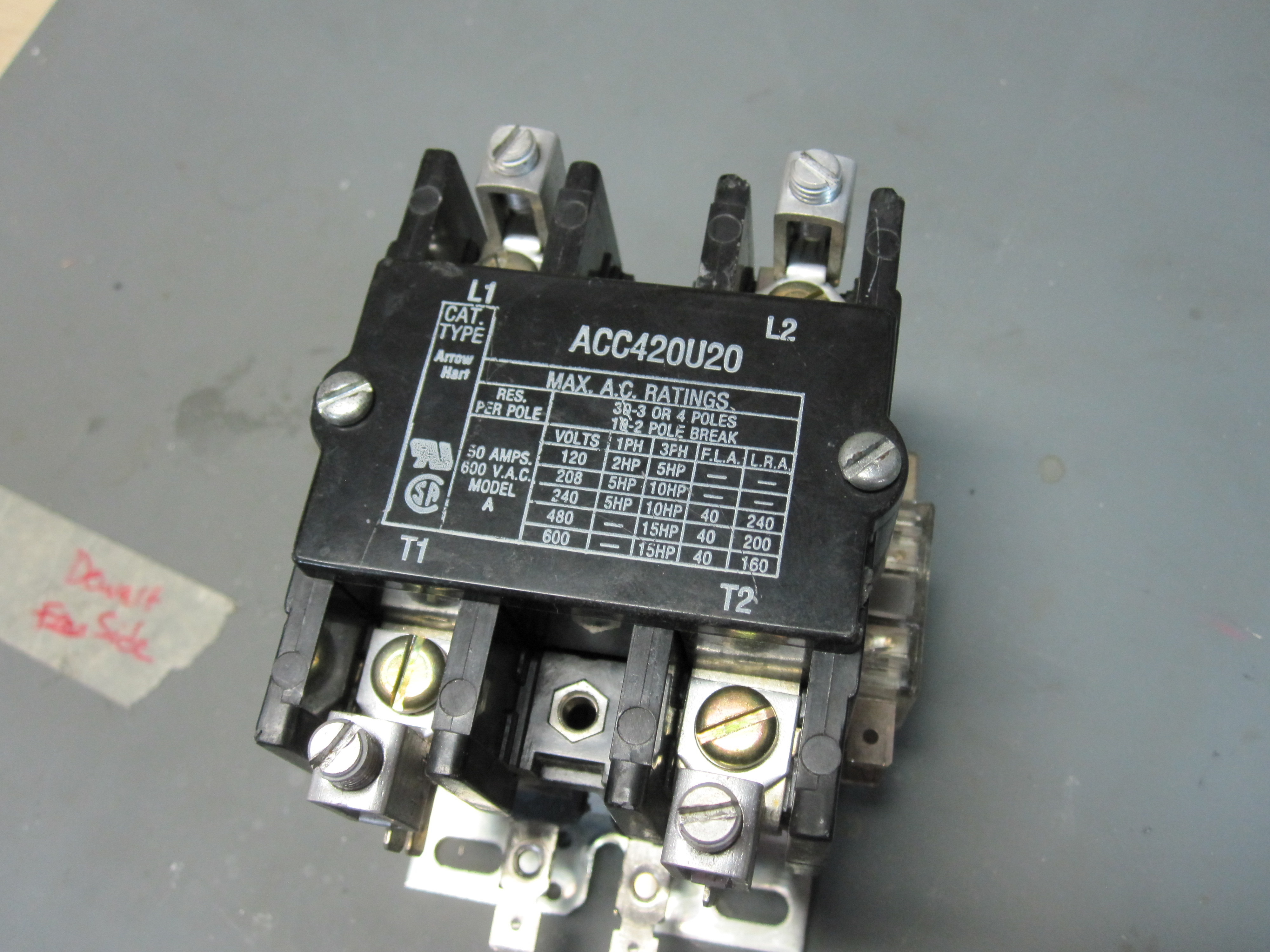
| E-STOP Contactor of Glory In the case where emergency-stop is required, i'd like to be able to kill power to all the servo drives, not just to 'command stop the sevro drives' To do this I needed something to interrupt the main DC supply. This 60A contactor was scavenged from previous research projects at the NRL. Unfortunately it had a 120vac 'coil' drive, whereas i'd rather actuate it with lowvoltage DC. |
 |
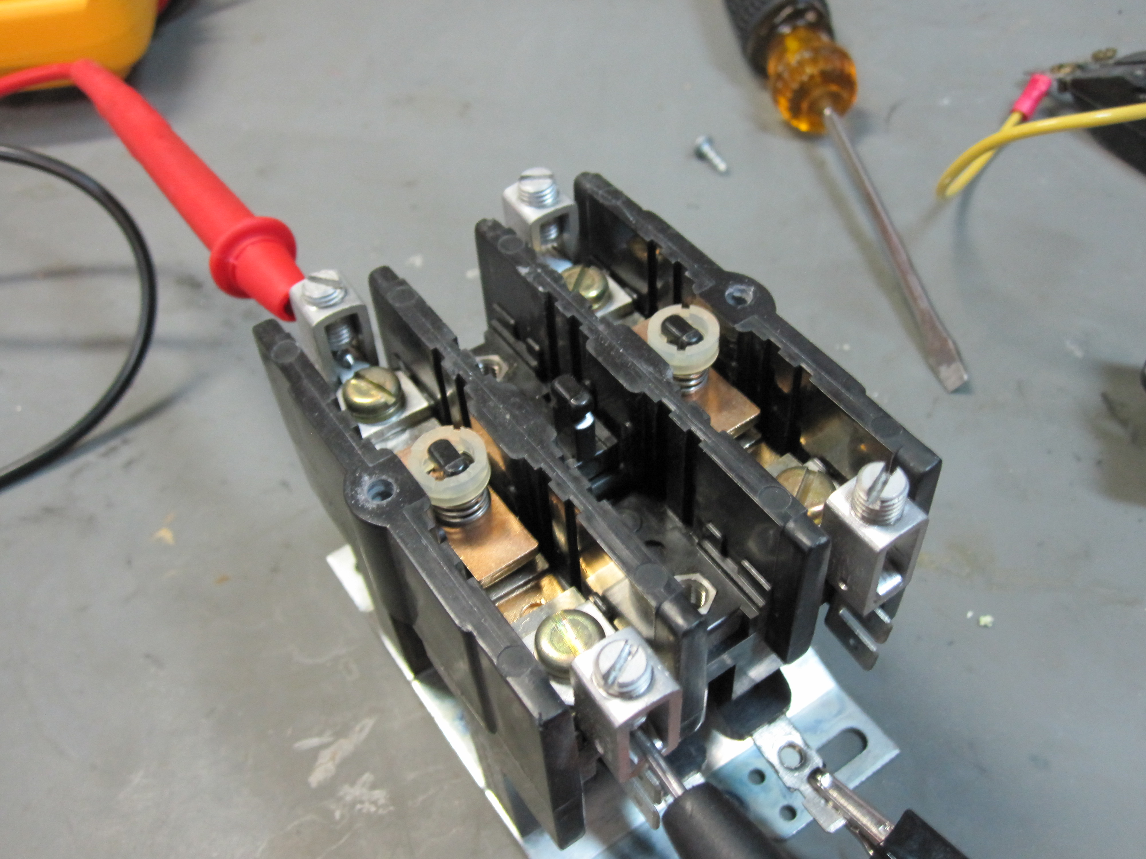 |
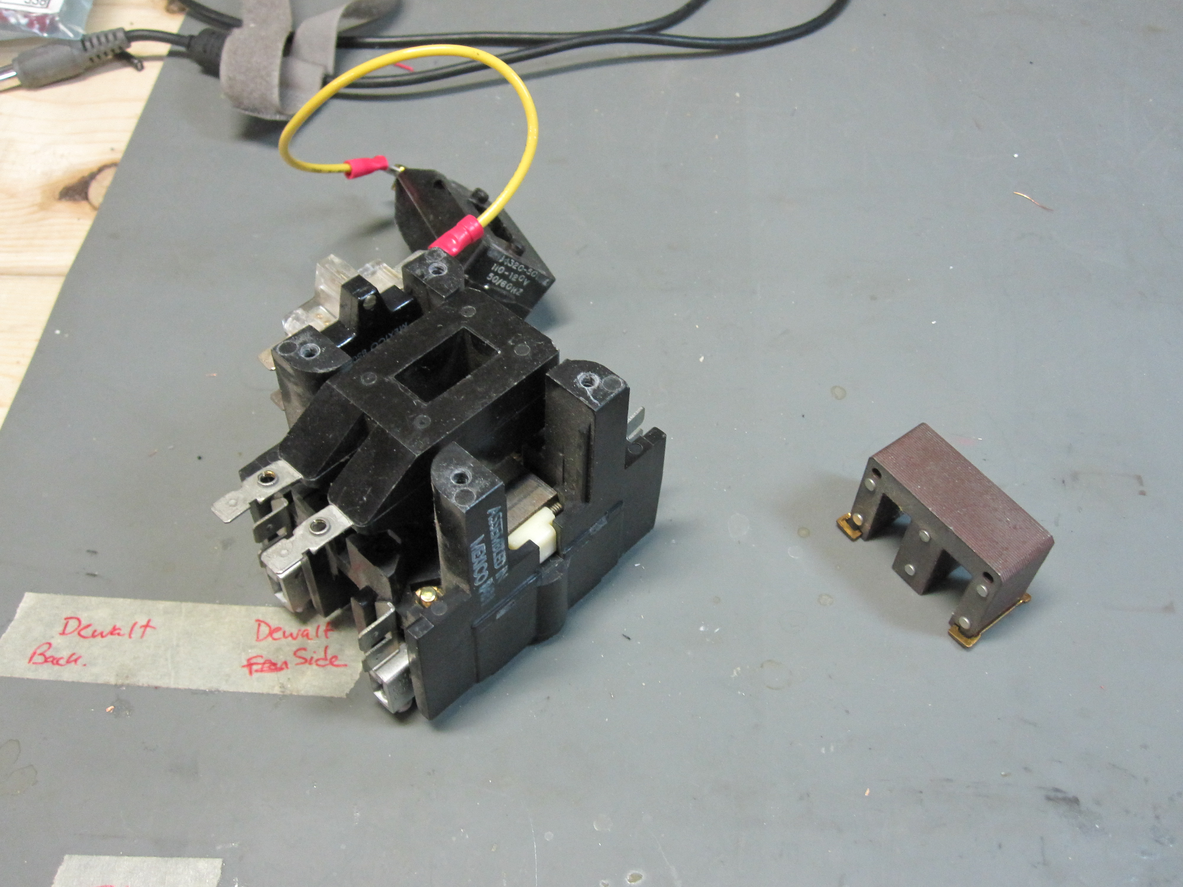
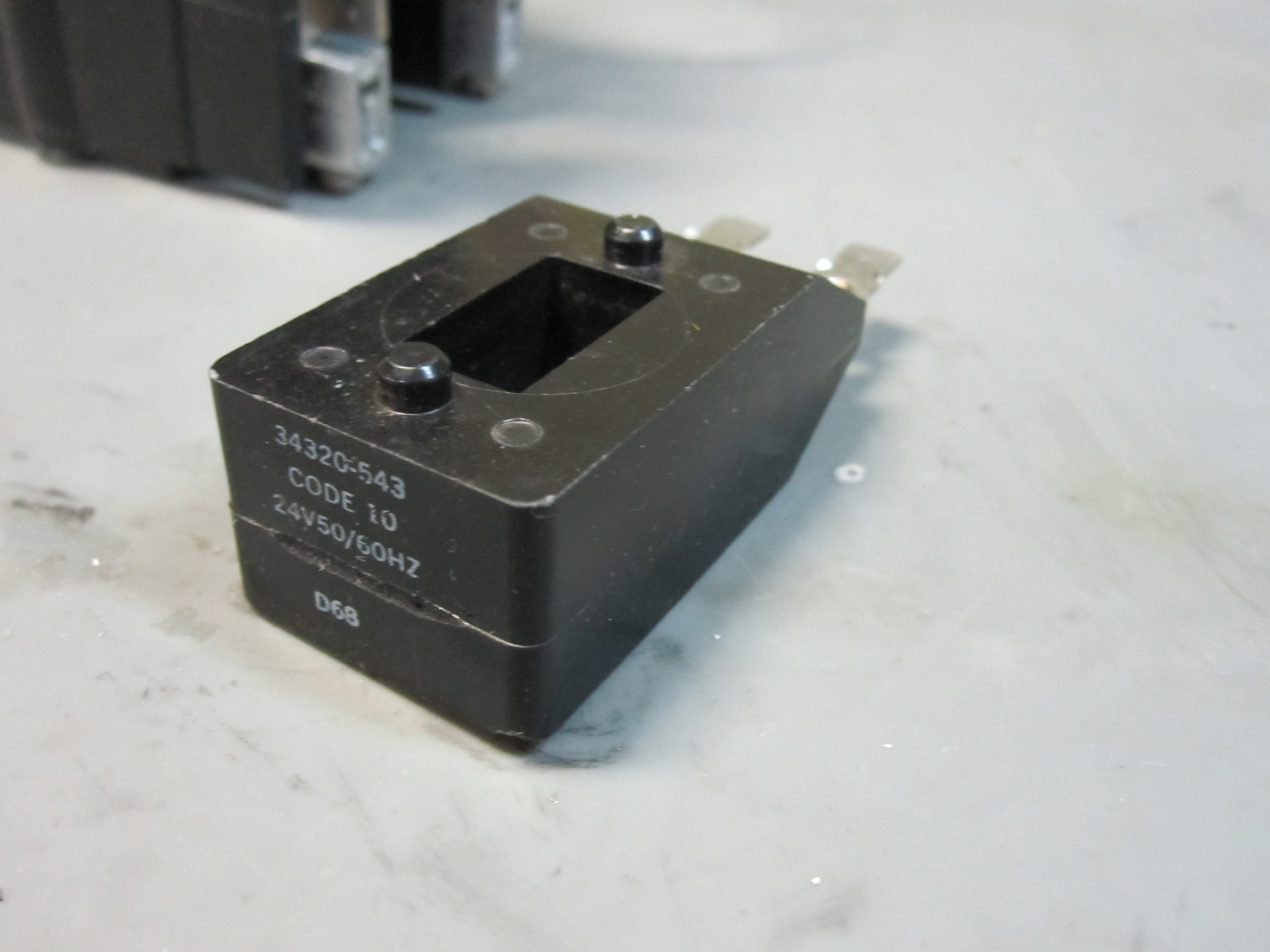
| Converting the contactor to lowvoltage DC Initially i planned to 3dprint and wind an appropriate sized coil for the contactor, but was fortunate to find a 24vac version on ebay. The 24vac coil operates, nominally, at 8v dc. To actuate the contactor a 24v supply and current limiting resistor is used for steady state operation. The 'swap' was quite simple, unscrew the bottom, pull out half the e-core swap the rectangular potted coil, and put back together. Back in business. The giant-ness of this thing does result in a quite-excellent 'ka-chunk' when enabled. |
 |
 |
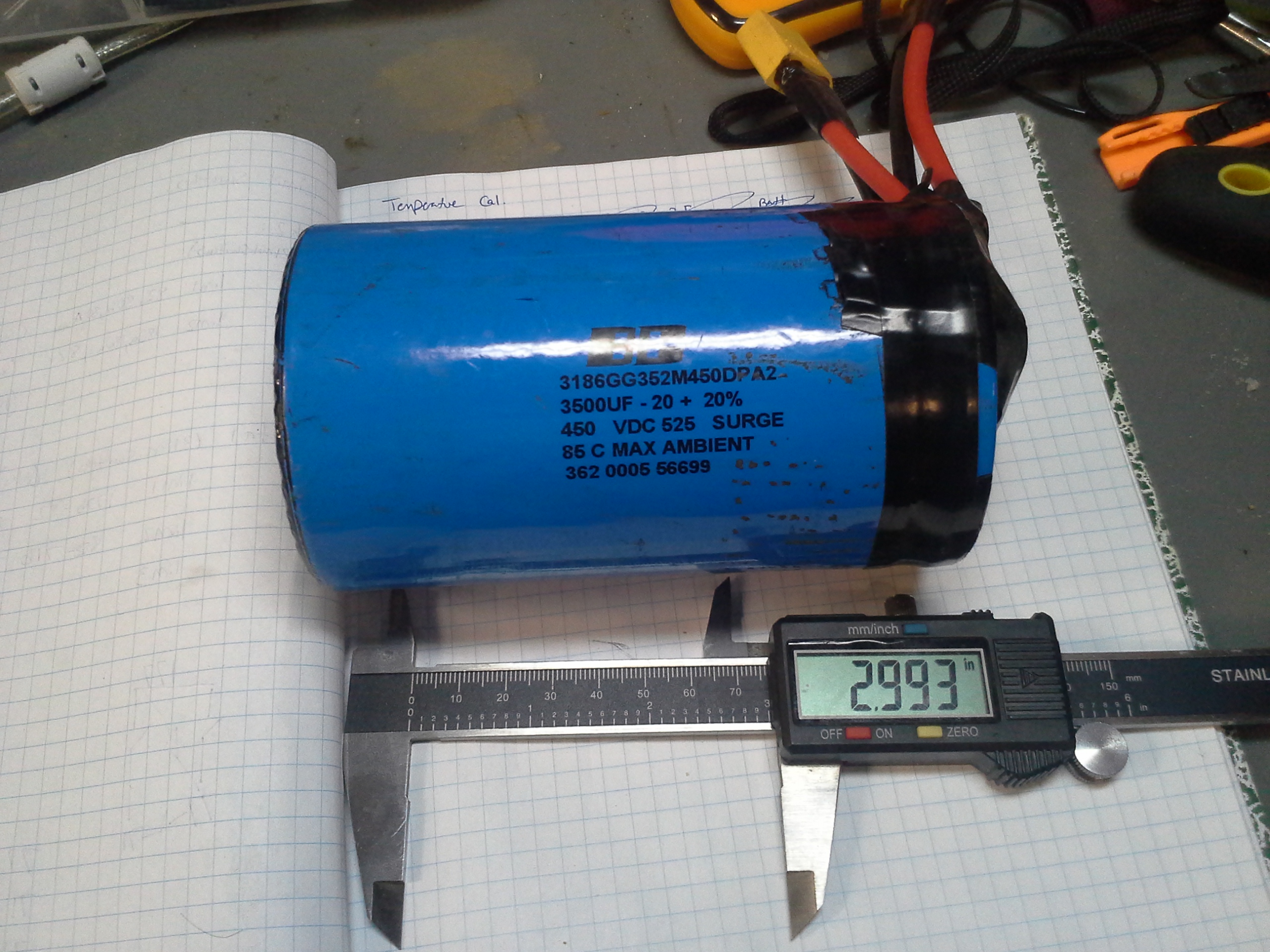
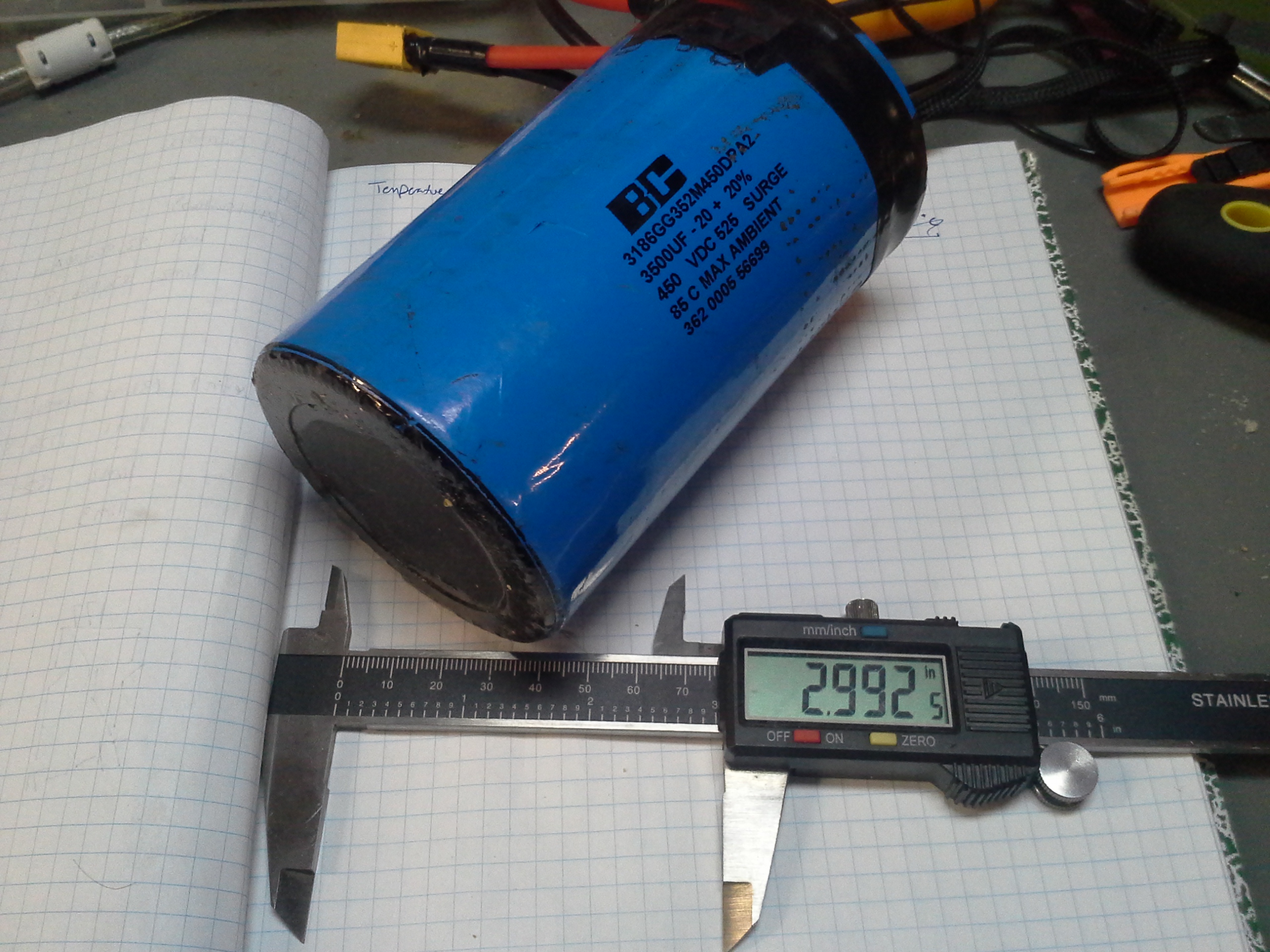
| MEGACAP This was actuall a left-over from the great battlebot adventure. Its a low-esr 3500uF 450V cap. Nominally i would probably have been better off using a lower voltage higher capacitance cap, but this was already hanging about and was available. I ended up laser-cutting an enclosure for it to hold it in place behind the robot. Having this in place reduces the ripple current each of the servo drives sees on their respective dc rails. |
 |
 |
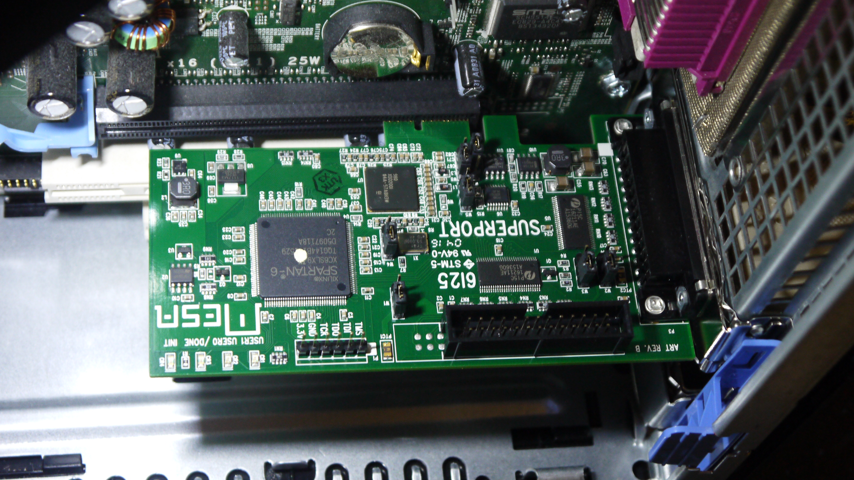
| Servo Drives Each of the axes has a servo drive as its power stage. Normally the feedback loop is closed at servo drive itself, with the encoder feeding into the drive's encoder input. As shown by the main system diagram, the encoders feed directly back into the host PC, bypassing the servo drives. As such the drives (AMC 12A8 / 25A8) are reduced a bit to current limited 4 quadrant supplies. The analog output from the servo card ties into each drives +/- 10v analog control input for control. Each of the drives is mounted to a large aluminum heatsink plate and cooled by overhead fans. Shown far right is the MESA control card |
 |
 |
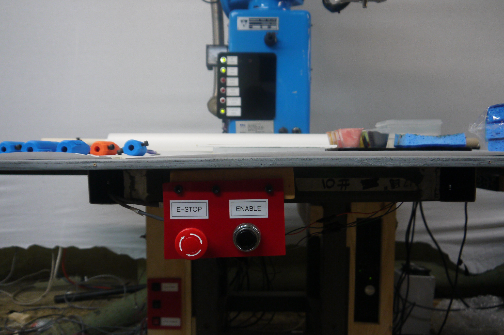
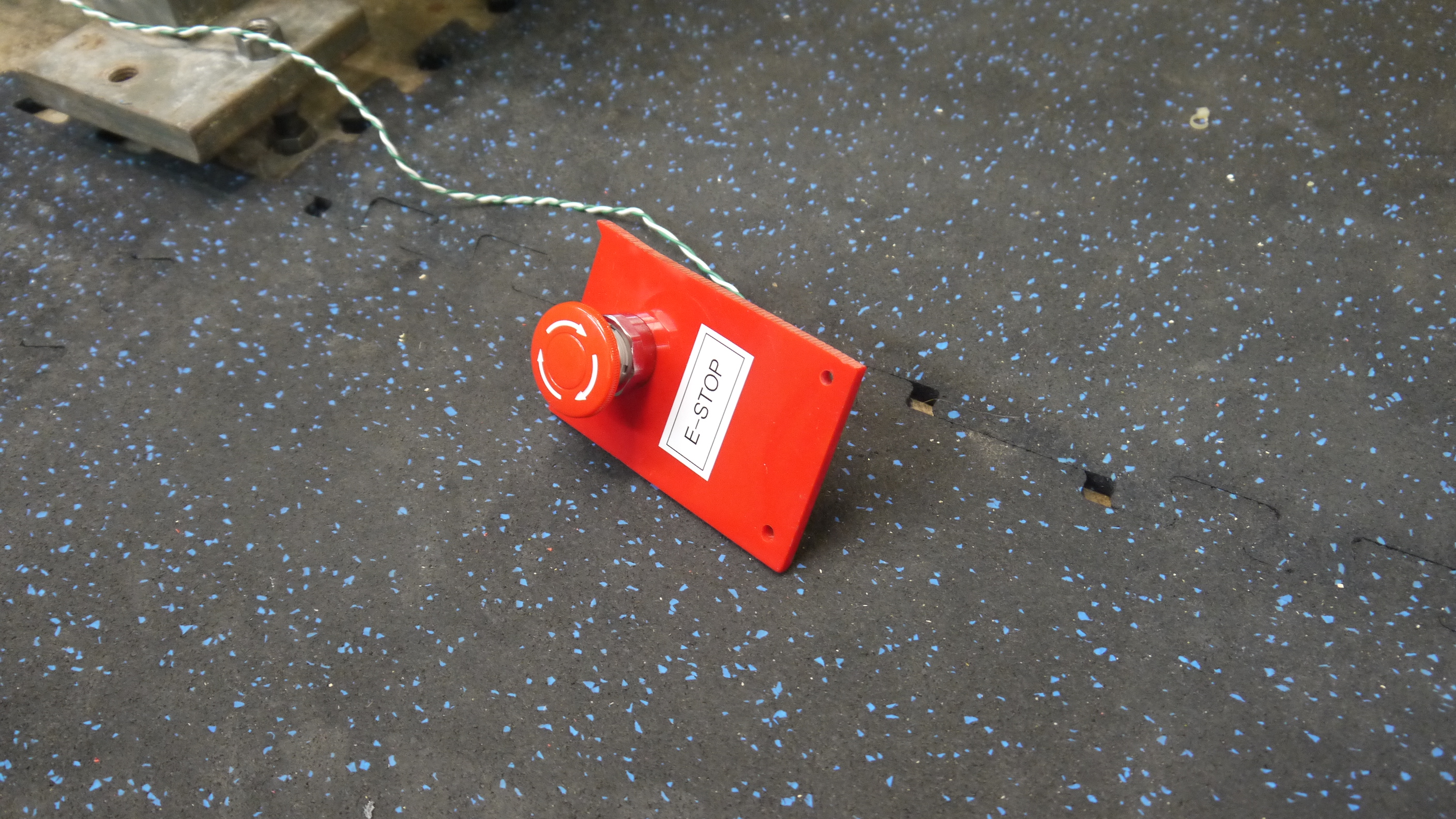
| Machine enable and E-STOP I opted for the cheaper version of the large industrial E-STOP buttons, these came from automation direct. There are two e-stop buttons on the machine, each connected in series such that if either becomes open-circuit, the main power contactor opens, the robot brakes enable and the servo drives 'regen' into the regen-absorber. The main E-STOP and ENABLE pushbuttons are available in the front of the robot, right under the lip of the table worksurface. |
 |
 |
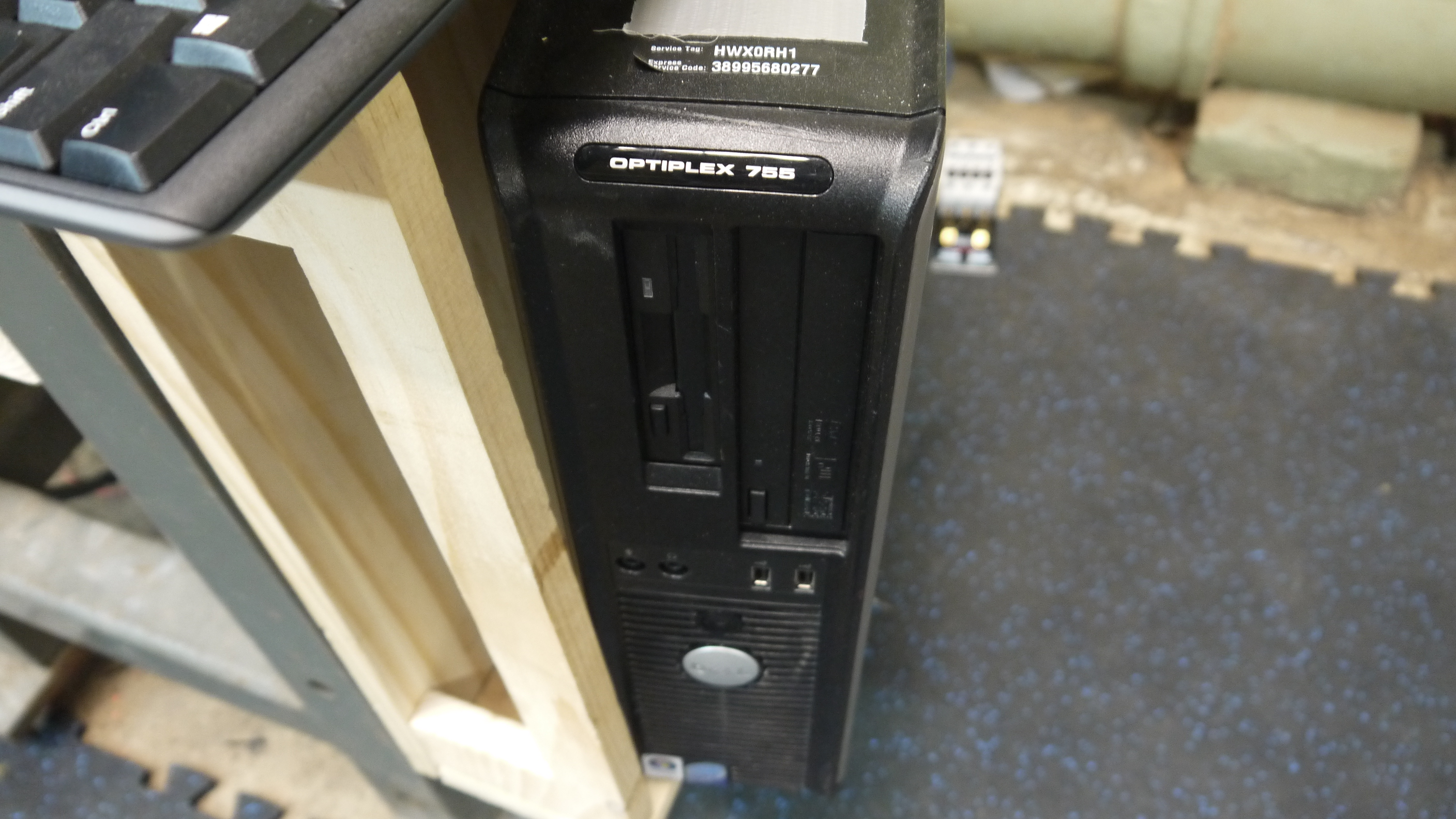
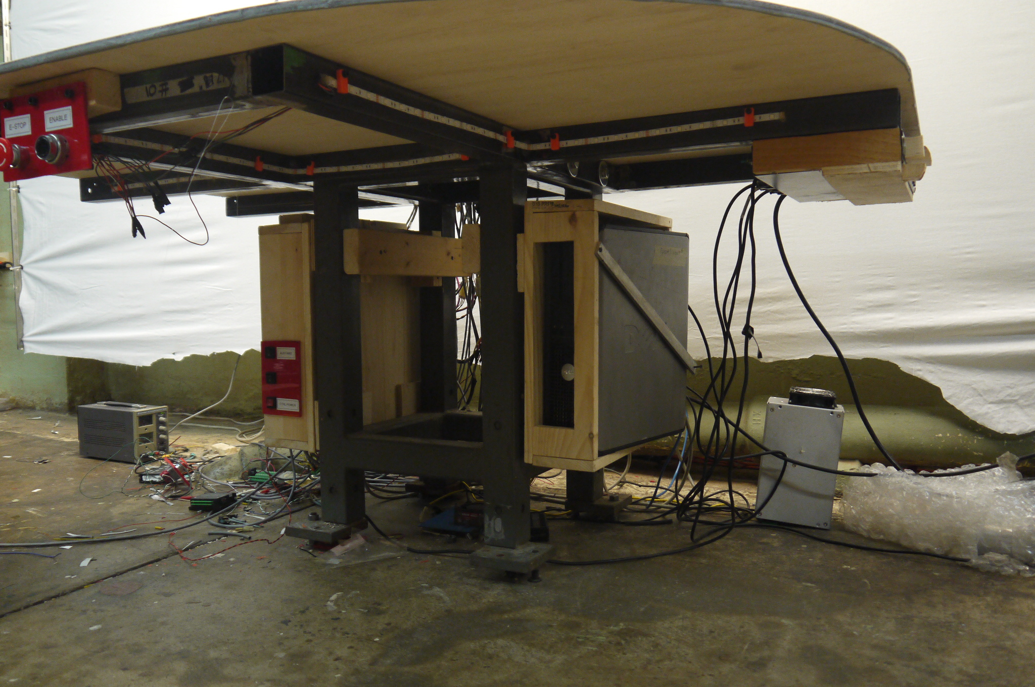
| Computer The host for the linux cnc install is an optiplex 755 [spec sheet] running a core 2 duo with 2GB of ram and an intel SSD. The machine itself was fairly bare, aside from the mesa card and a USB wireless keyboard adapter. I made wooden cases for both the electronics and the computer, nominally they both sit off the floor tied to the robot mount. I planned to make large cover panels to keep any dust and debris out, but, that seems like a future upgrade. |
 |
 |
| Safety Beam Brakes | ||
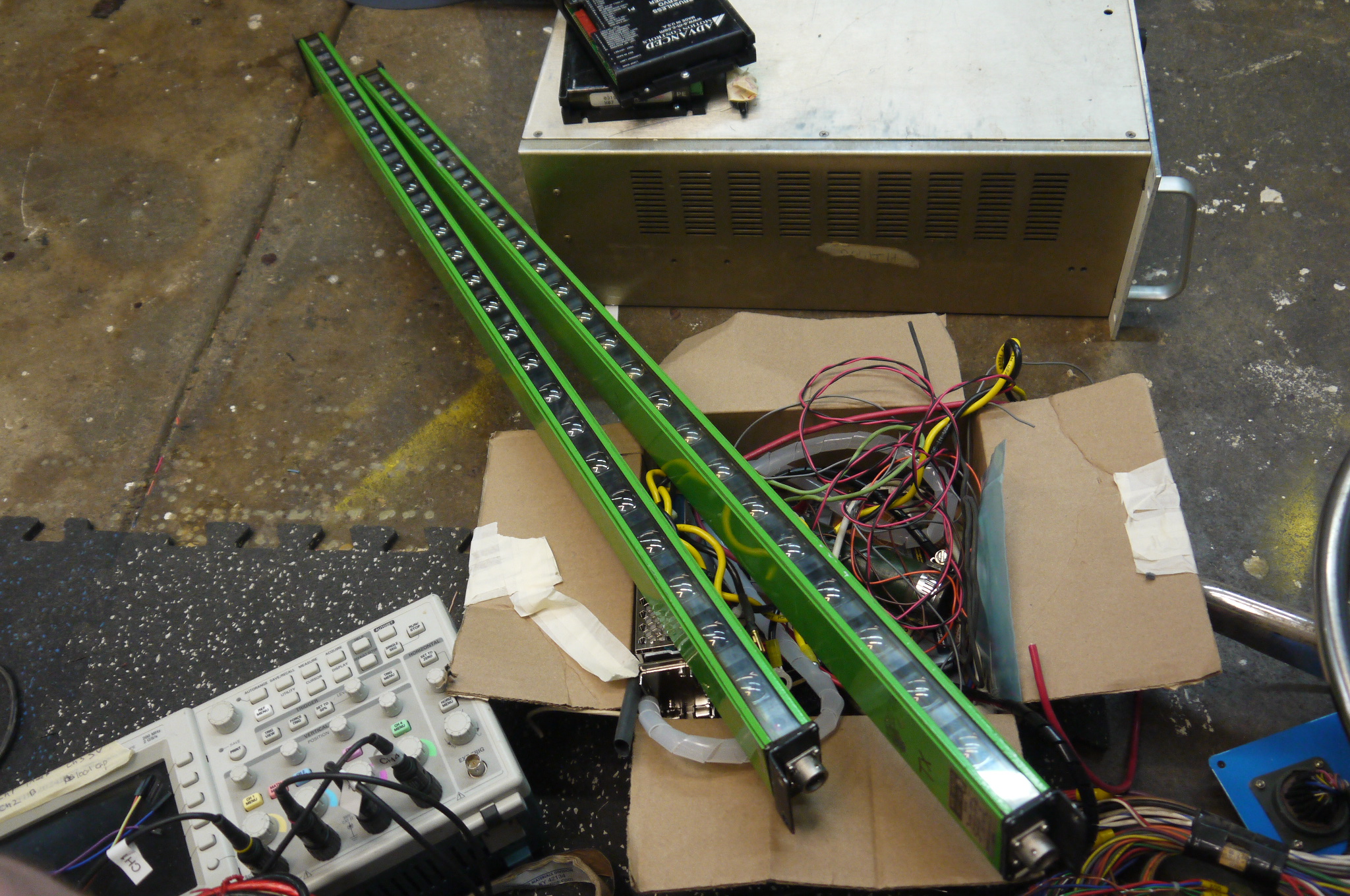
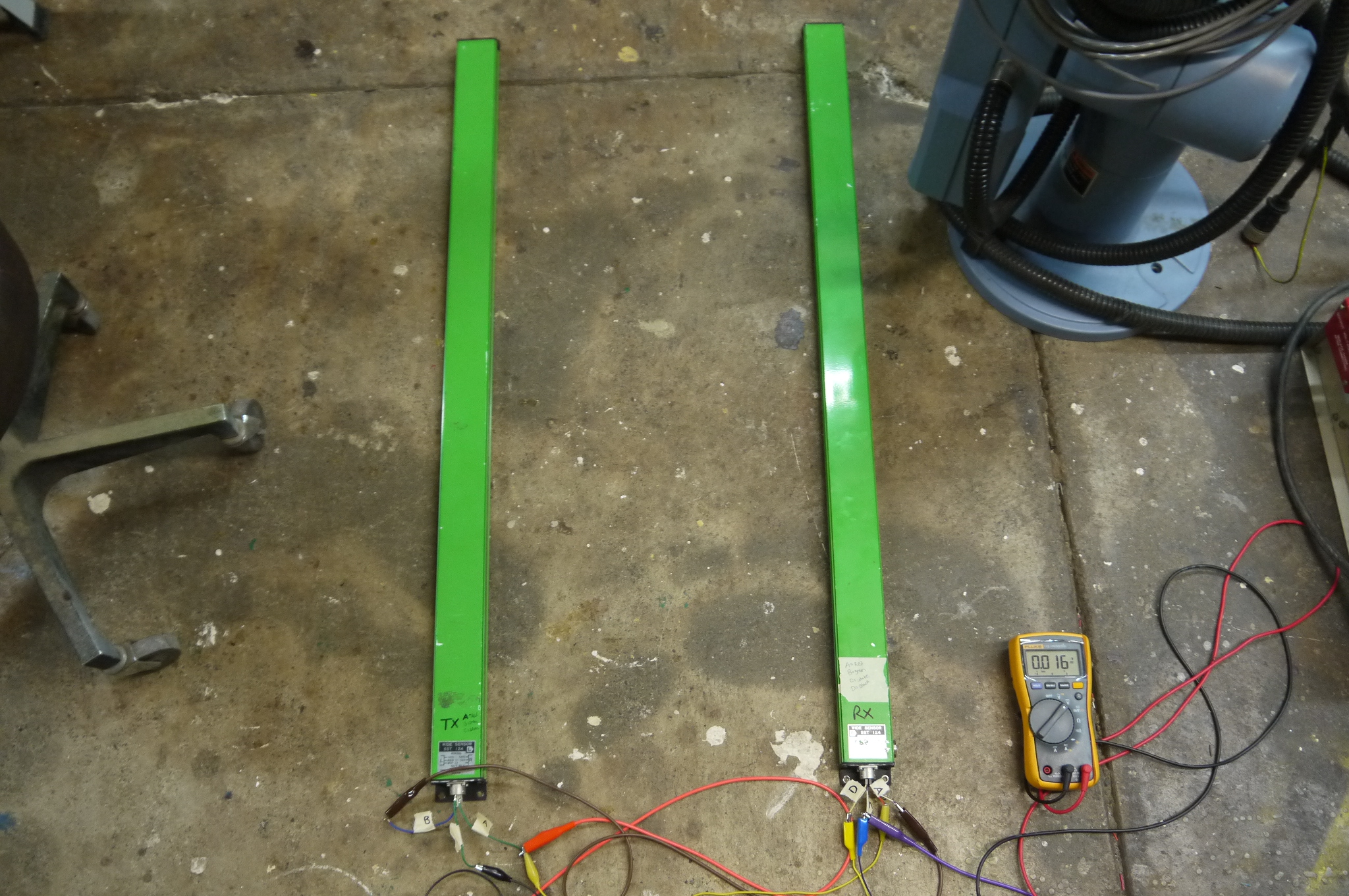
| To prevent accidentally running into the robot, a system of beambrakes were purchased (used). Initially my plan was to setup a bounding box with reflective standoffs about the bot. This was more difficult than i had planned to 'get right'. Shown right was my plan. | 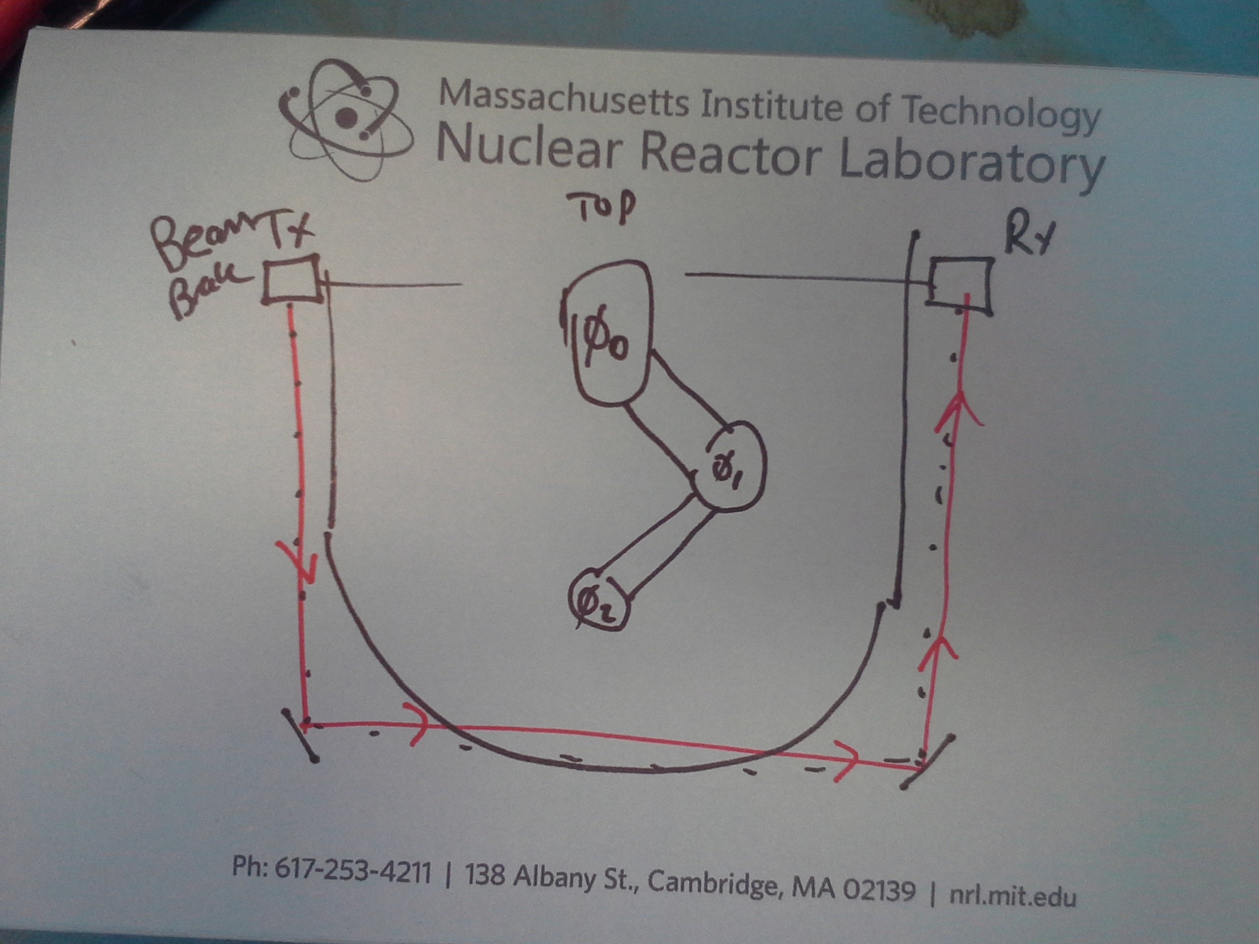 |
|
| Here are the light curtain transmitter and reciever sitting ~18" apart. Note, they work fairly well, I plotted to do a 'let them sit for an hour and check for spurious trips' and plan on doing that soon. Connecting the light curtain to the E-STOP loop would really require these to work well for extended periods of time. | 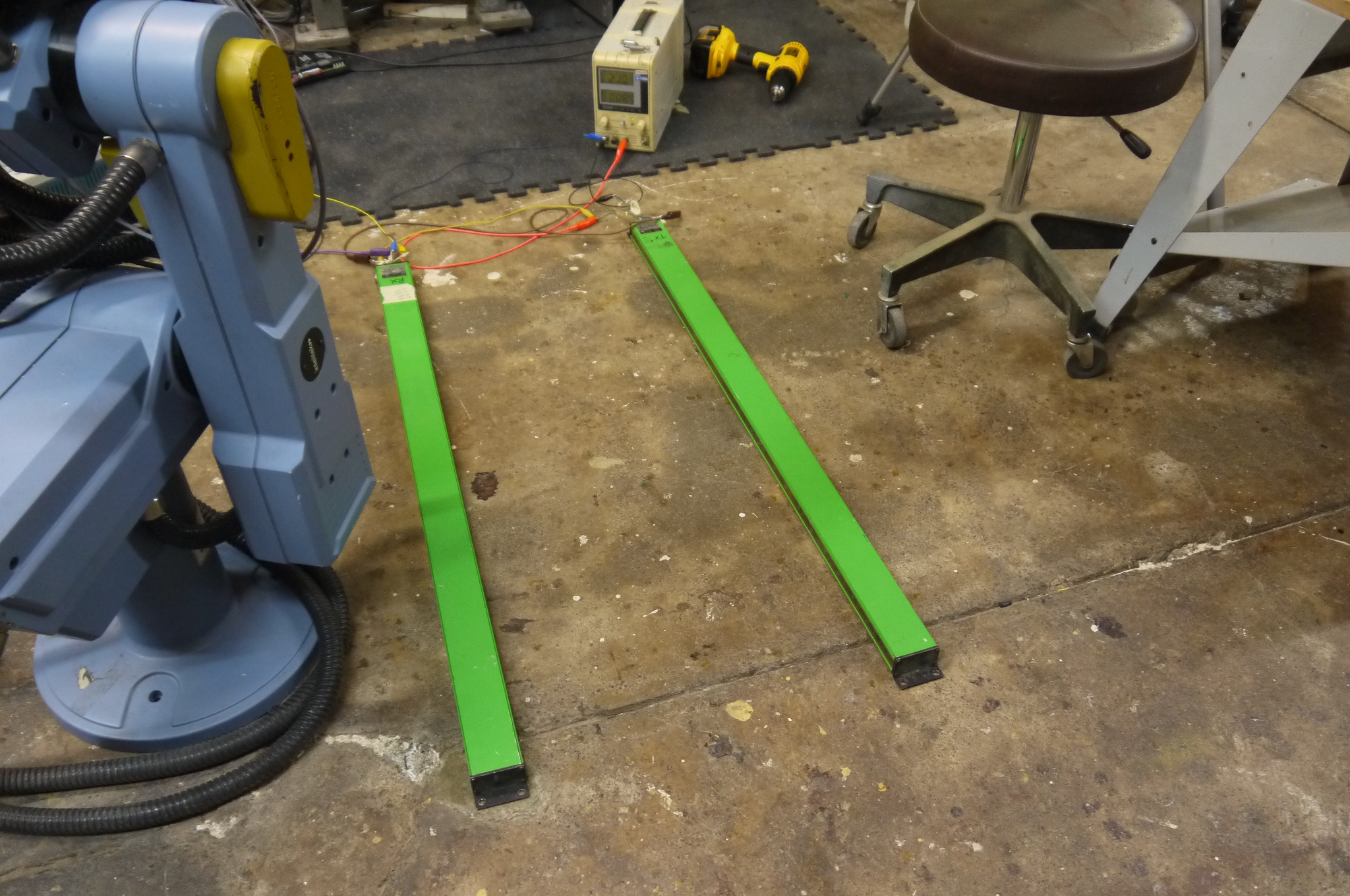 |
 |
| A more rigid mount will be used in the future to maintain a reliable beam-brake reflective setup for the whole robot. Just like the encoders, the beam-brake pinout was only figured out by opening the ends and mapping wire colors to pins. | 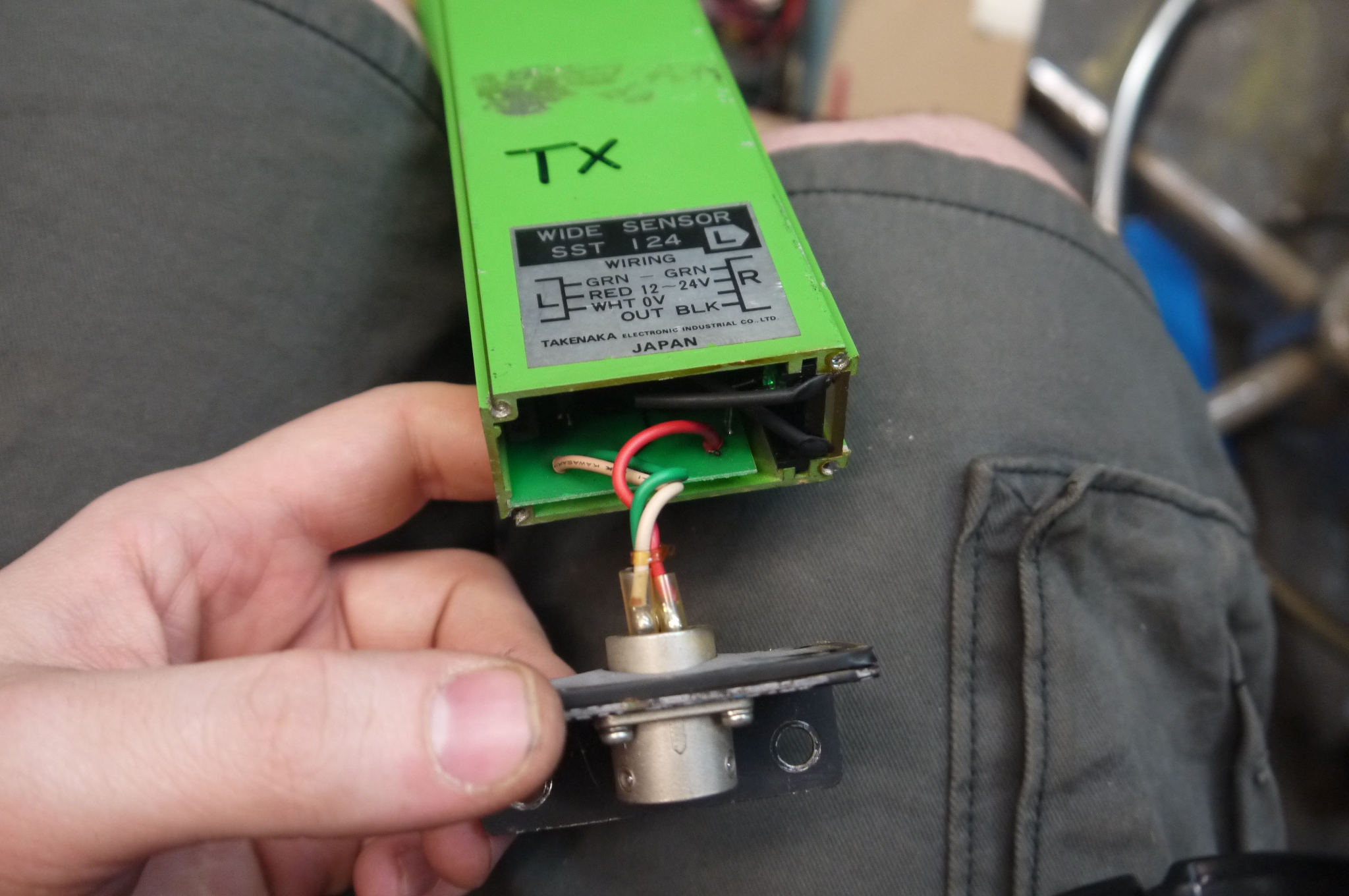 |
 |
| Z-Axis: Cad Ahoy | |
| Z-Axis
cad Ahoy As the bluebot did not have a Z-Axis, one needed to be fabricated. I was fortunate that a linear stage carcas was already happily waiting use, from the magical miters. The linear stage is a Parker 402006 lnms [some data from parker here]. It uses a 3/16 size shaft. I opted for a lovejoy style coupling between the NEMA23 stepper and the parker z-axis shaft. I used a 3/16" diameter mcmaster-carr [6408K912] coupling on the parker z-axis side and a [6408K913] on the Stepper motor side. A rubber spider [6408K913] was used to complete the coupling. The CAD itself is broken up into two parts, the 'hold the parker linear stage on the robot, perpedicularrly with the center of the axis in the center of the Theta 2 axis' and the 'add a long arm that reaches through the robot' Want the cad? check out the downloads section! |
INTERACTIVE RENDER (spin with mouse) |
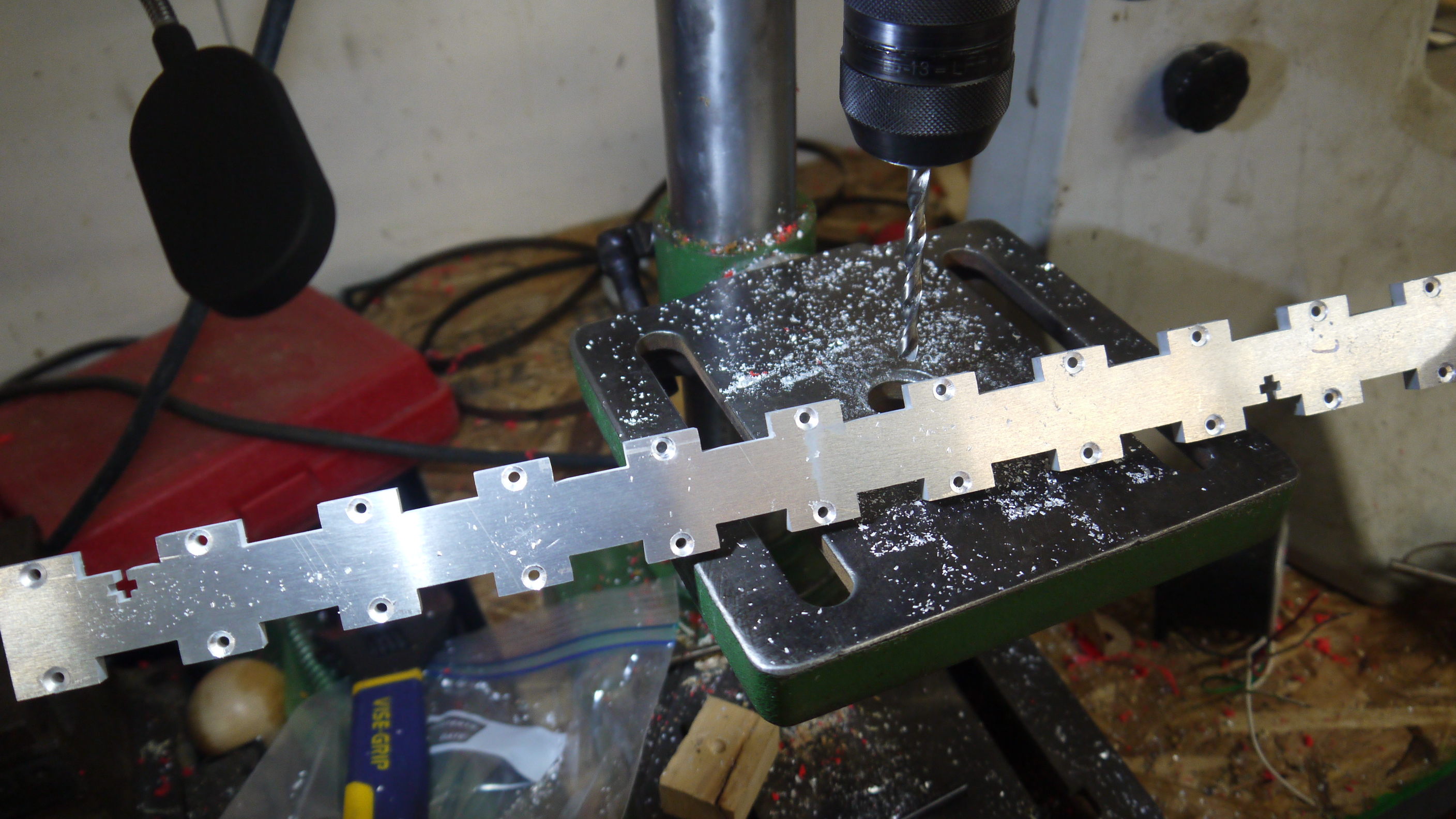
| The Z-Axis design was aimed at 'quick to assemble' with minimum post machining. As such, plate aluminum was used and waterjet to use captured square nuts and square interlocking peg-and-hole joints. This is nominally the 'T-NUT' method [link]. Using a waterjet to cut the parts resulted in quite reasonable perpendicular support arms. The Theta-2 mount attaches to the rotary axis of the blue robot. The Parker linear actuator mates with eight M5 hex machine screws. The coplanar support plate then attaches with captured nuts and bolts to the support arms and theta 2 mount. The structure was quite rigid given the extent of the support arm geometry. | 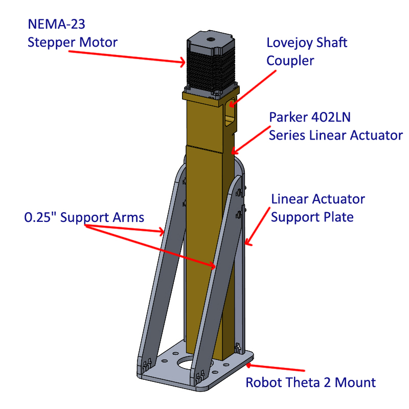 |
| The Z-Axis arm reaches from the top of the linear actuator, through the center of theta-2 and down to a mating tool post interface. To keep the structure from twisting and bending a lot of hardware was used to interface the actuator arms and support plate. An interface plate to the linear actuator constrains the arms and ensures that they maintain perpendicular. One of the design choices here is to allow the actual actuator arm to remain hollow. This allows for cabling to run through the axis for running powered tool posts. |  |
| I used a waterjet to cut out the parts from scrap 1/4" 6061 aluminum plate. This is, sped up by a significant factor, but its really fun to watch. A 60kpsi jet of water (mixed with garnet abrasive) is sprayed through a nozzle and into the plate, this cuts a thin beam through the plate and leaves you with the completed cutouts. |  |
| Z-Axis Construction | ||
| The waterjet parts came out great. I opted for countersunk torx for the 4-40 screws to leave as few exposed things on the z-axis arm. Initially i purchased a countersink bit, but, I opted for a 6 flute one and it immediately clogged with aluminum. A drill bit did a reasonable job as a replacement. |  |
 |
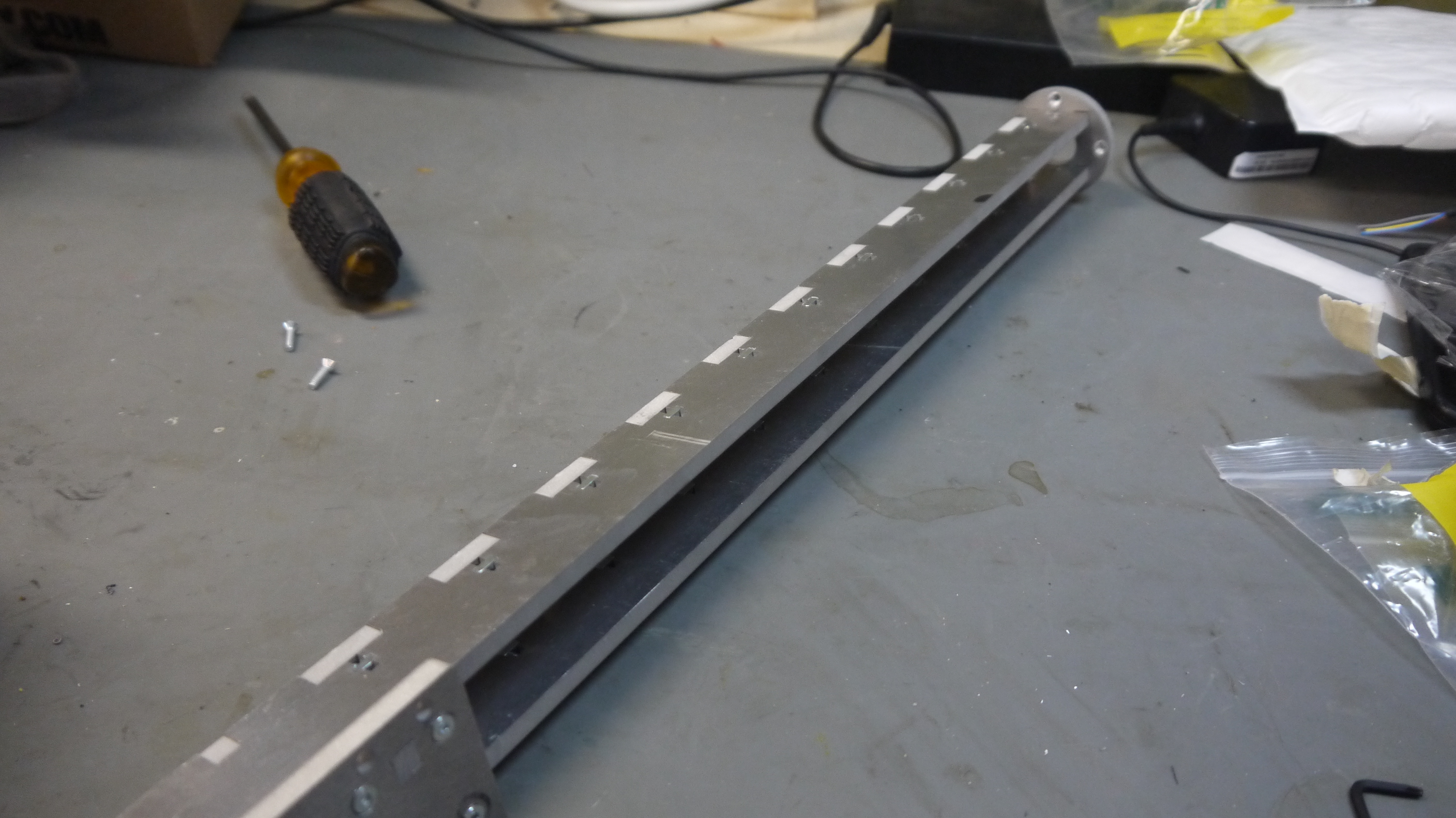
| The arm went together fairly quickly and felt rather rigid. As shown the tabs fit together quite well. The interface plate is shown on the bottom left corner. | 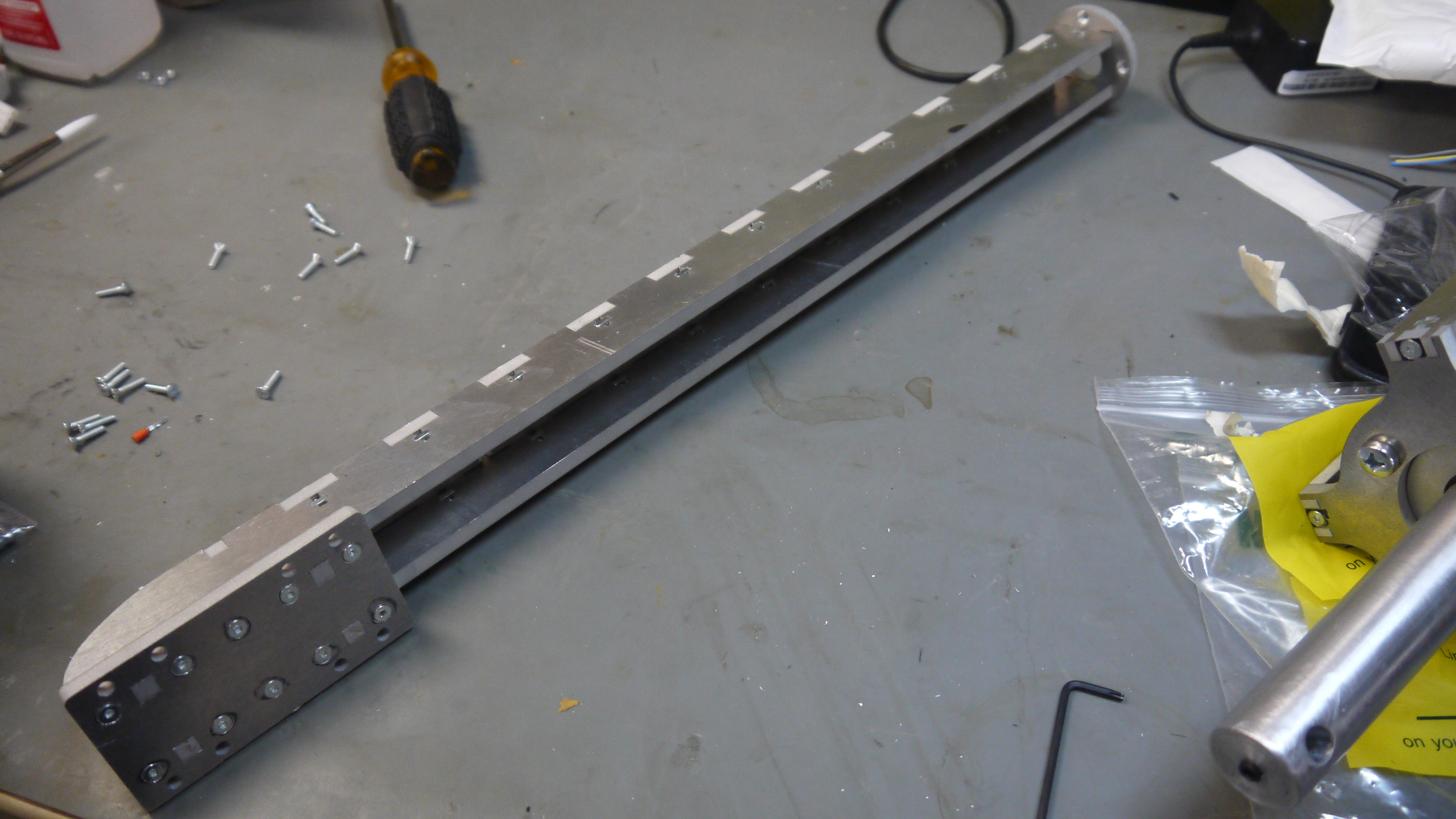 |
 |
| Bench test of Z-Axis | 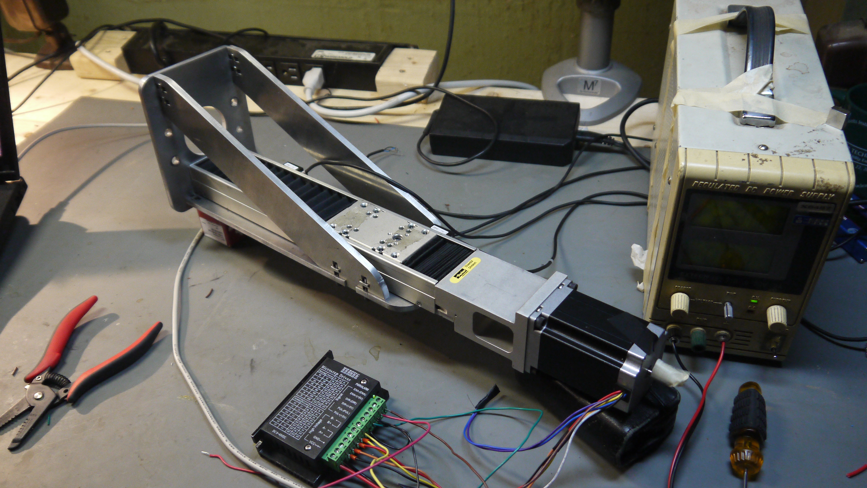 |
|
| Z-Axis actuator and arm attached to the robot | 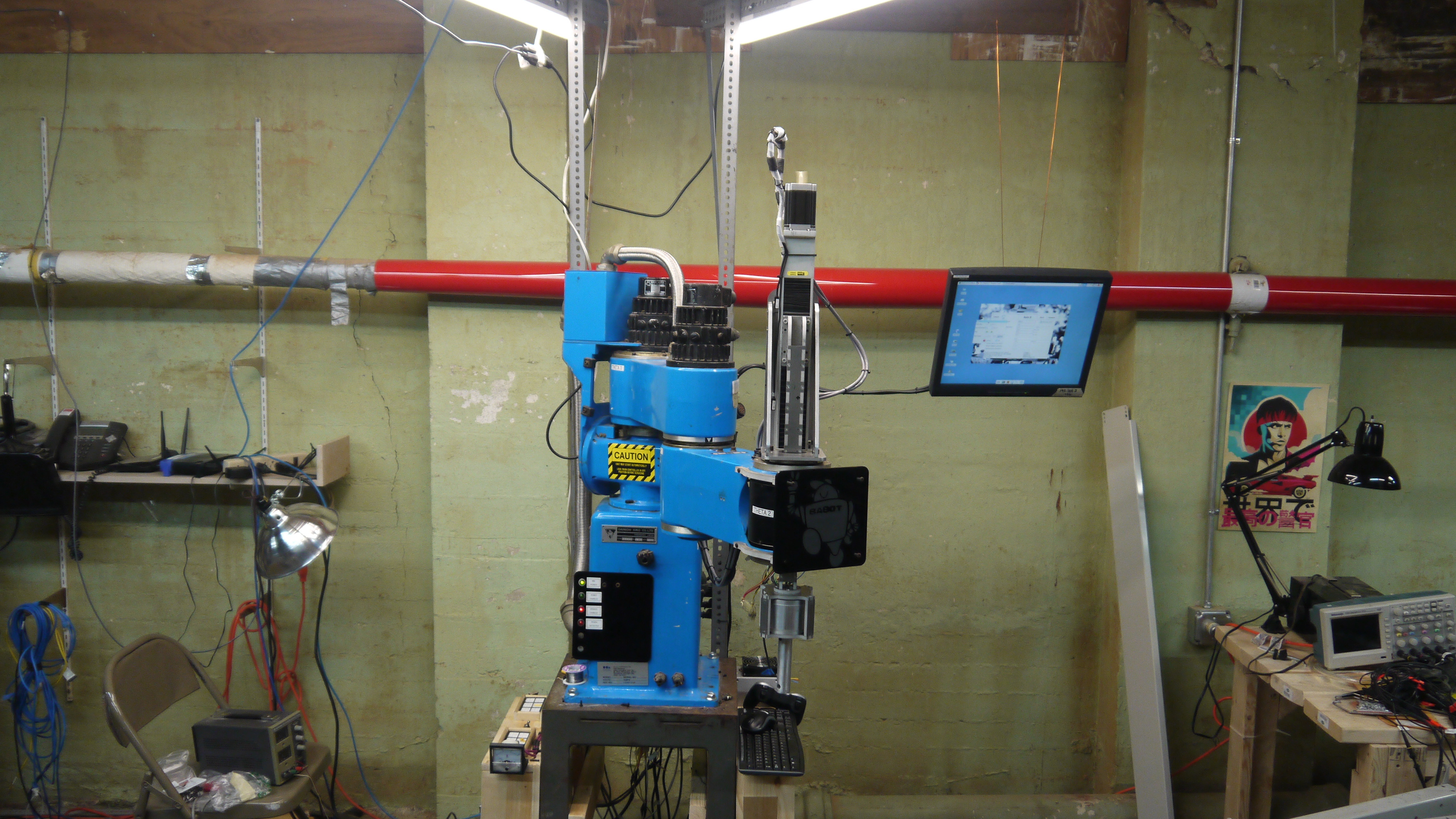 |
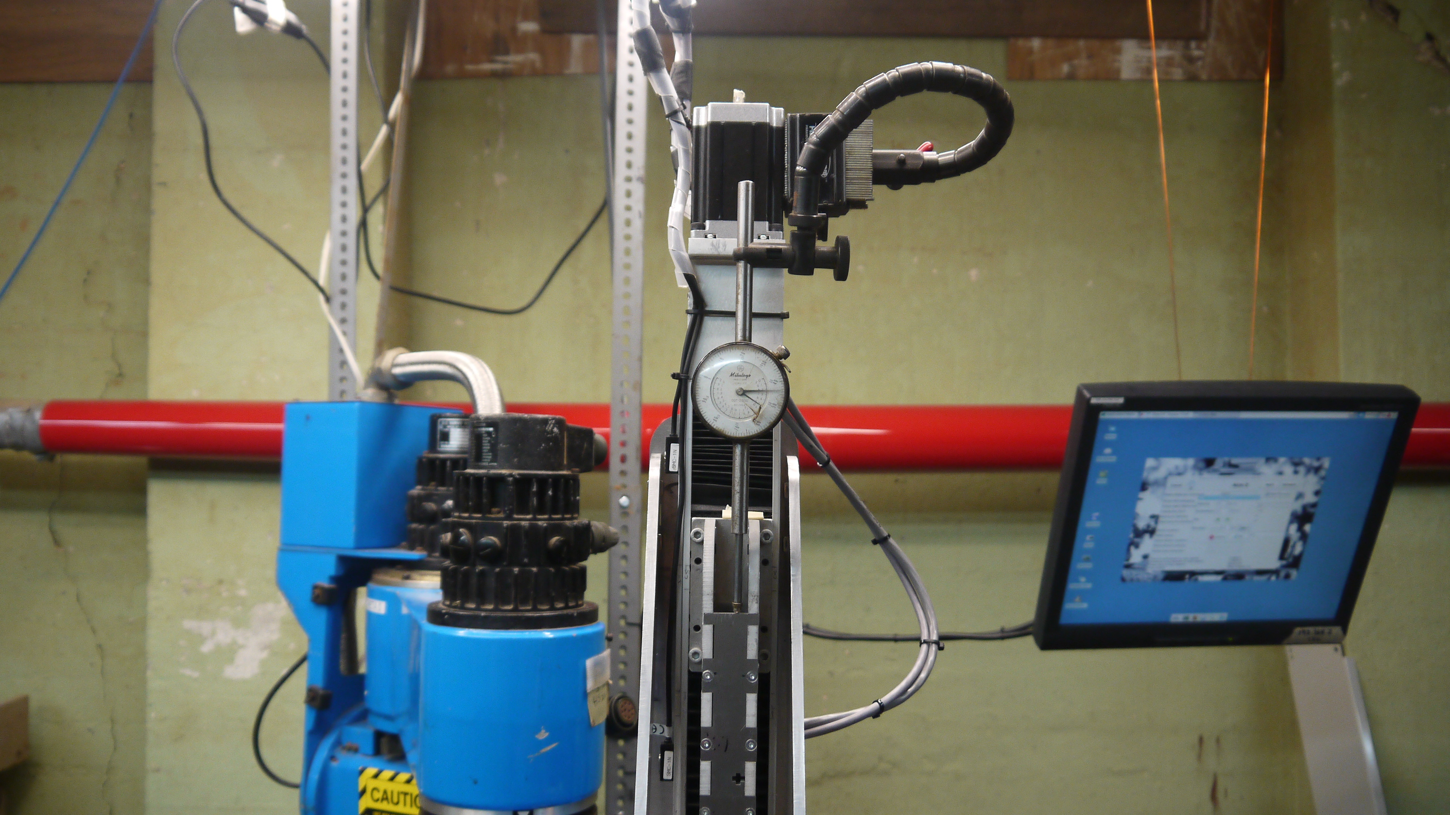 |
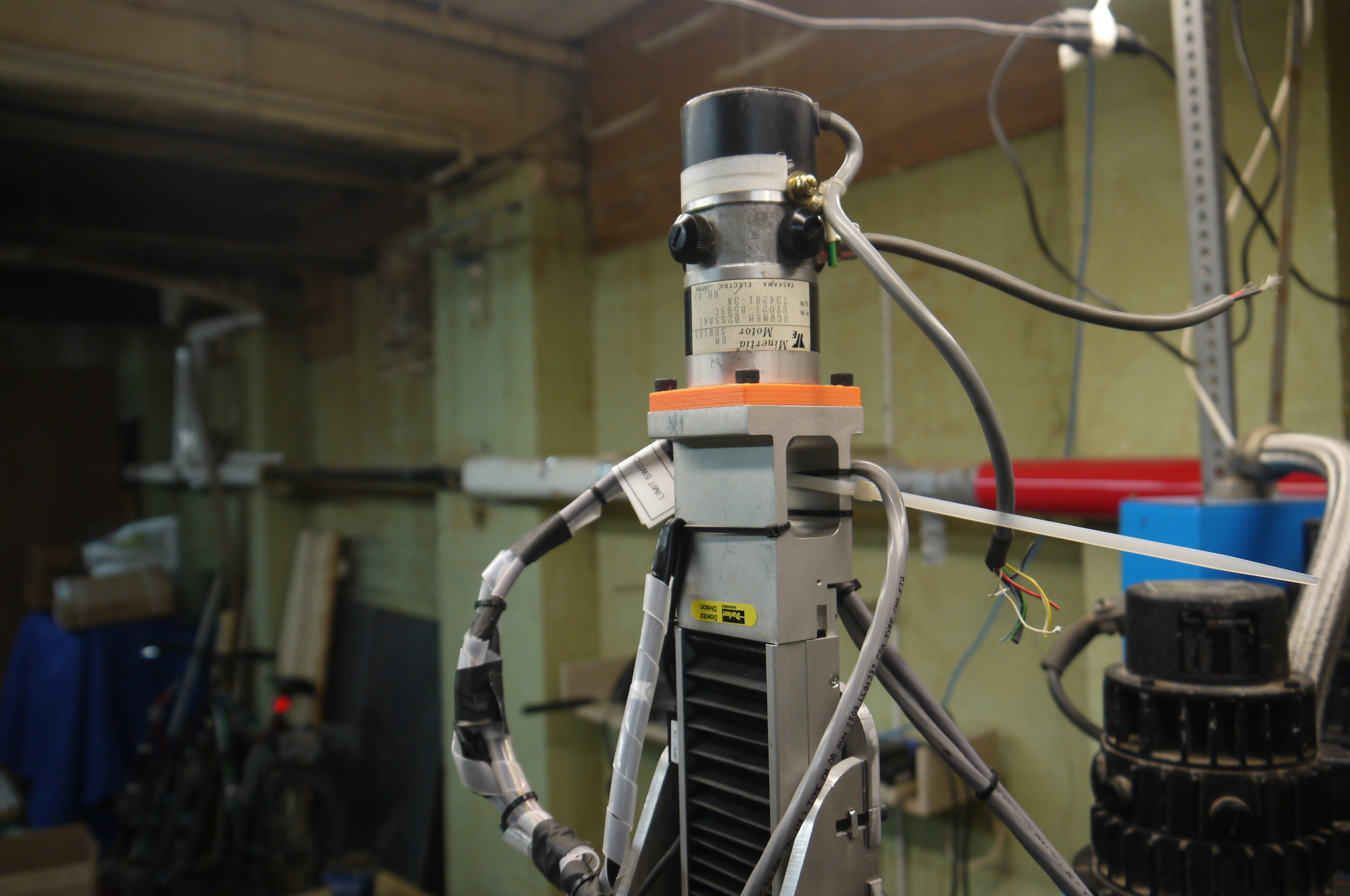
| aaaaand,
i switched over to a brushed dc servo And after all that stepper goodness, I switched to brush-dc servo + encoder. I was reasonably conerned that a missed couple steps over the course of a 5 hour long job would be quite the bother. This particular motor was gifted from a IBM 7575 that was parted by the ever excellent mcmaster. I made a quick 'nema-23' adapter for the motor and everything came together smoothly. Having encoder feedback all the way back to the computer closes the loop and prevents poor positioning from fouling up an otherwise functioning robot. |
 |
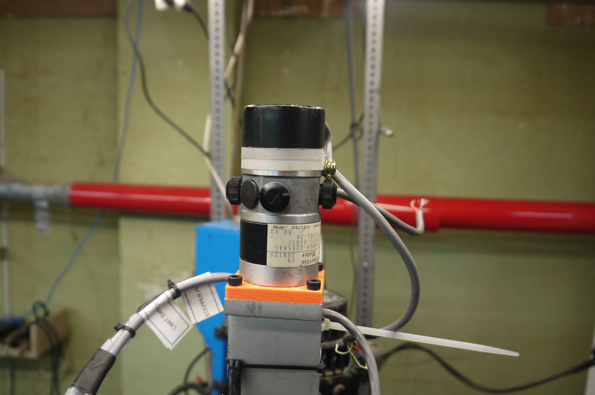 |
| Cad
model of motor and 3d printed adapter For all of you out there with this bizzare 80's dc brush servo, that also want to convert to nema 23 duty, here's the cad model for the adapter. Check it out in the downloads section. |
 |
 |
| Testing the Z-Axis for the first time (stepper) | |
| To verify the stepper, leadscrew and stepper driver setup would work well, I did a quick bench test. This consisted of a bench power supply (current limited), an Arduino uno and the stepper driver. I wrote a quick test script that toggled the direction line and did a quick, constant velocity up-down motion. Everything was behaving so, time to integrate on the bot. |
| Linux CNC: Initial Futzing with MESA and Encoders | |
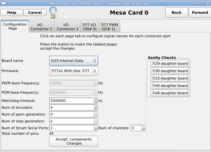 First steps: First steps:This was my first forray into linux cnc with MESA interface cards, so I went for simple configurations initially. From the linux cnc desktop i selectd linuxcnc -> PNCNC config. For this build I was using a 6I25 (directly compatible with 5I25) pci card and a single 7I77 breakout board. If this is your hardware configuration, then choose 'BOARD NAME' = 5i25 and 'FIRMWARE' = 7I77x2 with One 7I77. The encoder inputs are selectable up to 6, for this project I was planning on using four (theta 0, theta 1, theta 2, z-axis) |
|
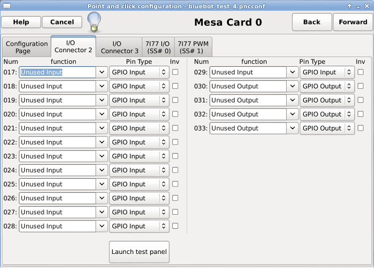 For I/O Connector 2 tab,
I had all the inputs and outputs set as un-used. Where
is I/O Connector 2? its actually on the PCI card
itself, which was a bit of a ways away from the
control platform. Note 'Launch test panel' doesnt do
anything, from my observations. I/O connector 2, 3 are
settings for the FPGA (6I25 / 5I25) only, this is not
configuring the breakout board (7I77). For I/O Connector 2 tab,
I had all the inputs and outputs set as un-used. Where
is I/O Connector 2? its actually on the PCI card
itself, which was a bit of a ways away from the
control platform. Note 'Launch test panel' doesnt do
anything, from my observations. I/O connector 2, 3 are
settings for the FPGA (6I25 / 5I25) only, this is not
configuring the breakout board (7I77). |
|
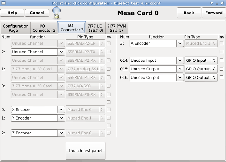 For I/O Connector 3 tab,
we setup the encoders. Note as there's only one 7I77
connected to the coms link, '2' is selected as Unused
Channel. That connection can be used to set up
communications with external breakout cards. Shown
here is the X, Y, Z, A encoders selected on the
encoder mux's. I left the Z axis encoder tied in here
in case i wanted to use it at a later time for a
brushed Z Axis (hint, i ended up switching the Z axis
to brushed dc servo) For I/O Connector 3 tab,
we setup the encoders. Note as there's only one 7I77
connected to the coms link, '2' is selected as Unused
Channel. That connection can be used to set up
communications with external breakout cards. Shown
here is the X, Y, Z, A encoders selected on the
encoder mux's. I left the Z axis encoder tied in here
in case i wanted to use it at a later time for a
brushed Z Axis (hint, i ended up switching the Z axis
to brushed dc servo) |
|
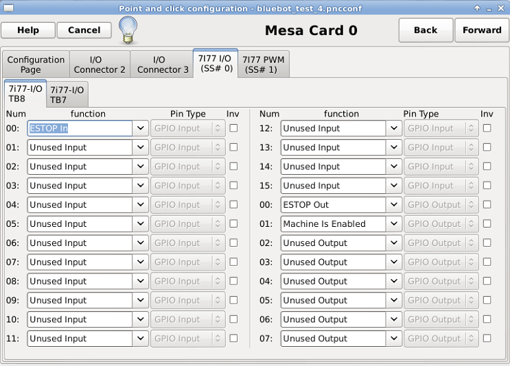 Next
up is the 7I77 configuration Next
up is the 7I77 configurationAs this was the first time I'm using the mesa card as an input/output driver, I opted for extremely basic. One input and two outputs. The two outputs were routed to 24v current limited LED's and fed directly from the outputs of the MESA. The input was routed through a toggle switch fed from the 24v rail. This toggle switch would simulate an ESTOP pushbutton. |
|
 7I77 configuration
Continued 7I77 configuration
ContinuedAll set to un-used inputs/outputs for startup testing. Later on in the build i used a few of these for limit switches and user interface buttons. |
|
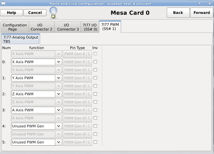 Finally
the analog outputs for this application are routed. The
analog outputs (PWM) are driven from the 7I77 PWM
tab. I am using four of the six available
configurations. Finally
the analog outputs for this application are routed. The
analog outputs (PWM) are driven from the 7I77 PWM
tab. I am using four of the six available
configurations. |
|
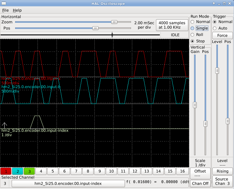 Firing up HAL SCOPE Firing up HAL SCOPEHal-scope streams data from the mesa card to the host pc and displays it as an oscilloscope plot. Its quite useful for verifying the inputs are actually working as inputs. In this case I have [5i25 (mesa fpga card) encoder 00 input index] or encoder 0 index on channel 3, and encoder 0 input A / B on channel 1 / 2. It does appear 'wonky' the encoder ticks are a bit sporadic, but also note that this is only sampled at 1khz. This is mostly useful for verifying the hardware is present, a normal oscilloscope itself is useful for verifying noise on channels and logic levels. This was recorded while I was moving the arm manually, the encoders themselves dont do much when the robot isnt moving :] |
|
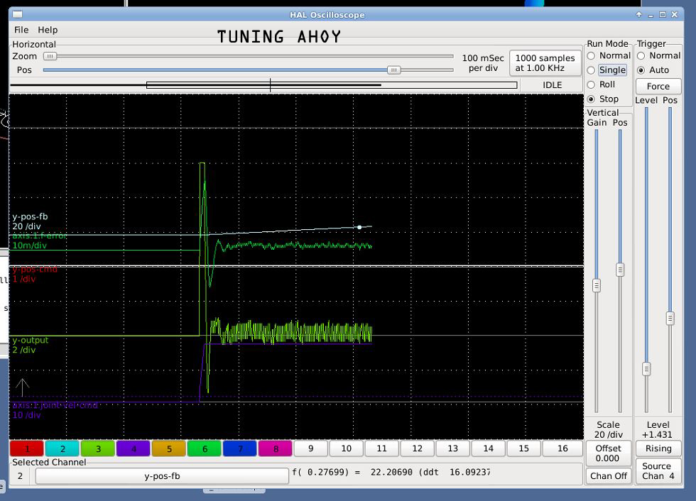 Halscope
is also wonderfully useful for tuning the axes PID and
feed forward constants, these are actually available on
the fly (so you do not need to constantly close-open
linuxcnc. Shown is the y (theta 1) axis feedback and
output for a velocity capped trajectory. This is really
a fantastic tool, having visibility into velocity
acceleration and position loops in relation to their
target values makes tuning less of a guessing game. The
ever fantastic Peter came to aide in getting this
robot under control, we spent a solid 2 evenings putzing
with getting the home sequence right and keeping the
oscilations down. Halscope
is also wonderfully useful for tuning the axes PID and
feed forward constants, these are actually available on
the fly (so you do not need to constantly close-open
linuxcnc. Shown is the y (theta 1) axis feedback and
output for a velocity capped trajectory. This is really
a fantastic tool, having visibility into velocity
acceleration and position loops in relation to their
target values makes tuning less of a guessing game. The
ever fantastic Peter came to aide in getting this
robot under control, we spent a solid 2 evenings putzing
with getting the home sequence right and keeping the
oscilations down. |
|
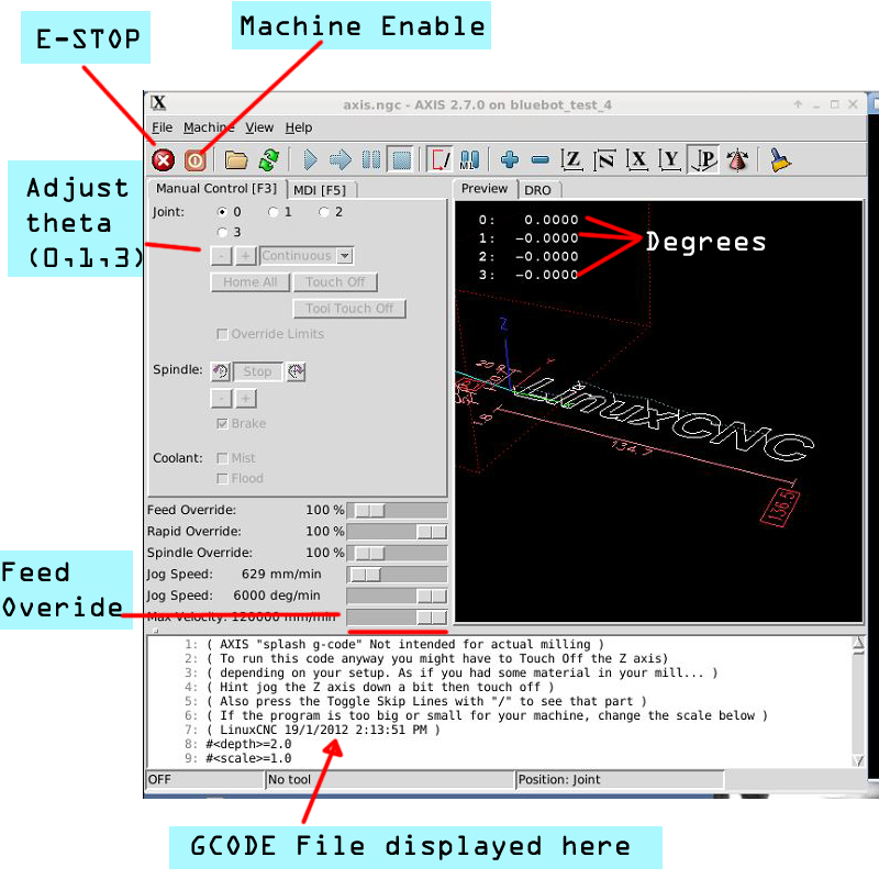 After
the configuration is up and running the main screen
looks like this. E-STOP and Machine Enable are the first
big players here, ESTOP as an output kills the robot
power while machine enable allows the outputs. In the
manual control tab, in continuous mode, 0,1 sweep theta
0 or theta 1 back and forth, while '2' actuates the Z
axis. Feed Override is incredibly useful, as it allows
for a realtime adjustment of the present job. Painting
taking a long time, bump up the feed override :] After
the configuration is up and running the main screen
looks like this. E-STOP and Machine Enable are the first
big players here, ESTOP as an output kills the robot
power while machine enable allows the outputs. In the
manual control tab, in continuous mode, 0,1 sweep theta
0 or theta 1 back and forth, while '2' actuates the Z
axis. Feed Override is incredibly useful, as it allows
for a realtime adjustment of the present job. Painting
taking a long time, bump up the feed override :] |
|
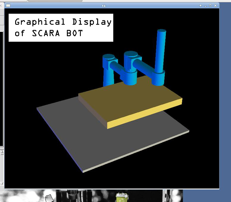 If
you're running a scara based robot, take a gander at the
following, the TK *does* allow for tweaking of colors.
This whole robot reacts in real-time based on encoder
feedback. When the robot servodrives are disabled, you
can move the robot around and the model tracks 1:1 with
the motions. This was mighty helpful when debugging
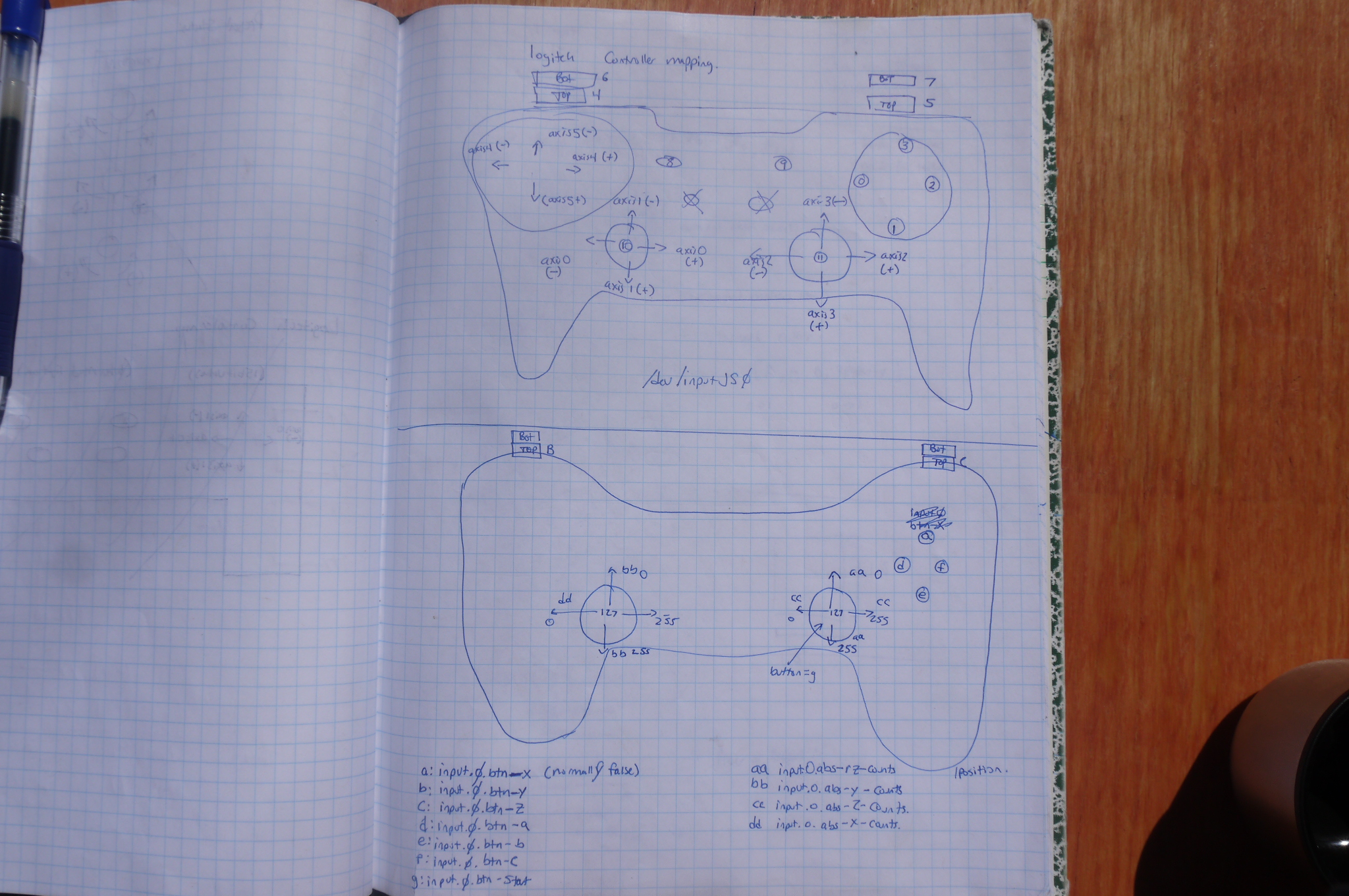
scaling factors using the logitec game controller. If
you're running a scara based robot, take a gander at the
following, the TK *does* allow for tweaking of colors.
This whole robot reacts in real-time based on encoder
feedback. When the robot servodrives are disabled, you
can move the robot around and the model tracks 1:1 with
the motions. This was mighty helpful when debugging
scaling factors using the logitec game controller. |
|
| Linuxcnc Configuration files Bluebot configuration ini file [link] Bluebot configuration hal file [link] M101 [link] M102 [link] Zip of whole directory [link] |
| Lasercutter and BABOT logo | |
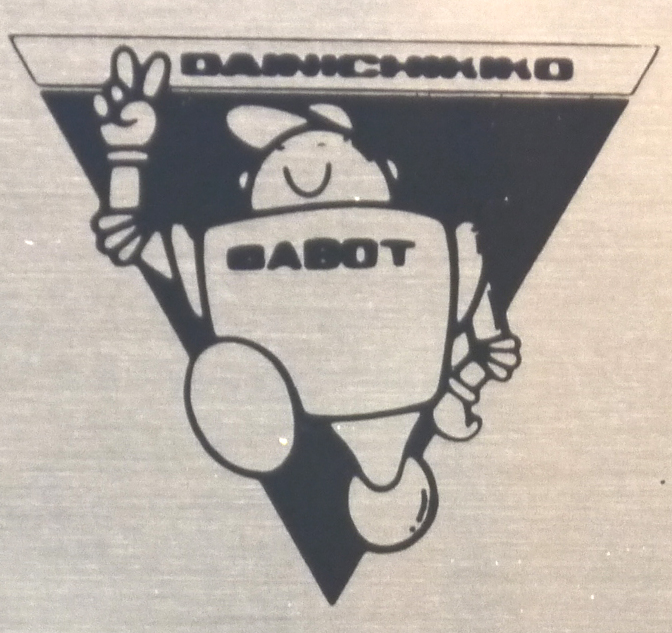
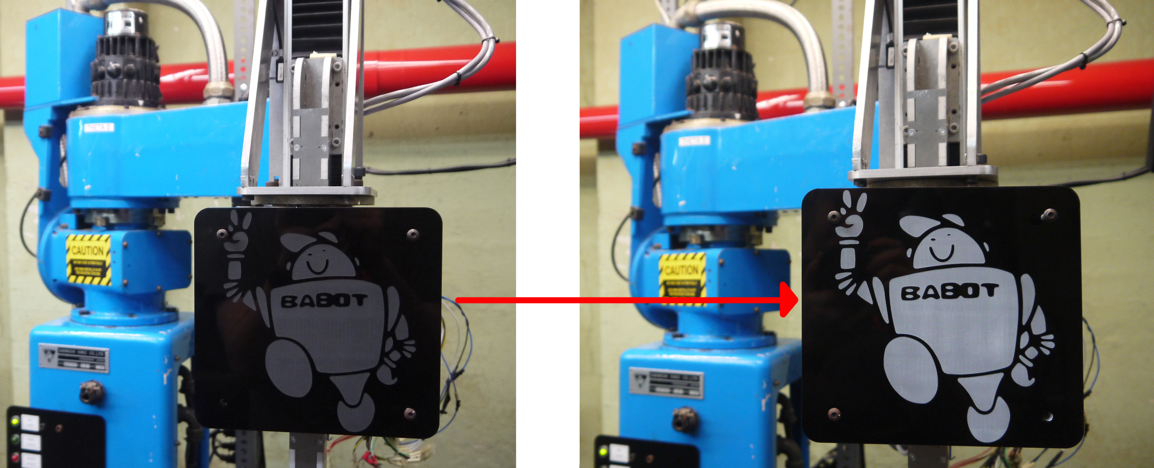
| The previous owner made a flat front-face mount for bluebot, with a wooden mount sitting on the front. I saw the opportunity to give bluebot a smiley face [ahem ahem]. After toying with some settings I found a lasercut setting that etched the black acrylic and left a deep contrast. Shown is a timelapse of the ratser on an epilog 120w monsterbeast. Thanks again to the mighty Coby for the illustrator sketch of the BABOT logo. |  |
Adding some paint to the etched
areas: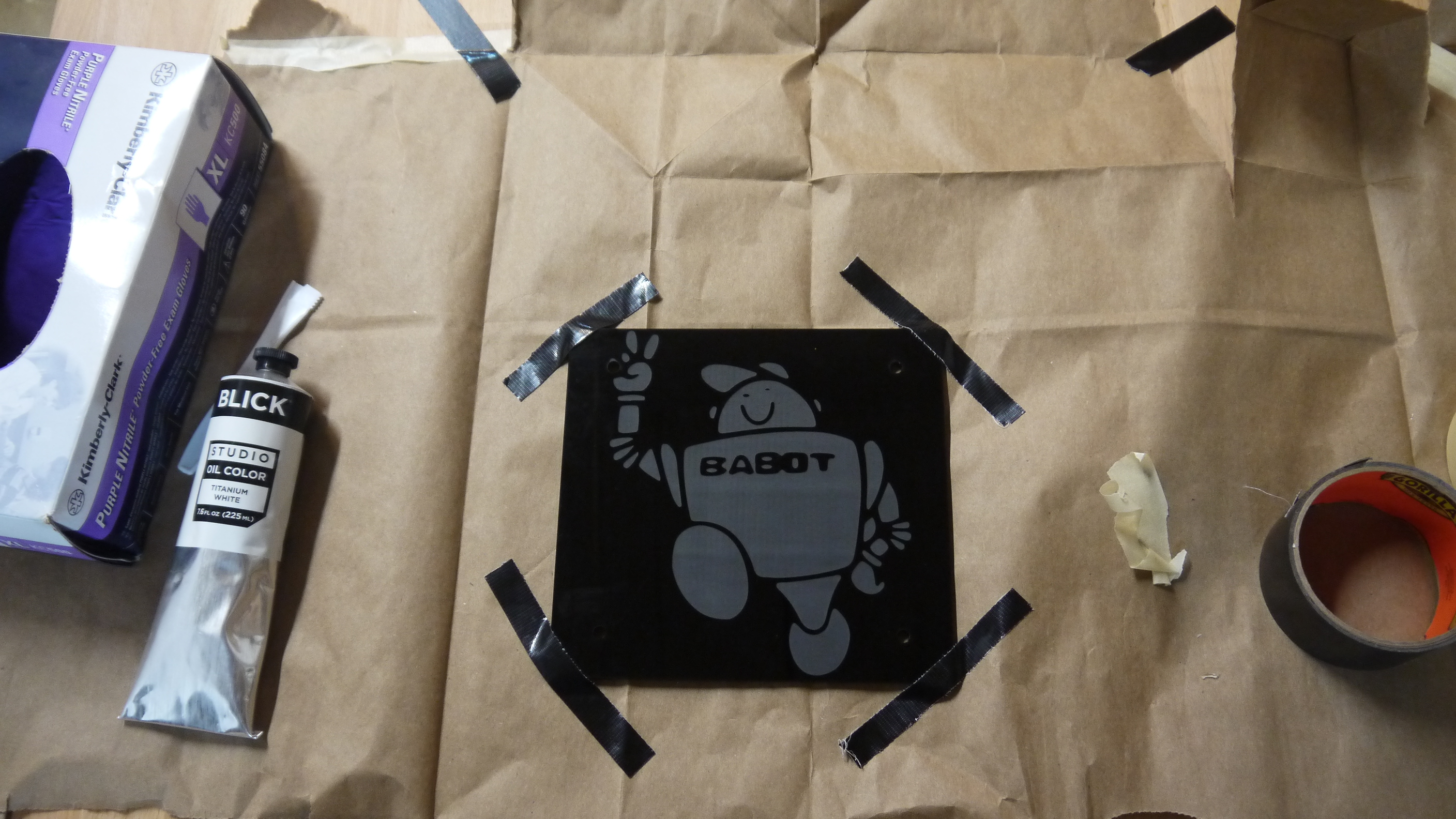 To paint 'babot' in, I used titanium white acyrlic paint and smeared it on with a nitrile glove, my logic was that the acrylic paint would not stick |
 |
| Overhead lighting of great glory and a backdrop. |
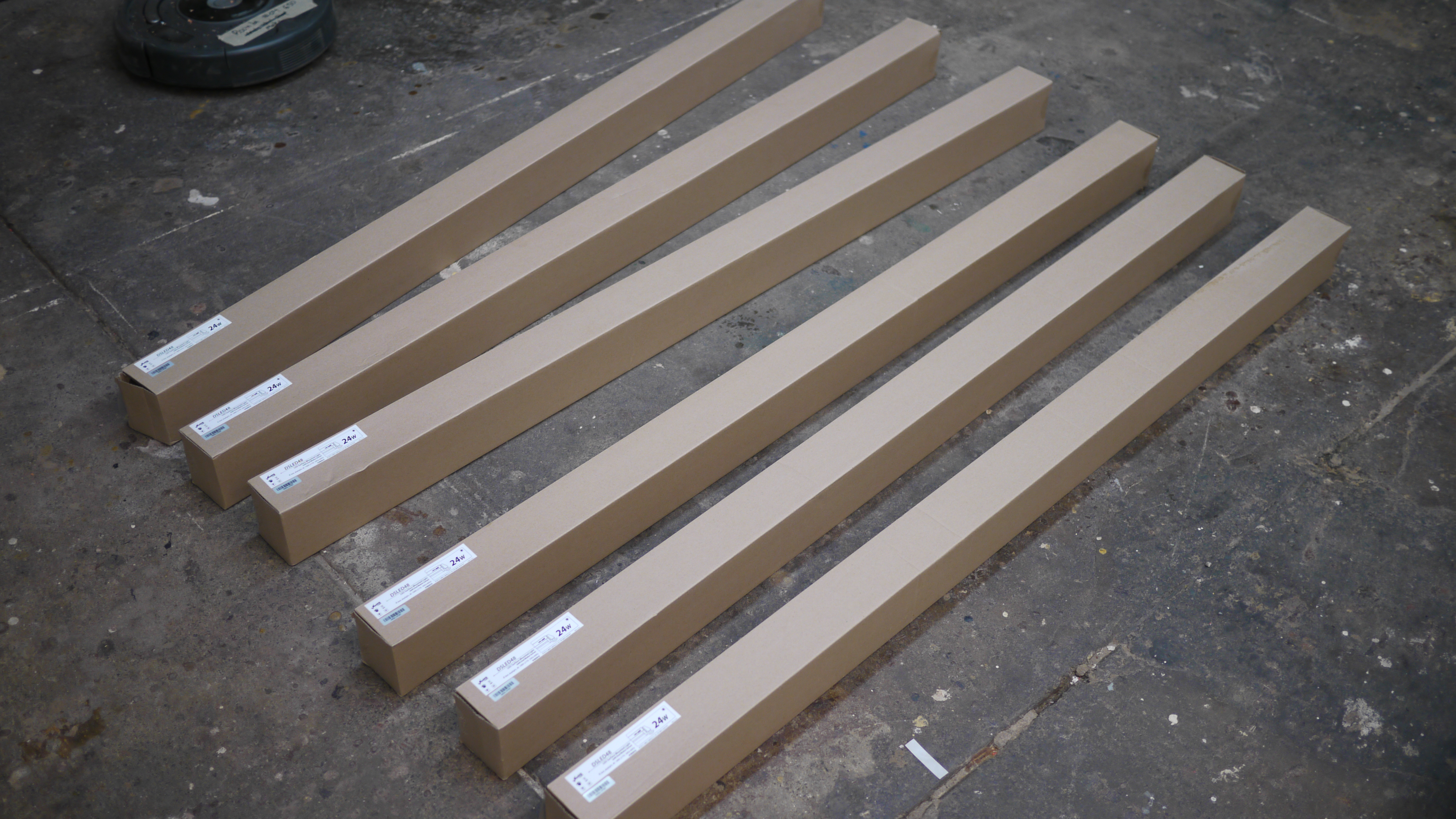 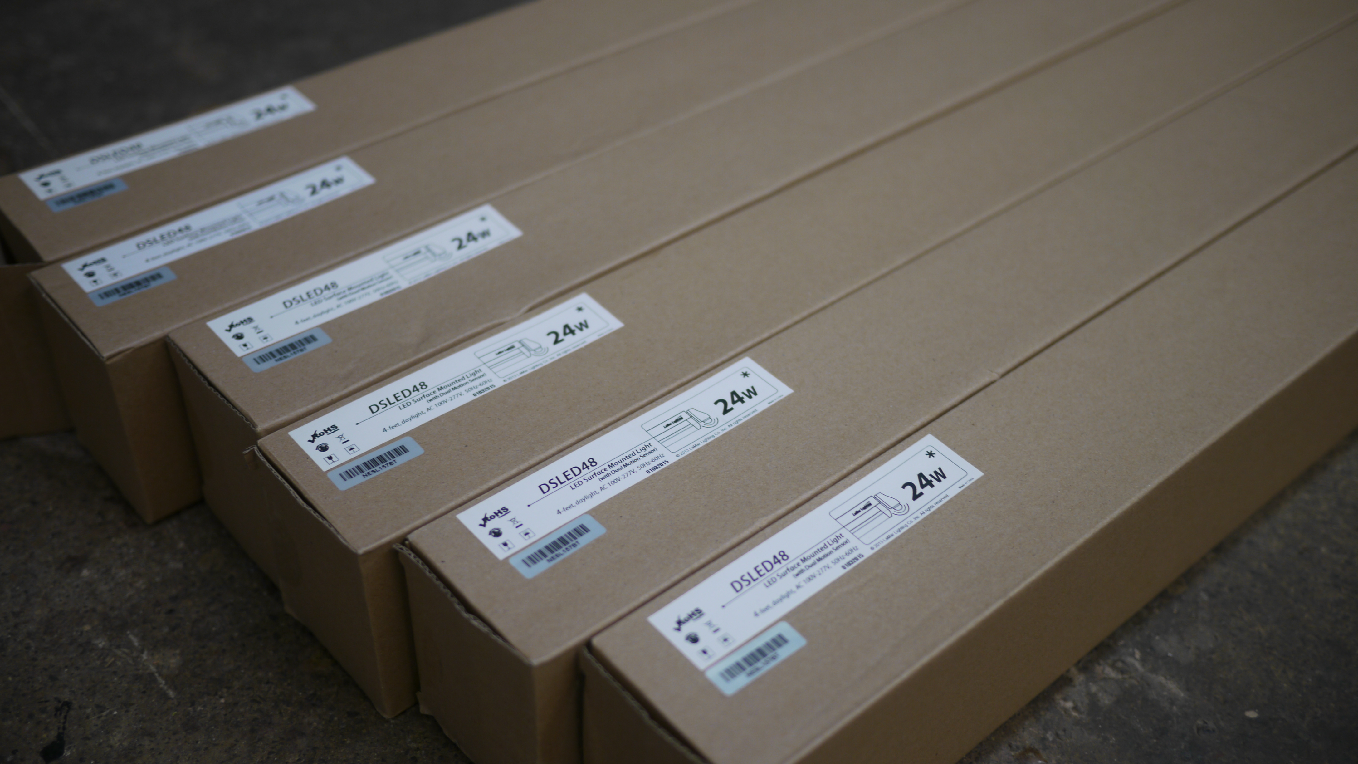 So, I lucked out quite
hard. Thanks to the ever-excellent austin, who clued
me in to a pile of led lights that were getting
scrapped. I jumped on the offer and grabbed 10 of
these 24W flourescent tube replacement lights. Nine
were slated to be used as robot lighting, as, fancy
art needs a reasonable amount of lighting. So, I lucked out quite
hard. Thanks to the ever-excellent austin, who clued
me in to a pile of led lights that were getting
scrapped. I jumped on the offer and grabbed 10 of
these 24W flourescent tube replacement lights. Nine
were slated to be used as robot lighting, as, fancy
art needs a reasonable amount of lighting. |
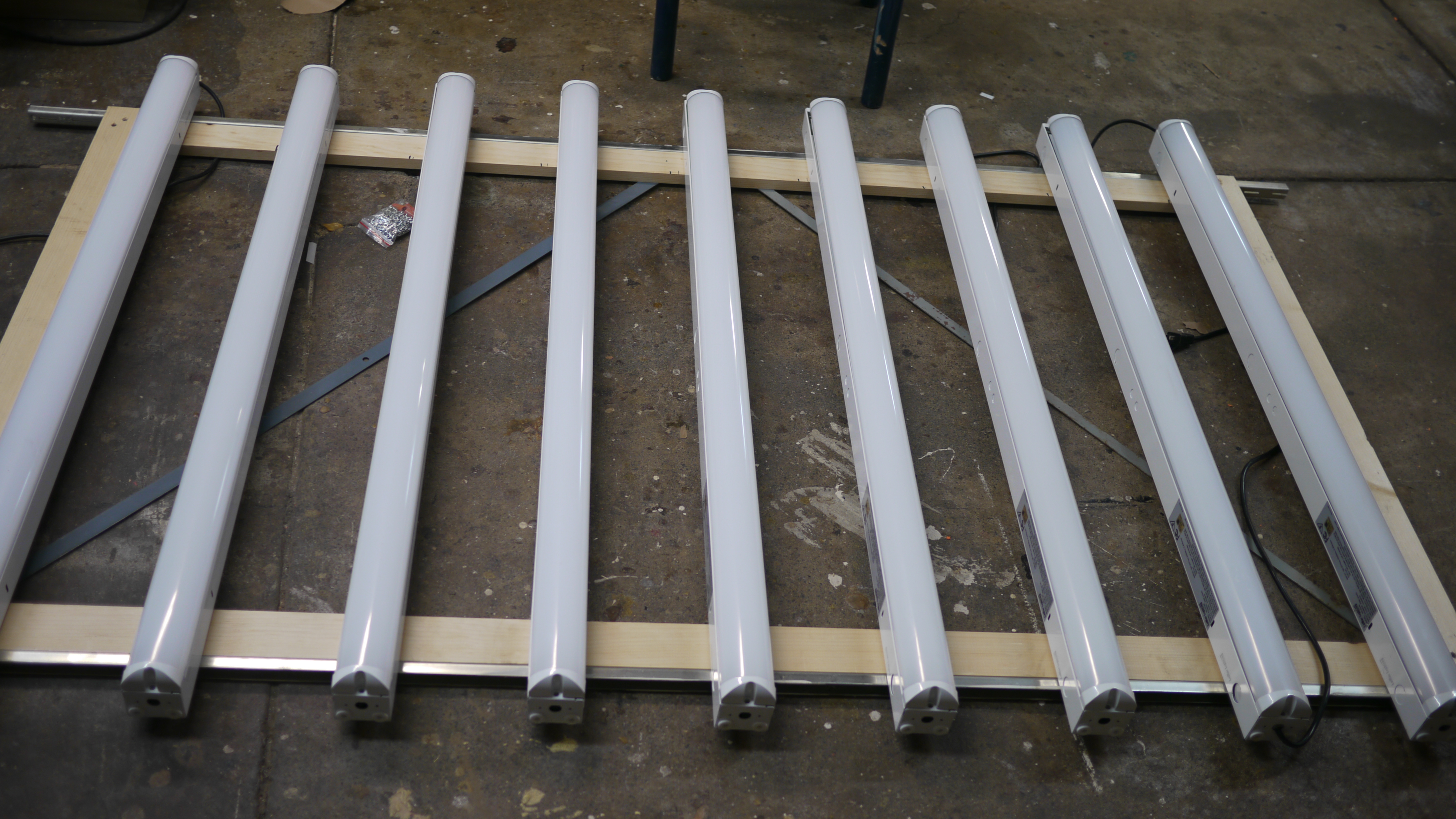  Due to the clock running
quite short, this was a bit more haistly thrown
together. Nine bulbs, spaced ~5" apart were attached
to a wood+shelving material structure and
electrically connected in parallel. A jumper was
used on each internal motion-sensor connector to
mimick 'full brightness' mode. Due to the clock running
quite short, this was a bit more haistly thrown
together. Nine bulbs, spaced ~5" apart were attached
to a wood+shelving material structure and
electrically connected in parallel. A jumper was
used on each internal motion-sensor connector to
mimick 'full brightness' mode. |
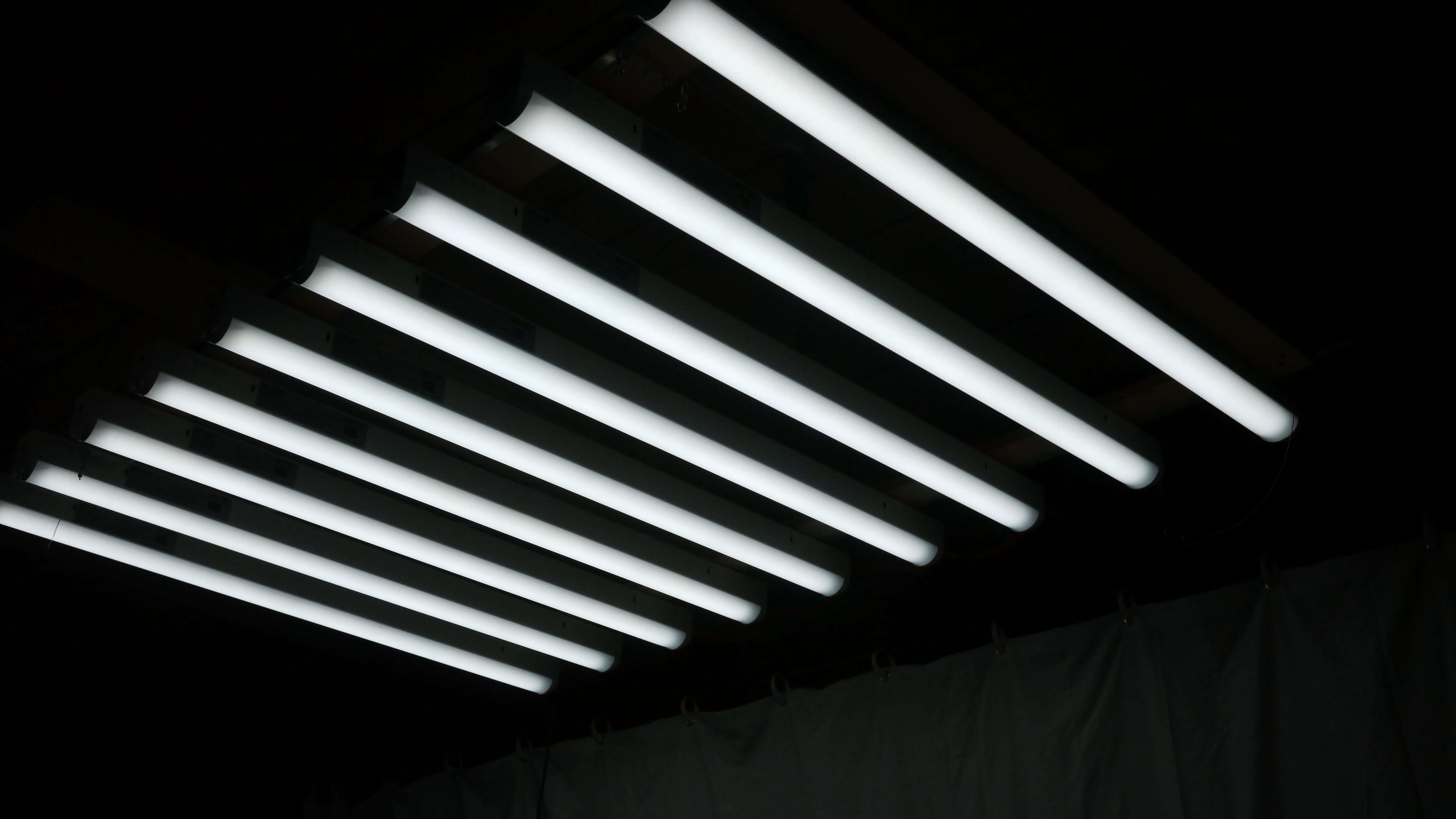  This whole setup was then
hoisted using a jume-crane onto the celing and
constrained with chains. Its quite bright at ~220w of
led. This was mostly a temporary structure, and will
possibly be replaced with something a bit more
legitimate at a later date. The light color claims to
be 5000k color temperature but appears to be on
the lower side of white (3500K?). Manual available
here [link]. Curiously they claim to
ramp from 25W at full power down to 5W at low power,
it may be useful to actually install a relay and have
the robot actuate the light intensity remotely, or
have a convenient low/high master-switch. This whole setup was then
hoisted using a jume-crane onto the celing and
constrained with chains. Its quite bright at ~220w of
led. This was mostly a temporary structure, and will
possibly be replaced with something a bit more
legitimate at a later date. The light color claims to
be 5000k color temperature but appears to be on
the lower side of white (3500K?). Manual available
here [link]. Curiously they claim to
ramp from 25W at full power down to 5W at low power,
it may be useful to actually install a relay and have
the robot actuate the light intensity remotely, or
have a convenient low/high master-switch. |
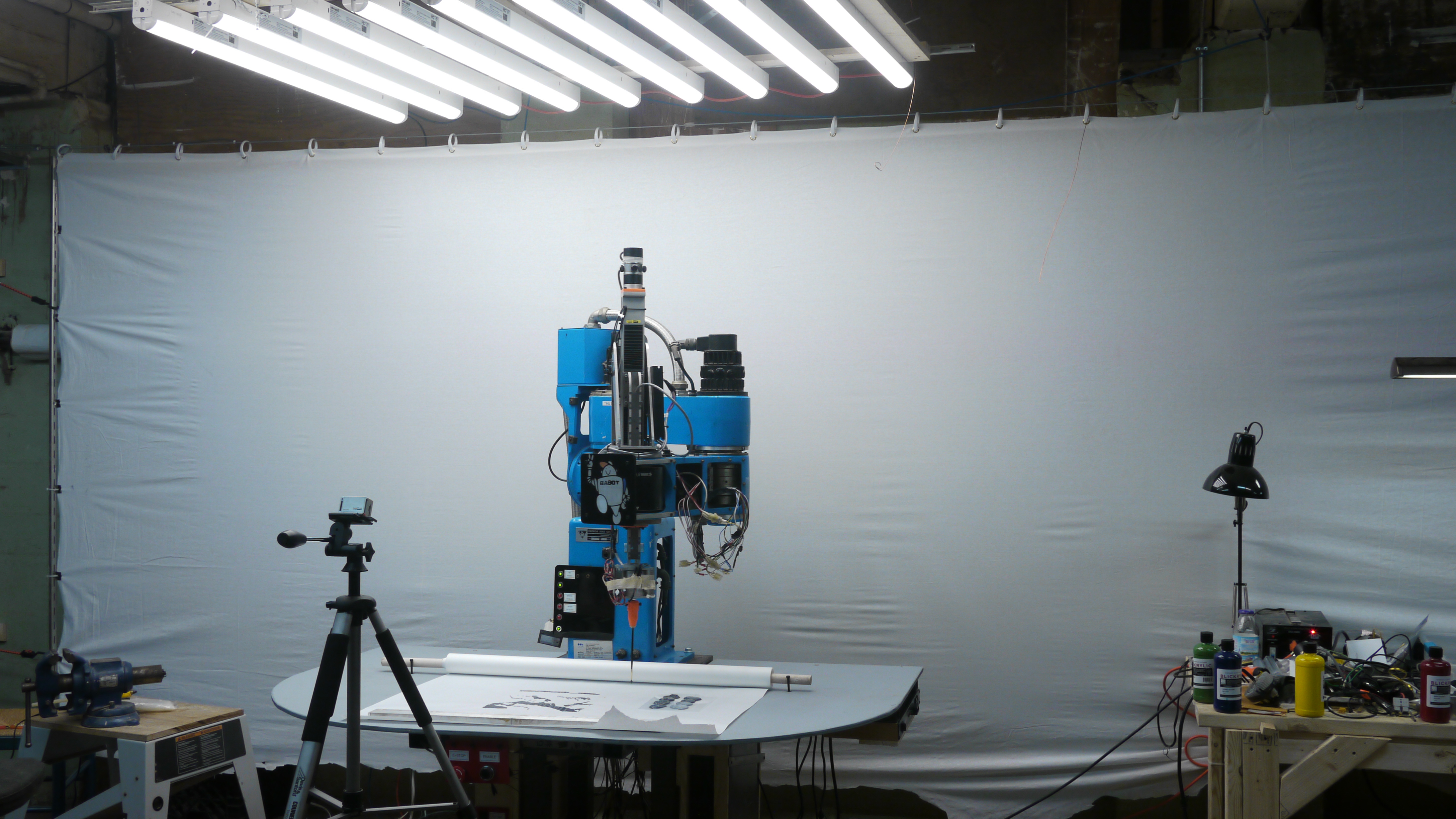
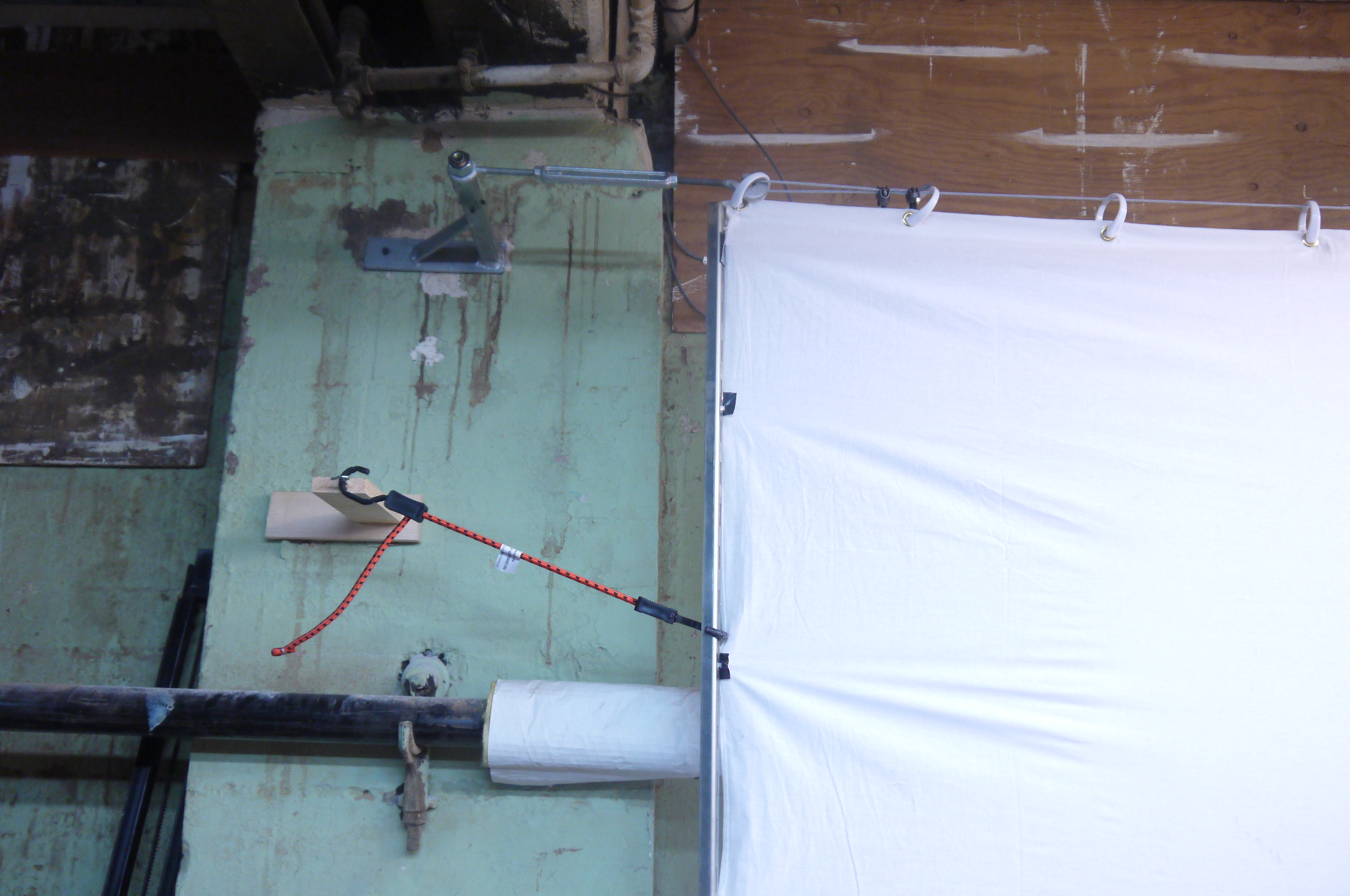
  Holdon
what is that sheet in the background? Holdon
what is that sheet in the background?To reduce the background distraction / cave like appearance of the basement, i ordered a 'frigging giant' 10' x 20' backdrop. Using it longitudinally, I ran a cable across the wall behind the robot. The curtain was held in place by two steel hangers, each mounted to the wall. A cable and a turnbuckle [link] were used to hold up the curtain under tension. |
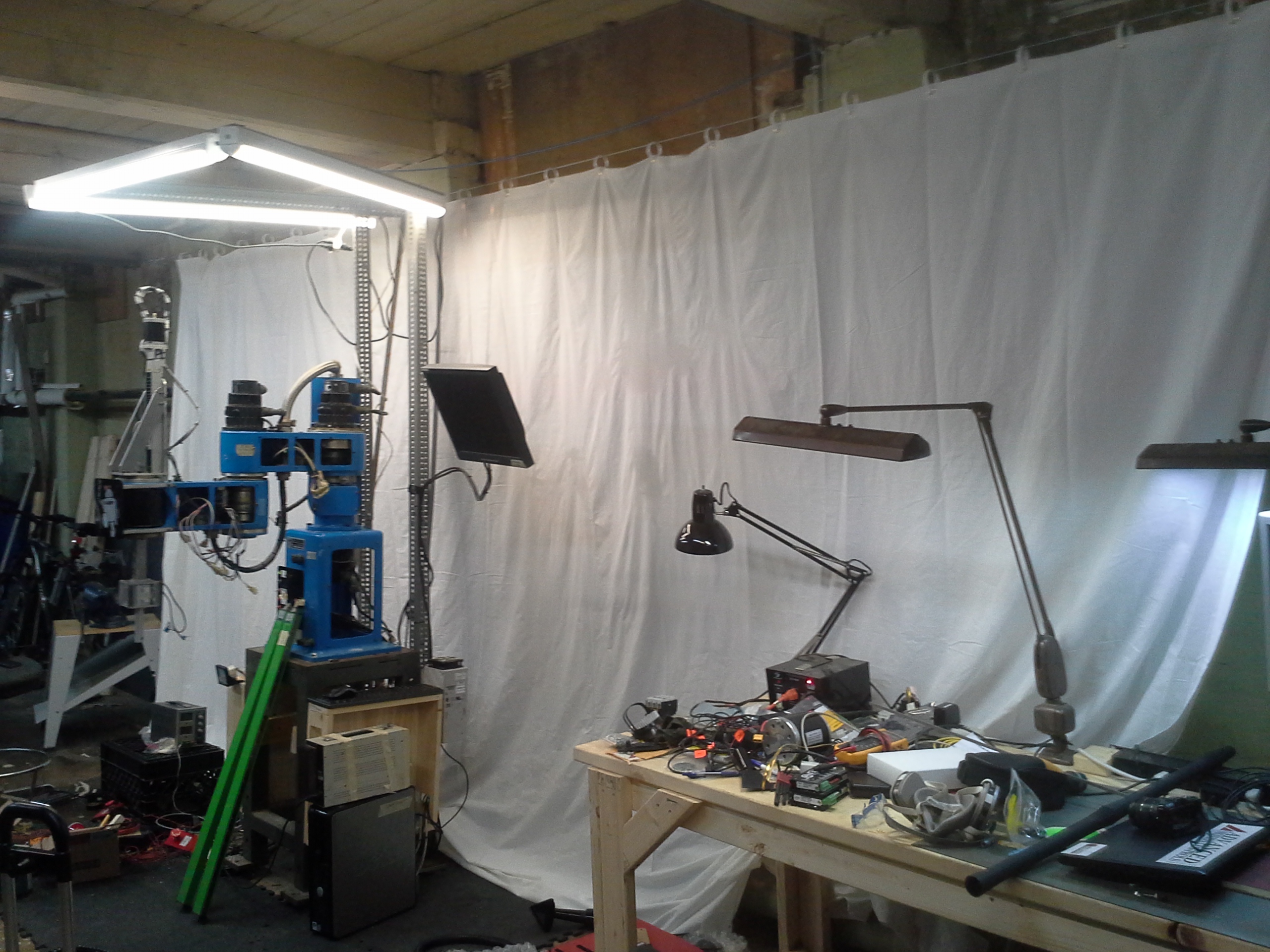
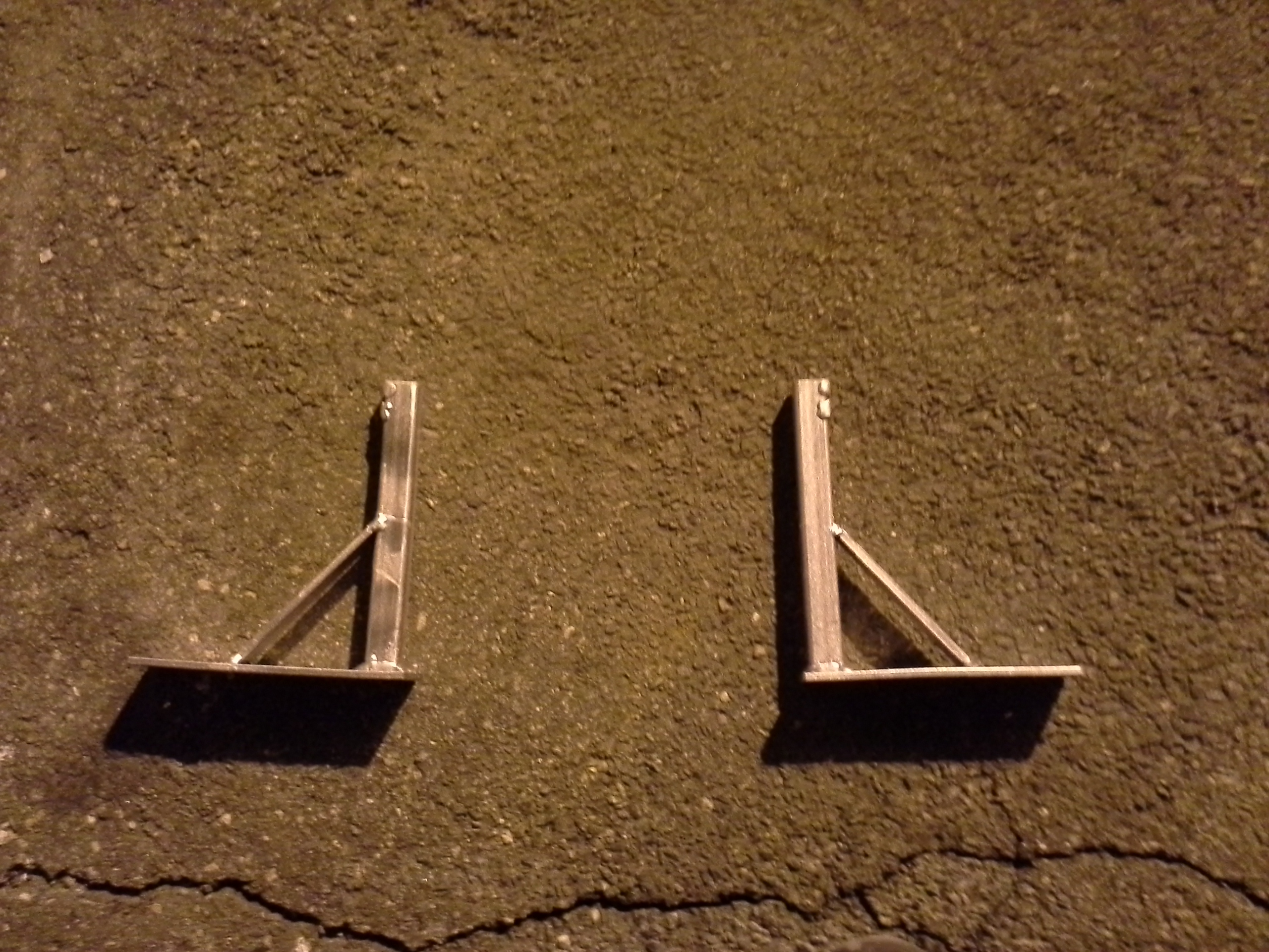
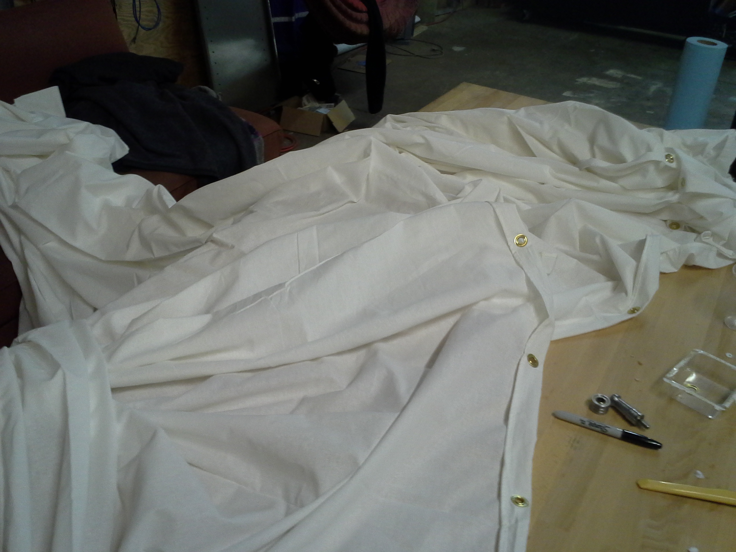 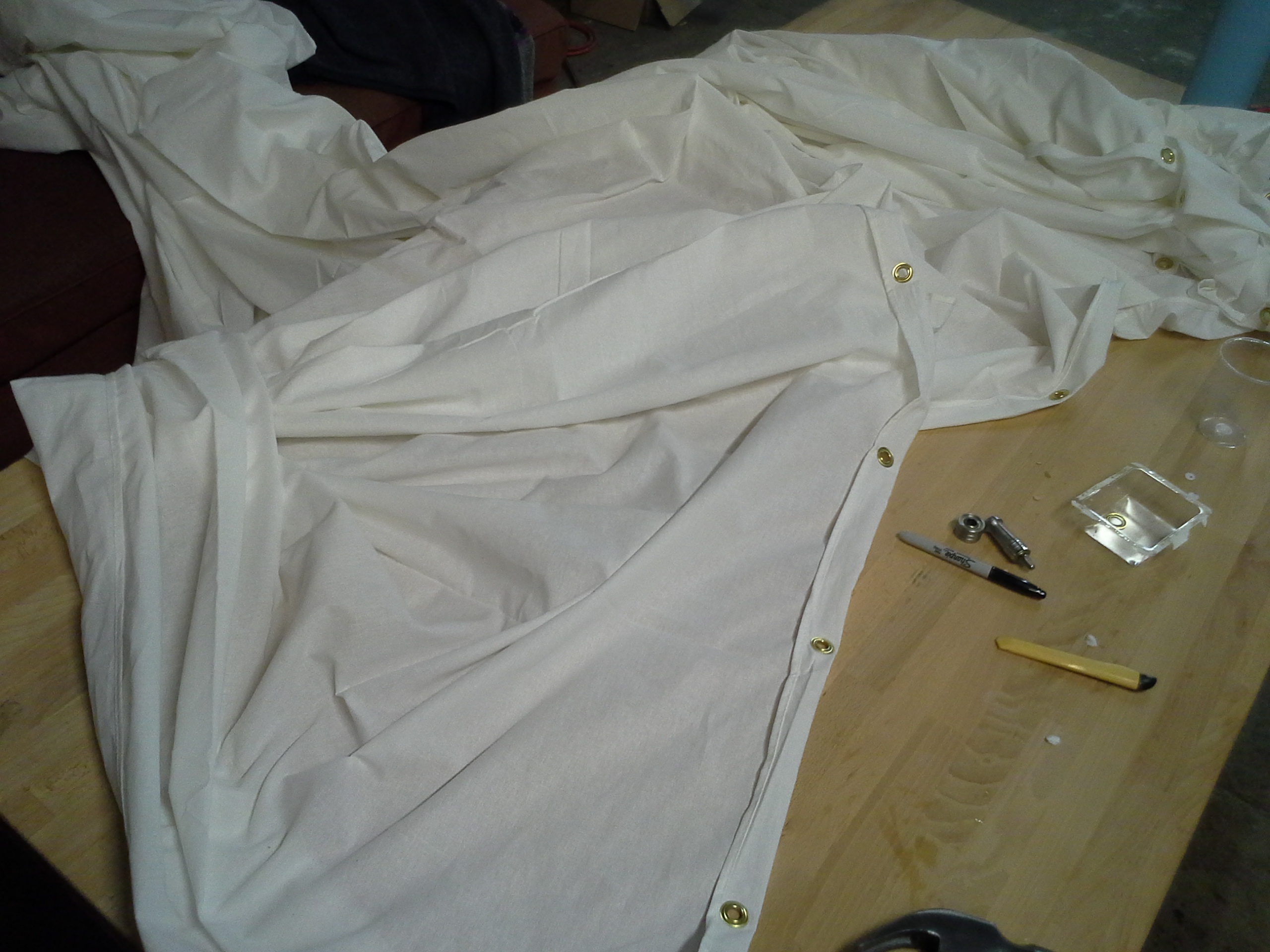 Your
photography sheet came with showercurtain hooks? Your
photography sheet came with showercurtain hooks?GROMETS! A punch & die gromet kit was used to add places to hook the backdrop onto the overhead cable. Myself and the ever excellent Sam hammered gromets in place at regular inervals and hung up 'the great backdrop' |
  Shown are the gromets and
showercurtain loops. Long bookshelf brackets were used
as a parallel surface for stretching the fabric from Shown are the gromets and
showercurtain loops. Long bookshelf brackets were used
as a parallel surface for stretching the fabric from |
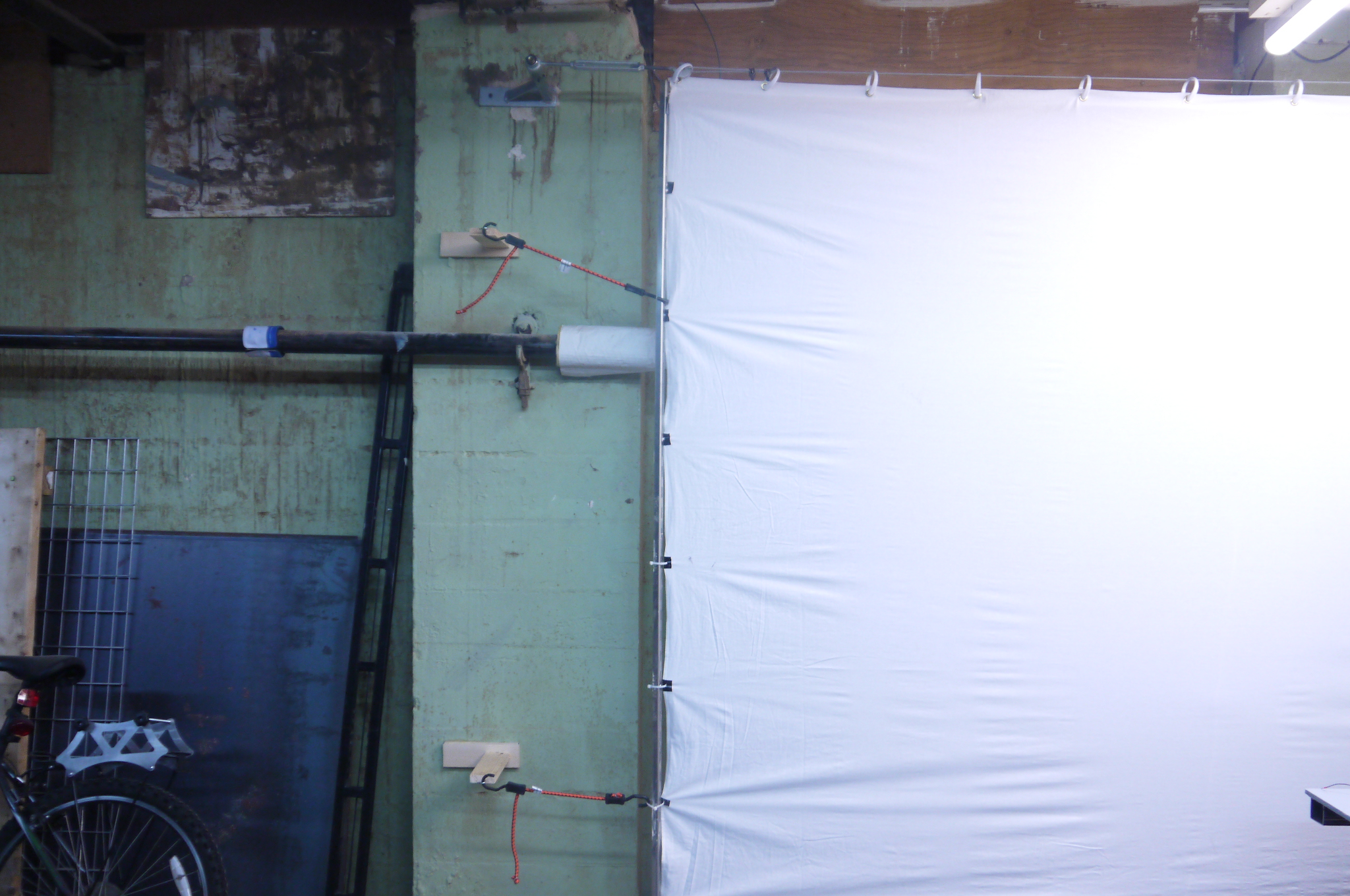
  With the backdrop pulled tight from
opposing ends there were still alot of wrinkles,
fortunatley i have a steam cleaner and after an hour
or so of blowing hot steam at a tensioned sheet, the
wrinkles faded away and the backdrop turned out
quite well! Shown right is the backdrop hanging from
the tensioned cable under the large overhead light
array. With the backdrop pulled tight from
opposing ends there were still alot of wrinkles,
fortunatley i have a steam cleaner and after an hour
or so of blowing hot steam at a tensioned sheet, the
wrinkles faded away and the backdrop turned out
quite well! Shown right is the backdrop hanging from
the tensioned cable under the large overhead light
array. |
| Remember to Wax Your Robot |
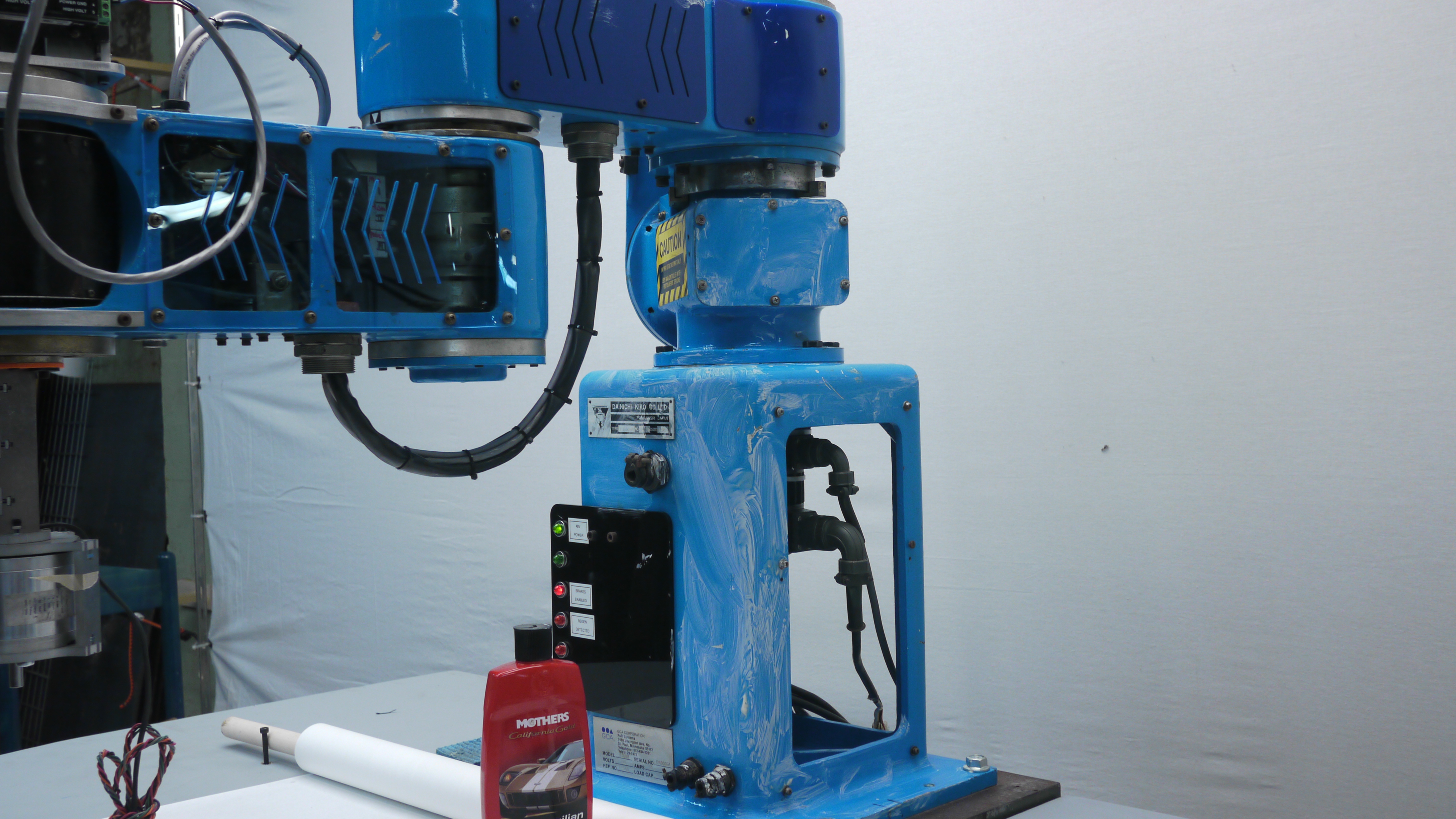 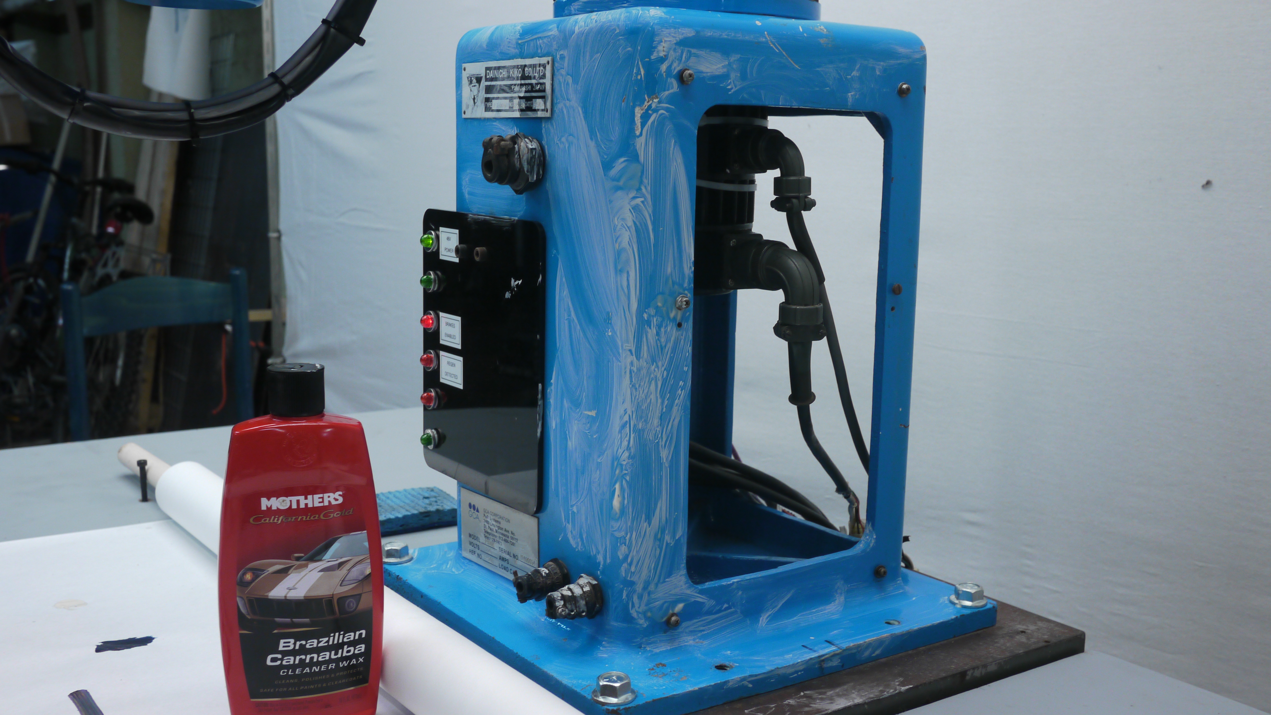 With the robot art
competition coming in near, i took my chances and
tried to pretty-up the robot. With the robot art
competition coming in near, i took my chances and
tried to pretty-up the robot. Yes, I waxed a 1980's robot arm. I cleaned down the robot with simple green, bought some 'mothers' brand car wax, used a roughing cloth to apply wax and waited for it to dry and haze up. |
  After waiting a bit, I
'put some muscle into it' and the robot shined. This
suprisingly worked fairly well. After waiting a bit, I
'put some muscle into it' and the robot shined. This
suprisingly worked fairly well. |
 Obligatory
Robot Waxing Gif Obligatory
Robot Waxing GifAdmittedly I didn't buy all that car wax just for the robot, there's plenty of other contraptions that could use some shimmer. In the process I did notice that there were a number of gouges and scratches in the paint, this bot must have had a curious life. |
| ART: Hardware and Software mixed together |
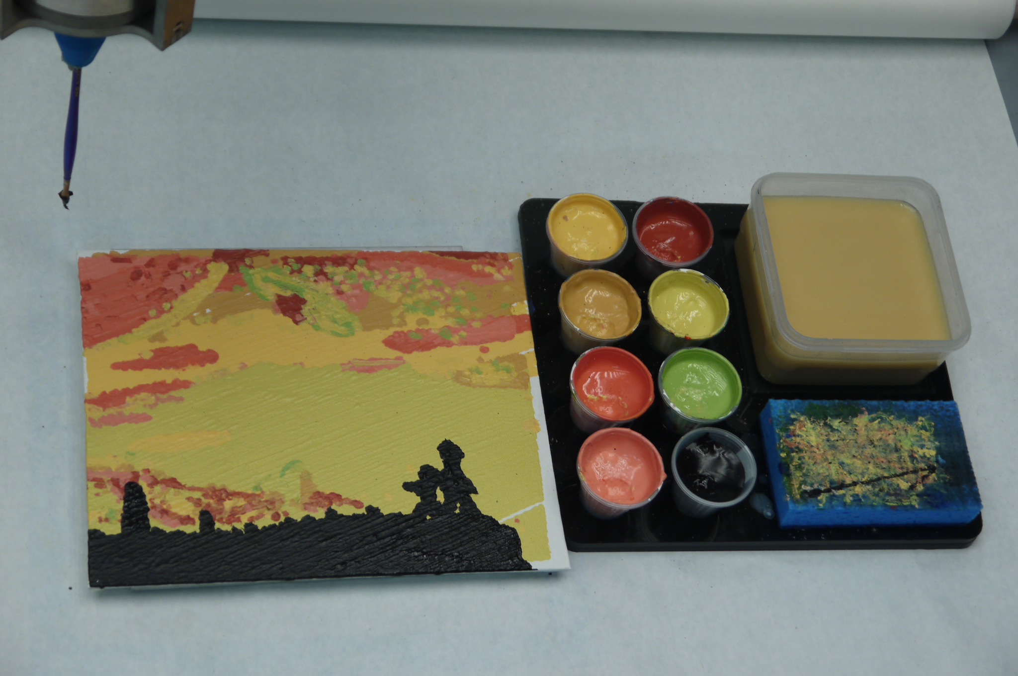
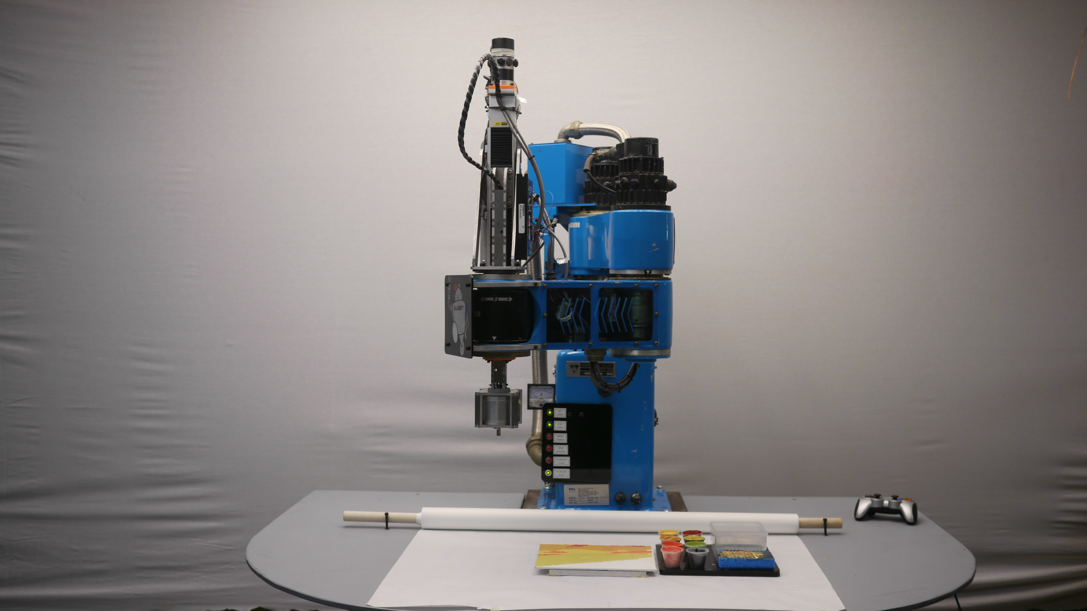
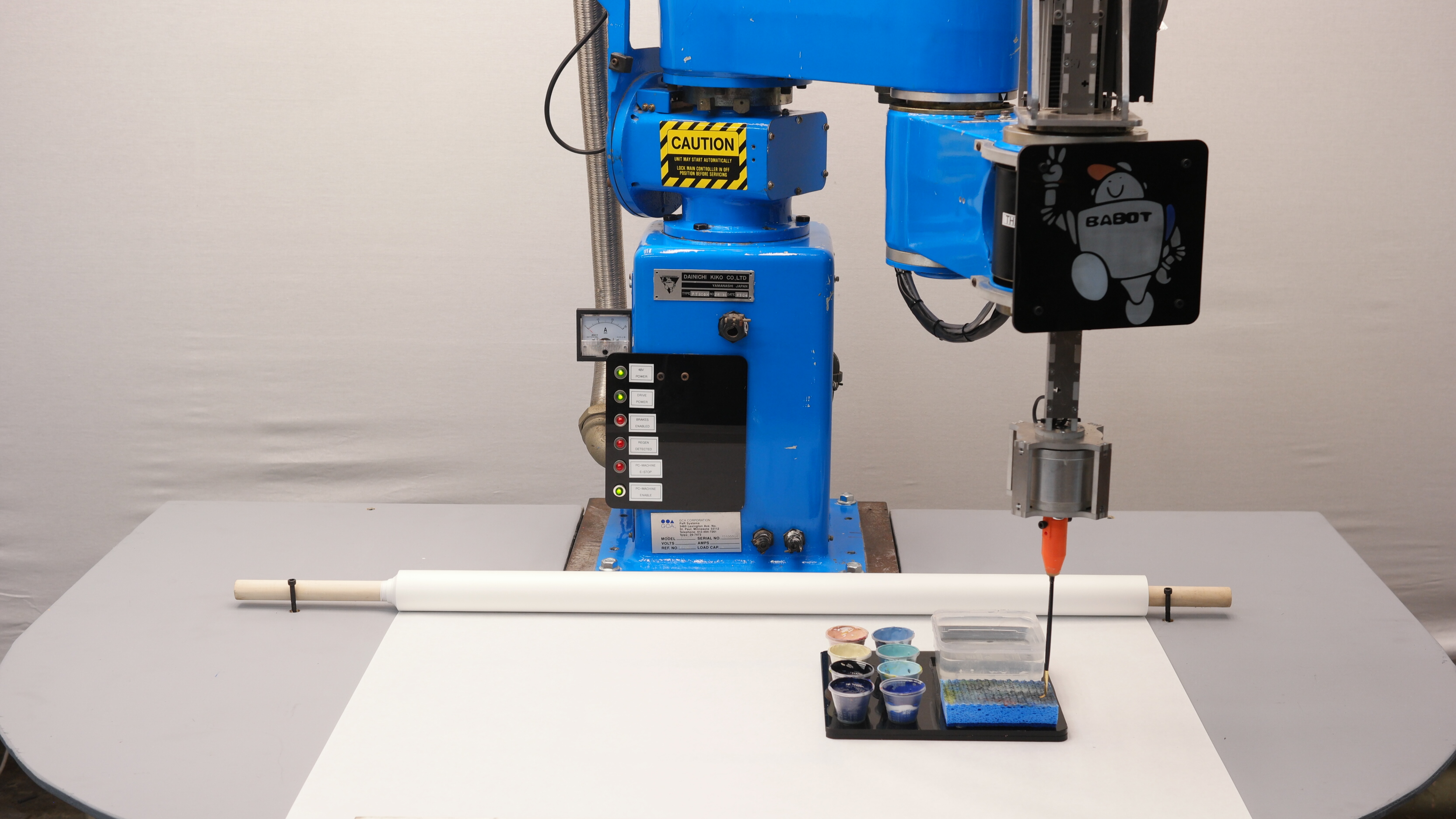
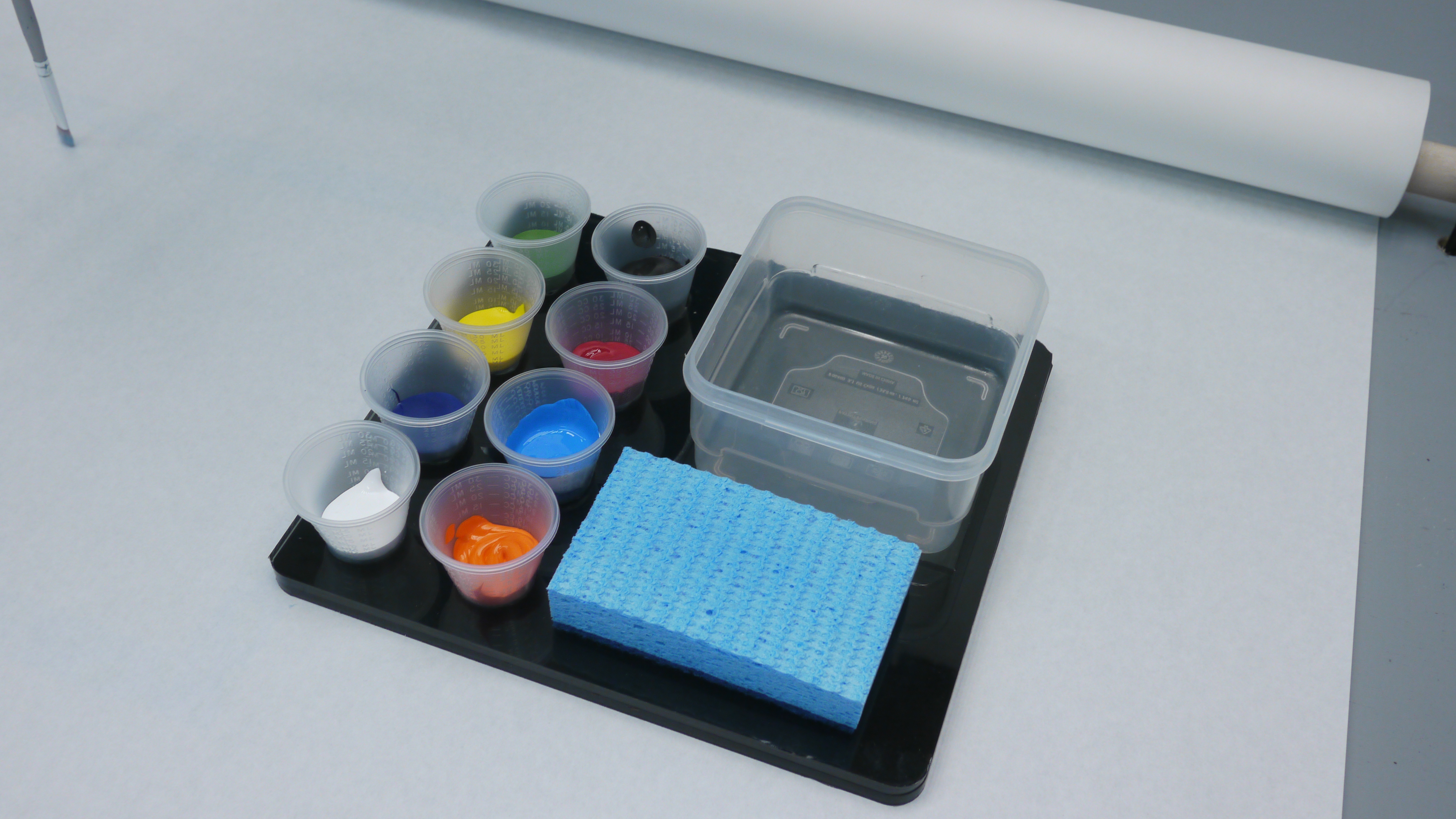
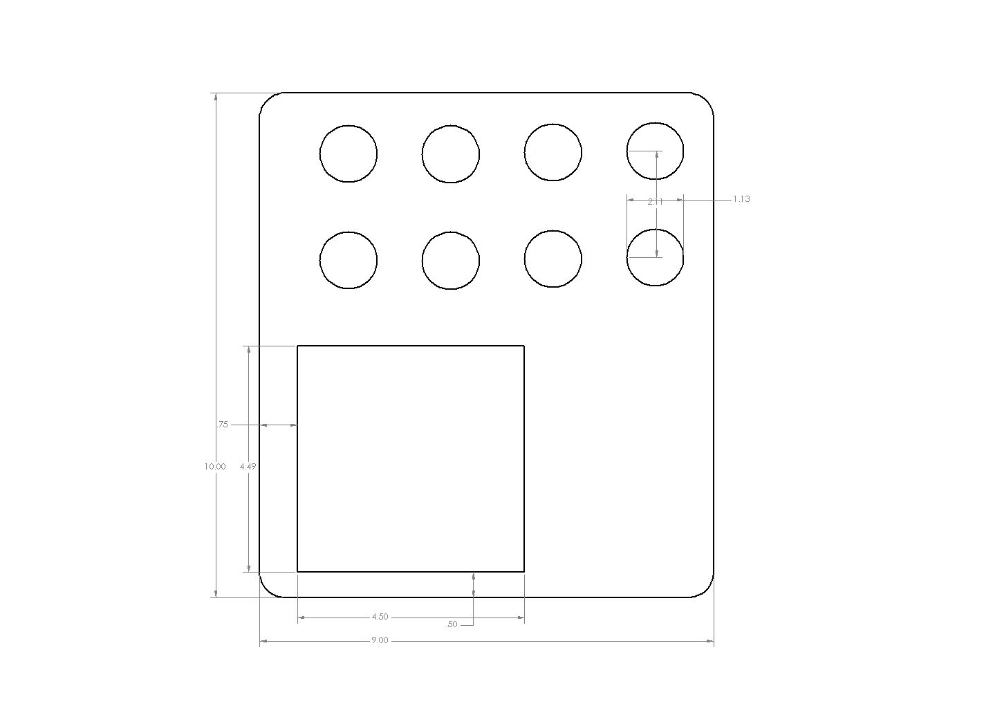 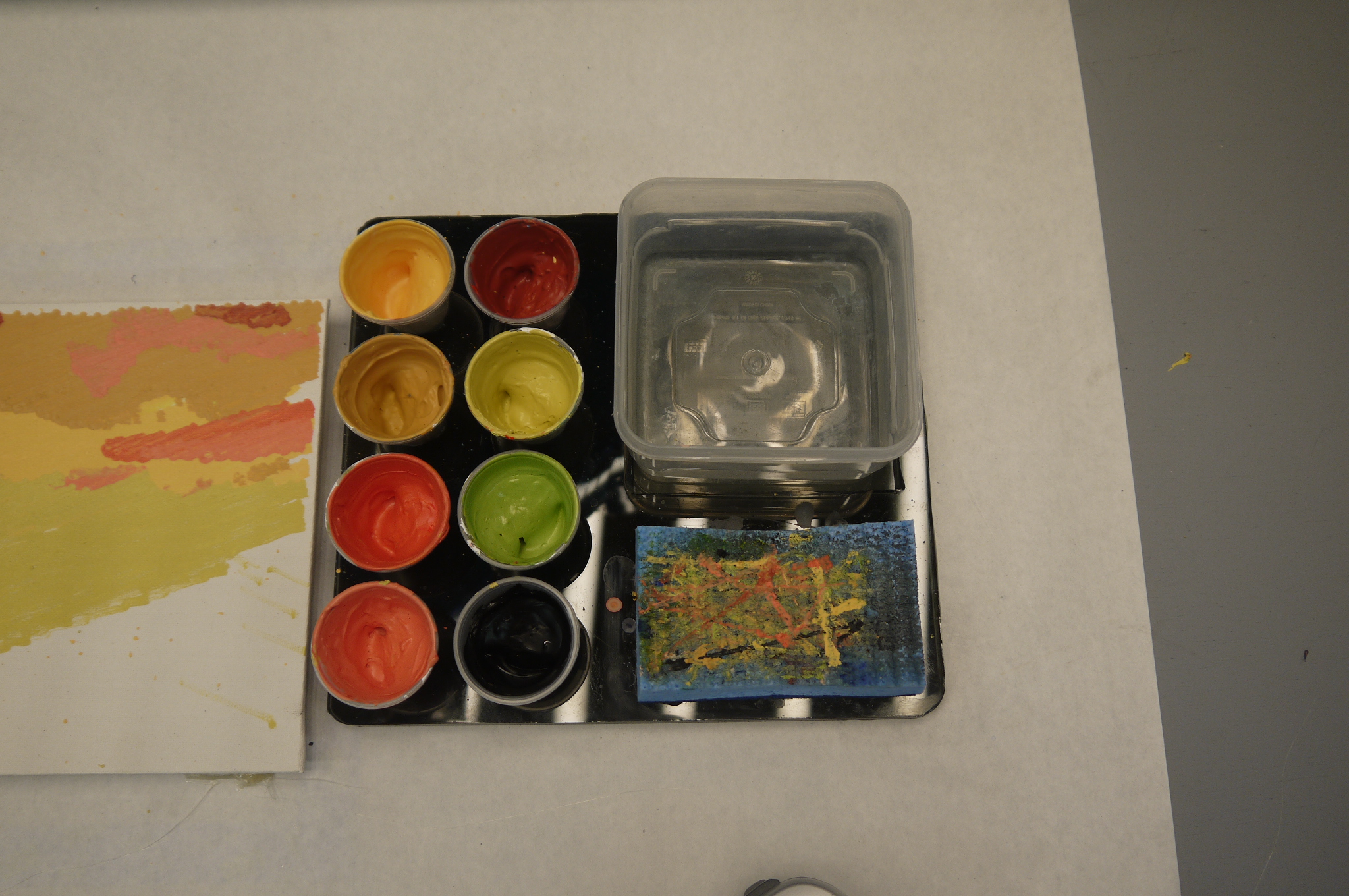 The actual 'pallet' for
generating paintings is fairly minimal, a scale
drawing from the laser-cutting is shown (right). For
the competition we're allowed 8 colors. A small
Tupperware is used as the water container and a dish
sponge is used to wipe-off the brush between color
changes. This worked surprisingly well, the addition
of a 'random walk' on the sponge was also a fantastic
idea by Sam, as its fairly clear even early on we were
fully utilizing that sponge. The actual 'pallet' for
generating paintings is fairly minimal, a scale
drawing from the laser-cutting is shown (right). For
the competition we're allowed 8 colors. A small
Tupperware is used as the water container and a dish
sponge is used to wipe-off the brush between color
changes. This worked surprisingly well, the addition
of a 'random walk' on the sponge was also a fantastic
idea by Sam, as its fairly clear even early on we were
fully utilizing that sponge. |
 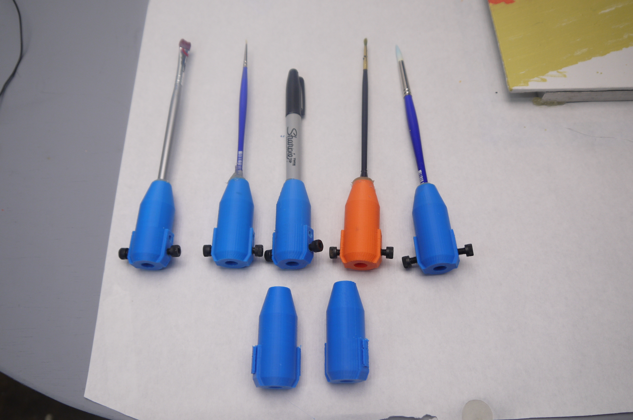 Paintbrush
holstering' Paintbrush
holstering'For the sake of adjustable and quick to reproduce, the paintbrush holsters are 3d printed. Two (or 4) M5 screws are used as finger-tightenable attachment points to the paintbrush spindle motor. The brushes themselves were set in place using hot-melt glue. Care was taken to keep them centered during the cooling / seating process. |
  The
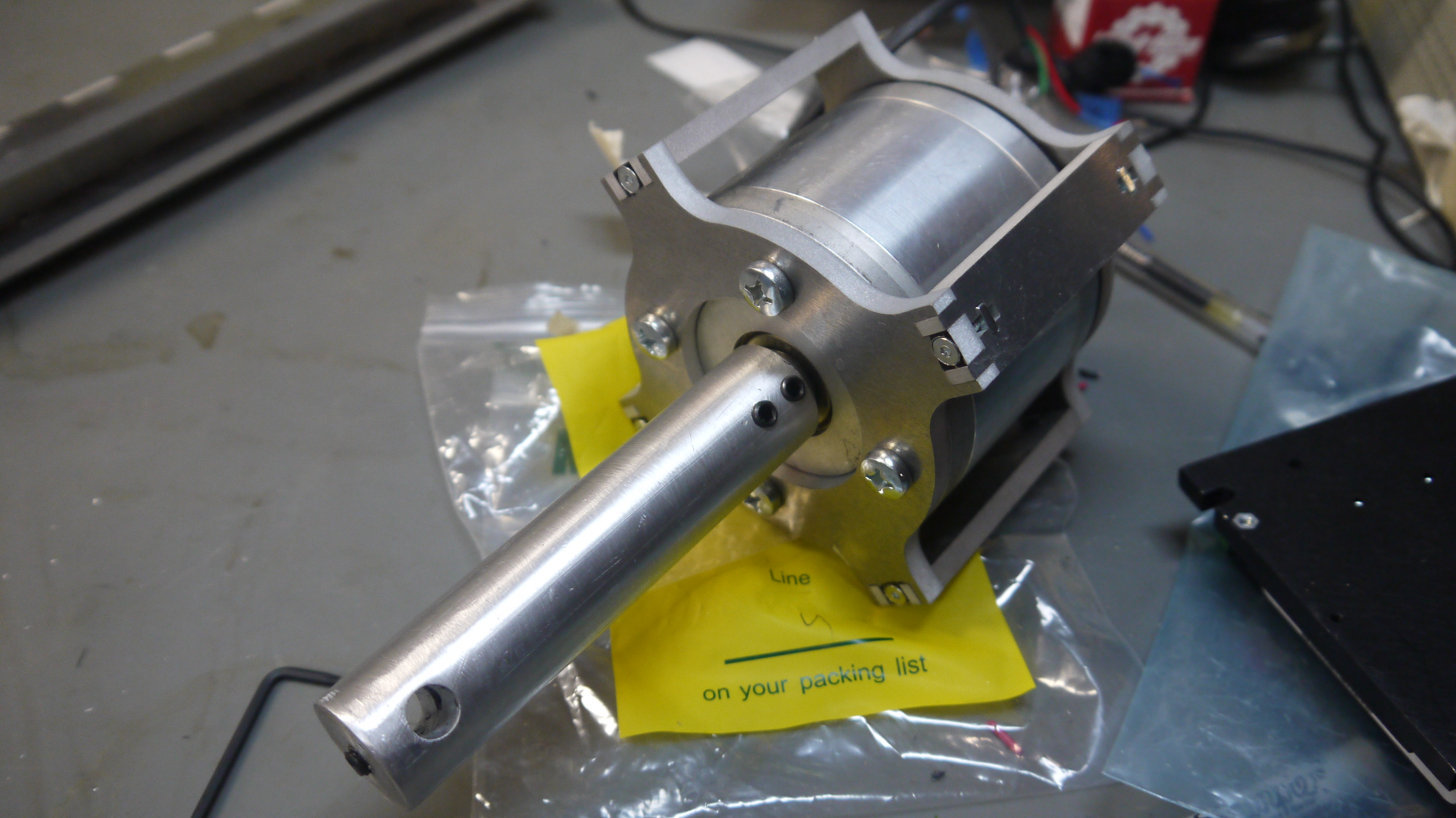
spindle motor and the auto-washing process The
spindle motor and the auto-washing processThe spindle motor itself is a brush-less dc moog motor, with 120 degree hall spacing. This is a lot of motor to spool a paintbrush, but it was what i had available on hand. It was found ages ago by the magical ben, from a lab-cleanout. |
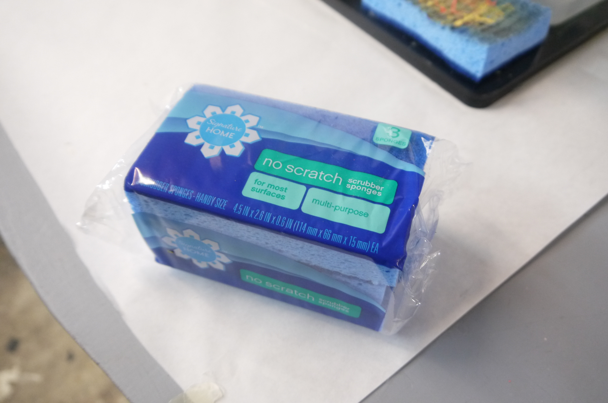 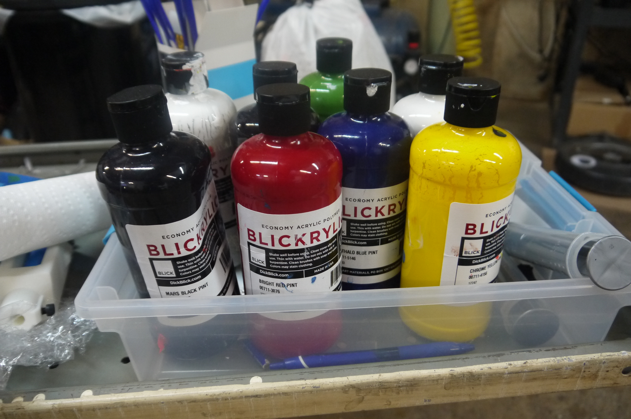 PAINT
and SPONGES PAINT
and SPONGESlike anything, painting is difficult without a useful painting medium. Oils were deemed to take way too long to dry while acrylics were way more reasonable. Curiously, there's alot of 'acrylic' out there. Loose acrylic seemed to handle better (and not dry instantly) so we opted to use well-overfilled canisters and just have the brush poke through any of the dryer film that each paint color had as it dried. Standard off the shelf scrubby sponges were used for the paint washoff process. |
 Containers
for
paint Containers
for
paintIt made sense to have a defined tray for holding the paints in fixed positions, but it was way easier to match colors outside of the paint tray, so small easy to acquire identical containers for paint holding were acquired. I opted for 'epoxy mixing cups from [link]. They are a little over 9 cents each and hold about 30mL of paint. 8 cups were glued in place as 'cup holders' and fresh paint were placed on top of the glued-in-place cups. |
| How do you coax a robot to paint? Sam's image processing and software behind the paintings. | ||
| Staring at a painting
such as Vincent van Gogh’s The Starry Night, marveling
at the complexity of brushstrokes, overlapping,
twisting, and turning, throughout the painting, we
posed the question, “How do we ask a robot to paint
something like this….?” Linux CNC provides an interpreter for G-Code, a commonly used numerical control programming language. It tells the robot where and how (e.g. speed) to move. However, how do we take an image, convert it to a set of desired paths or shapes, then translate these into a series of G-Code commands? Can we translate brushstrokes into these well defined paths? What if wanted to start from an image that didn’t have brushstrokes (a photograph), how do we define such paths? (Image Credit: moma.org) |
 |
 |
| Initially we hypothesized
that creating artwork inspired by pointilism would be
the most straightforward. This technique, developed by
Georges Seurat and Paul Signac (his work Saint-Tropez,
fontaine des Lices pictured right) in the late 1800s,
uses a brush to paint points of color which, when
viewed at a distance, create an image. The skill and
patience of an artist to master this technique is
marvelous to behold, the repeatability, the precision,
the attention to detail. Admittedly some of these
characteristics suite a robot quite well. However, we
decided we wanted to take advantage of the ability of
the robot to create lines and arcs, and to avoid what
we found to be a more inkjet printer approach. (Image Credit: christies.com) |
 |
 |
|
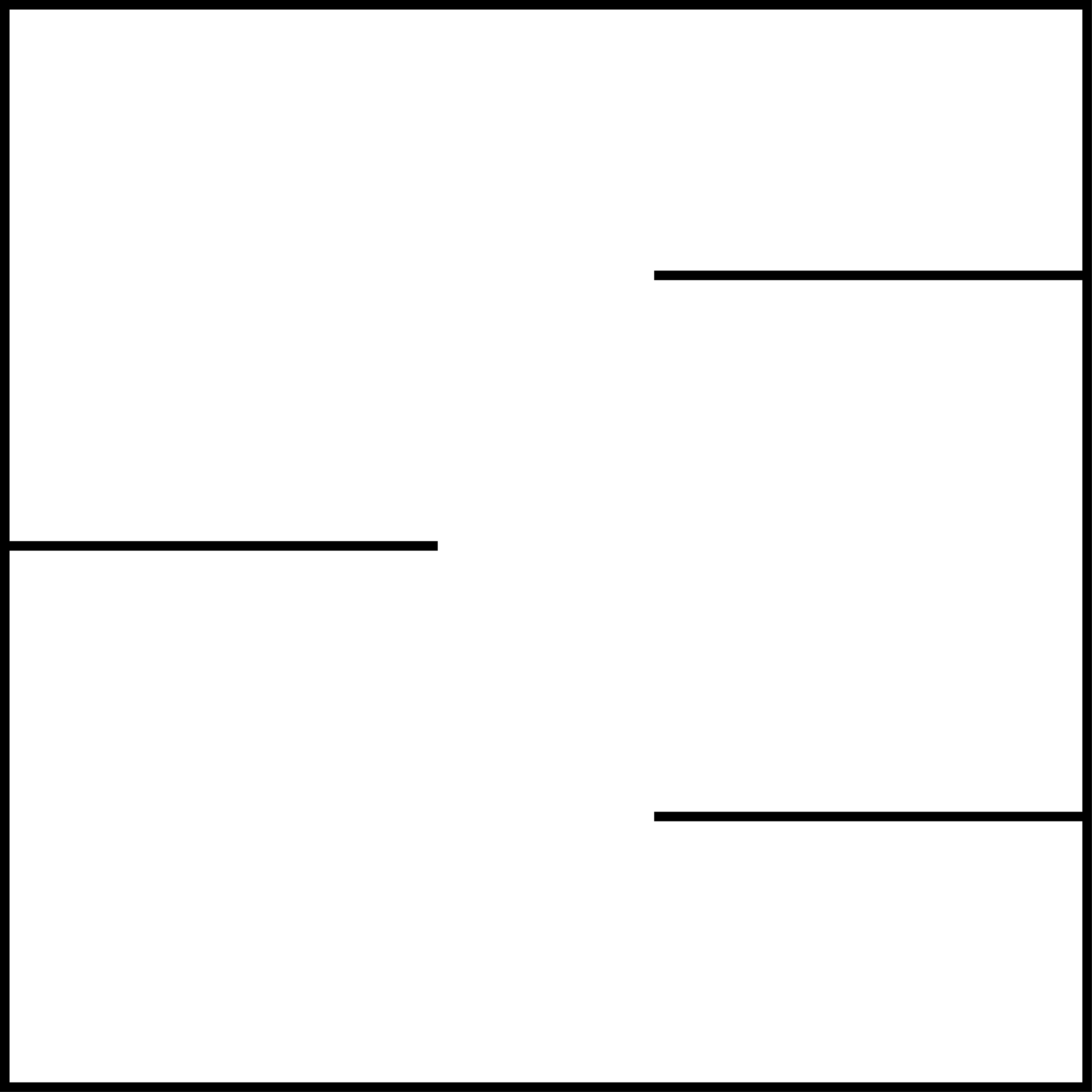
SVG files are great. Deciding to shift away from painting individual points of color as described above, I searched for a image format that was defined not by individual pixels, rather shapes and paths. Scalable vector graphics, SVG, fit the bill. They are a vector-based graphics image in XML format, a machine and human readable markup language. Let’s see what this looks like for an image composed of three lines and a square (below) |
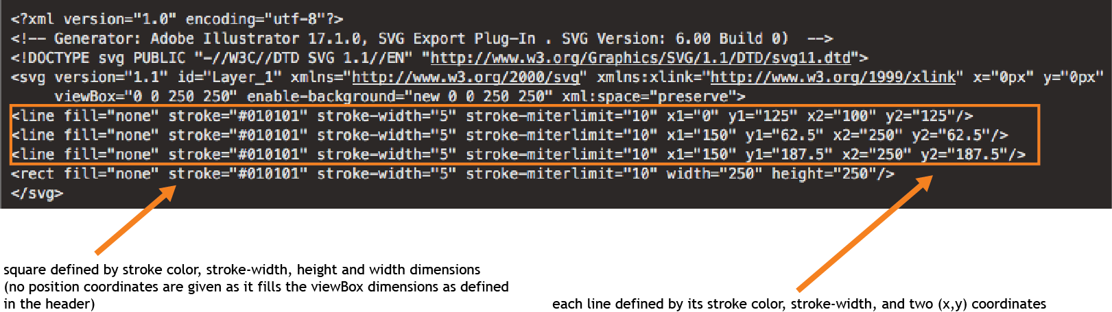 |
Code existed to convert lines
from an SVG file to G-Code. But wait! We need more
features. 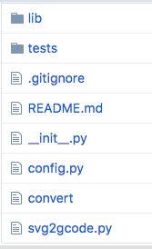 For the sample SVG image pictured above, I could manually take each of the coordinates and write the corresponding G-Code. However to generate G-Code for more complex images I went in search of existing software that would accomplish this - something that I could easily download and customize as needed. Peter Scriven’s py-svg2gcode was available on GitHub and very easy to work with. It did exactly what I needed: generated an output file of G-Code commands given an input SVG file. I downloaded the python script and began investigating to how it worked, learning python along the way (this project was a great excuse to do so in a condensed amount of time. :) ). It was clearly set-up with a main function file and a separate config.py file which contained essential system specific parameters (e.g. z-axis travel height, z-axis work height, bed size, etc…). However, there were key features I would need to add in order to generate a G-Code file that could execute tasks needed to paint a multicolored image. (-) Ensure a stroke isn’t longer than a user defined run-out length as a the brush with paint can only travel so far before the line begins to fade (-) Insert lines of G-Code to collect more paint of varying colors (-) Insert lines of G-Code to wash the brush and dry it off between paint colors |
Let’s not run out of paint,
folks! Segmenting lines longer than a user defined
‘run-out’ length.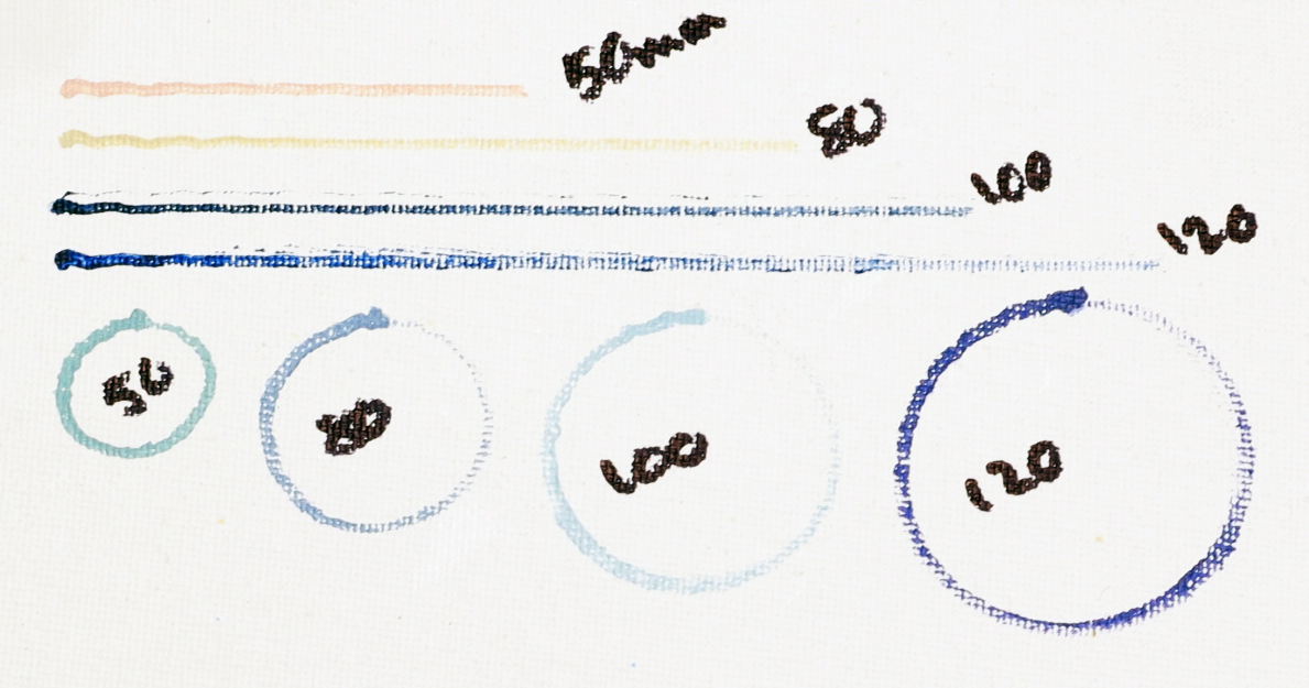 As illustrated left, a brush stroke decreases in intensity as it runs out of paint. To avoid this, we will need to collect more paint after a user defined run-out length, a parameter added to the config file. To accomplish this additional paint collection, the algorithm first approximates the X and Y coordinates utilizing recursively divided Bézier curves as in the original py-svg2gcode. I added an extra subdivision step following this procedure which segments paths longer than the user defined run-out length. Next I modified the G-Code generation loop. It now keeps a running sum of the distance traveled with each new collection of paint, looking ahead to see if the next stroke will exceed the run-out length. If so, a command calling the collect paint subroutine (described below) is generated and the running sum is reset to zero. |
Replenishing the brush with
paint: G-Code subroutines, O-code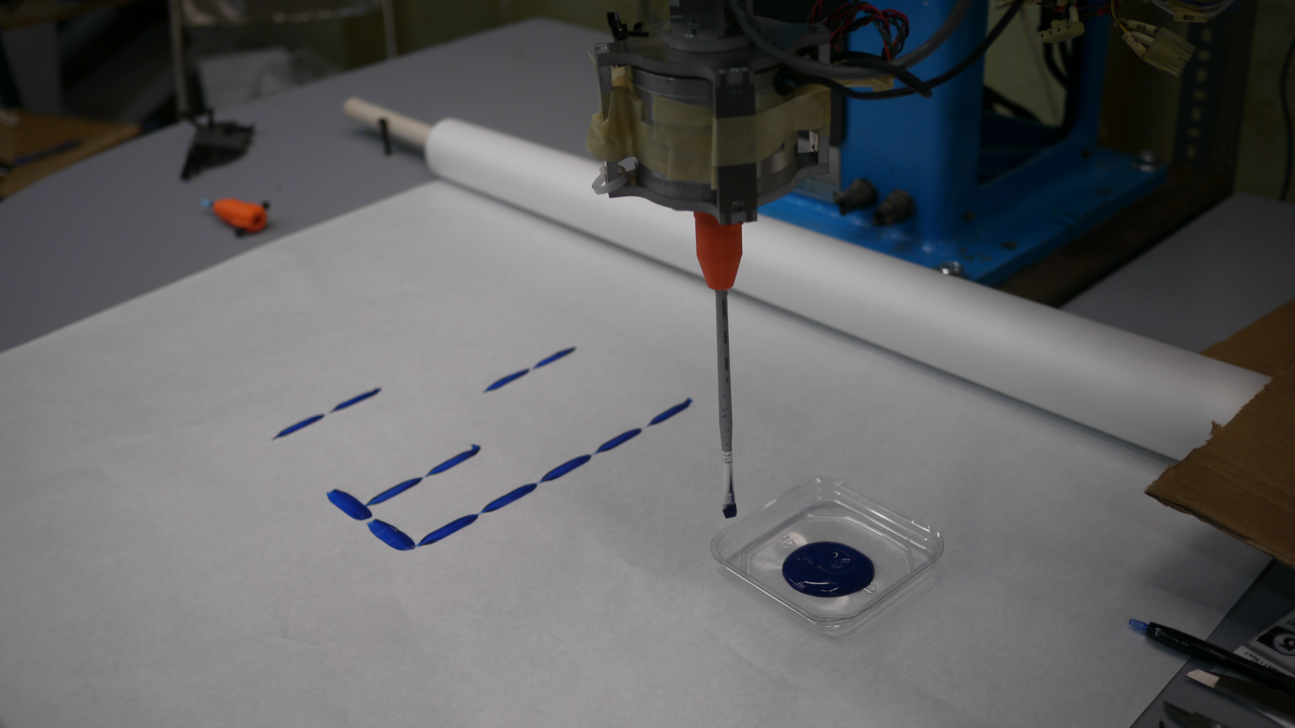 G-Code can contain subroutines, O-Code, for repeated tasks. I utilized this for collecting paint as it would allow for more easily human readable G-Code output. This subroutine was called when the running sum exceeded the runout length. For ease of readability, I used a named file. Positions were defined based on the sketch to the right. Be sure to set the travel z-height (in config file) high enough so it travels above the tray! Troubleshooting: We noted that when returning to the same position in the paint well, the brush formed a dimple in the paint. To avoid this I added two inputs into the subroutine which were randomized each time it was called, adding a bit of randomness to the how to we avoid a dimple in the paint well? Add randomness to where the brush dips using input parameters into subroutines. |
| Final subroutine: o<updatepaint> sub
Syntax to call the subroutine: G0 Z60 (z-axis travel height) G0 X[30.116+#1] Y[287.10475+#2] (position above paint well) G0 Z-22 (z-axis height in paint well; #1 and #2 are inputs) G0 Z60 o<updatepaint> endsub o<updatepaint> call [-2.52] [2.17]
(values are randomly generated to vary where brush
dips)
WE NOW HAVE THE ABILITY TO PAINT! |
Colors! Extracting them from
an SVG file and generating custom subroutines Remember how I said SVG files are great? Their ordered XML tree structure allowed for me to easily add a few lines to the python code which extracted the color of each shape. This allowed creation of 8 custom subroutines that went to each color’s respective paint tray location. The color order was also recorded recorded in the log file - this is essential when placing the colors in the paint cup tray to ensure they are in the proper location 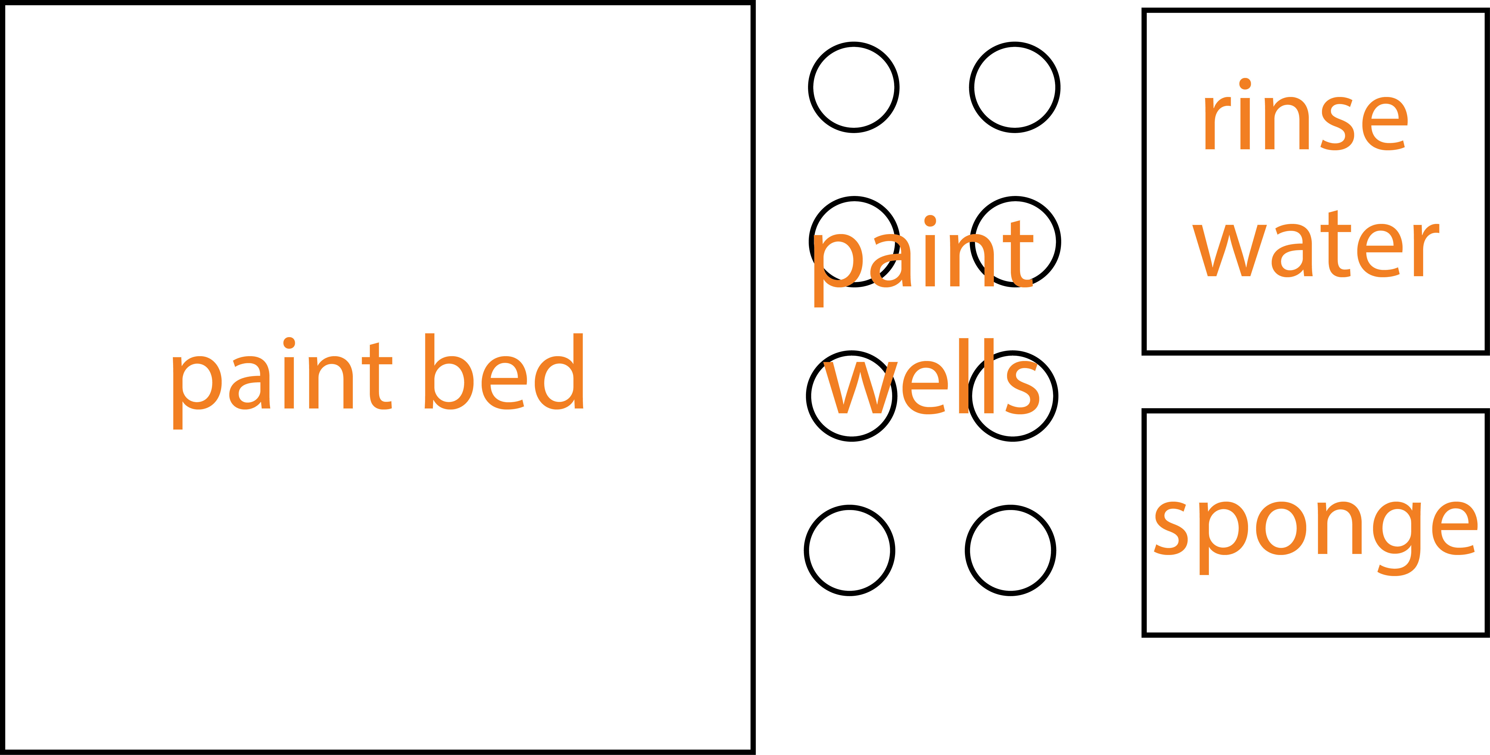 |
| Washing
the brush: turning on the spindle using M-Code http://linuxcnc.org/docs/html/gcode/m-code.html M101 File -turn the spindle
on
#!/bin/bash
halcmd setp parport.0.pin-03-out True exit 0 M102 File - turn the spindle off #!/bin/bash halcmd setp parport.0.pin-03-out False exit 0 |
Back to SVG file processing:
turning filled regions into lines for conversion to
G-Code.  Adobe Illustrator has a ‘scribble’ effect which worked quite nicely to convert a filled SVG shape into a series of parallel lines. This is one of many ways this can be implemented. The Evil Mad Scientist Wiki has a nice description of how this can be accomplished in InkScape as well. To start, I chose Illustrator simply as it was a program I was more familiar with. Future plans include exploration of effects that will vary line direction. A disadvantage to the current approach is the lines are all parallel and not dependent on general shape direction, which may not always be desired. |
| And finally some image
processing: turning a photo into an SVG file Now that we’ve developed a workflow to convert basic SVG shapes into G-Code for BlueBot to paint - what about a photograph? We need to convert the photograph into an SVG file. There exist several online tools to do so - I found inkXE’s Online PNG to SVG converter suite  d
fo d
fo r
our purposes as it retained color and allowed for
definition of how many colors were desired in the output
SVG. r
our purposes as it retained color and allowed for
definition of how many colors were desired in the output
SVG.(Image Credit: Reddit User permacultureexplorer) |
Overview of software process.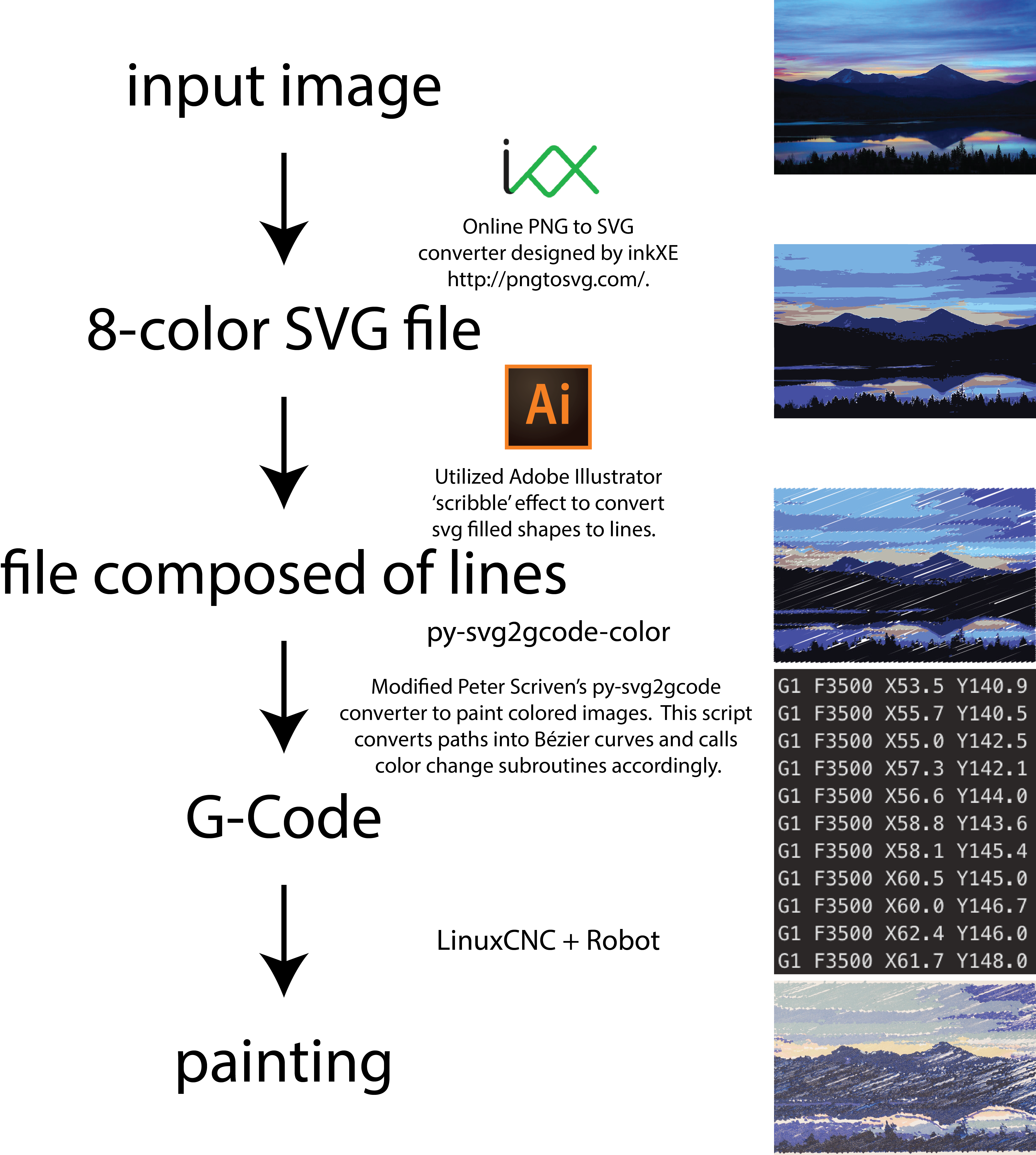 Py-svg2gcode-color code can be found from sdstrasser on GitHub Addjust all z-offsets in config file, Don’t break a brush! |
|
Painter’s Algorithm: Manually turning SVG colorized image into layers background, midground, and foreground As illustrated by the videos below, the painting process itself is entertaining. To facilitate this, reference images were manually assembled to follow the ‘painter’s algorithm’, layering background, midground, and foreground. This also clues-in the viewer to the image content earlier than painting in color order only.     |
|
A QUICK NOTE ABOUT
ROBOT ART robotart.org is having a competition click here, check out robotart & vote! <requires facebook login, I know I know> |
|
| VIDEO | |
| MEGAMAN Megaman was a fun painting, it is based off of a rather awesome 8 bit art and painted with a large format brush  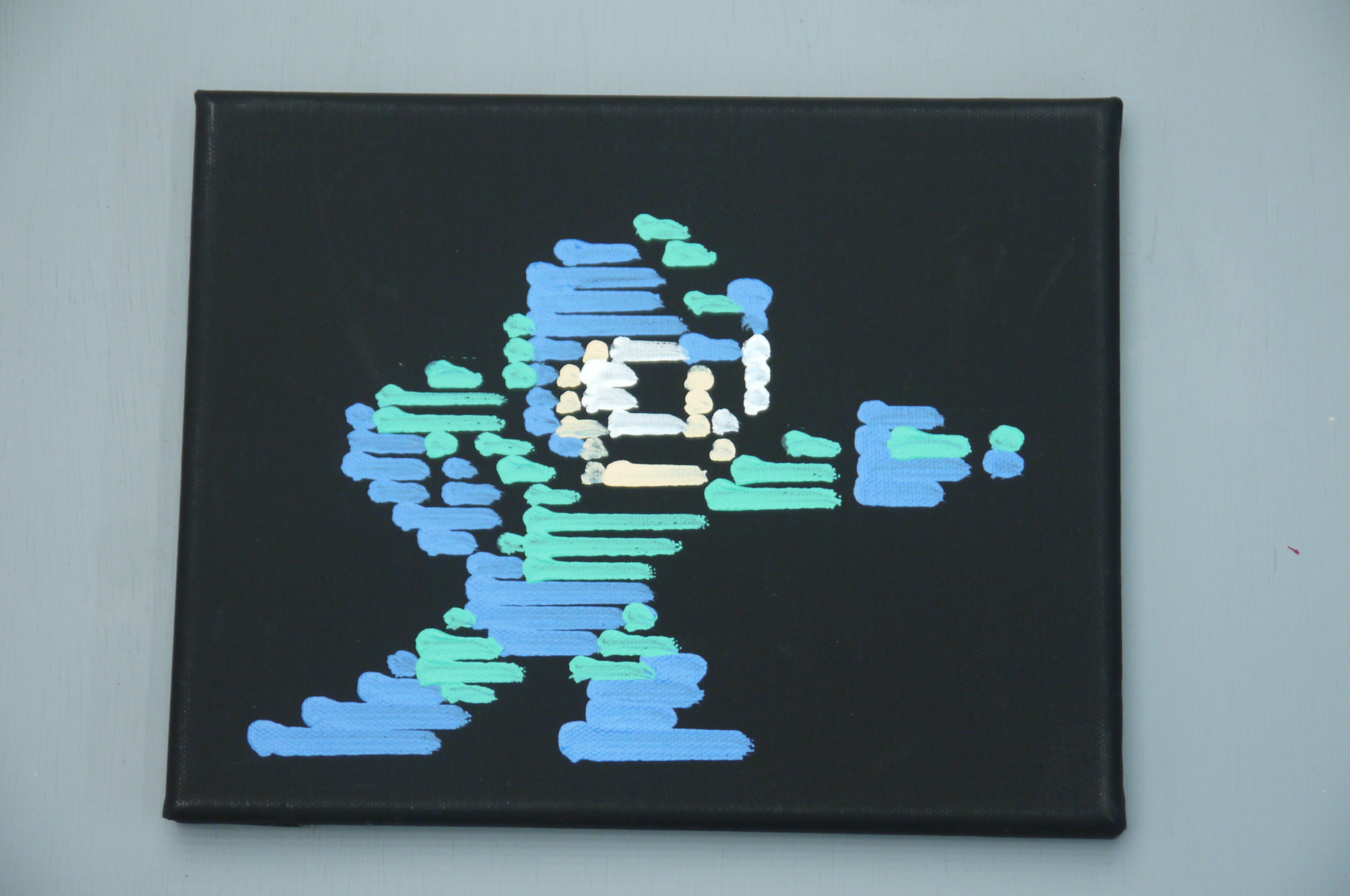 Vote for MEGAMAN Here |
|
| Sunset
Mountainscape This was an experiment in overlap variables to determine how well fill ratios vs painting time worked out, i like how the reflection is still visible in the painting. 
 Vote for Sunset Mountainscape Here |
|
| People in Space For this painting, we took a layer approach to get the painting to grow over time, this resulted in the painting 'coming together' as it was being made instead of it being abstract until the end. A full fill was opted for and it may have resulted in oversaturating the characters, but overall i found it entertaining to watch. 
 Vote for People In Space HERE |
|
| Circles and
Lines A good introduction to the paint-changing and color swapping for an abstract piece on lines and splines  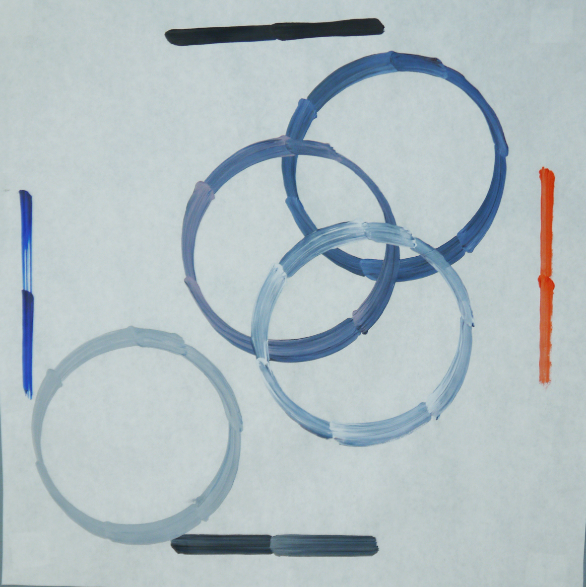 Vote for circles and lines HERE |
|
| Babot First attempt at a painting, the robot paints its own logo. This is pre-color-mixing 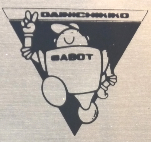
 Vote for BABOT HERE |
| Bill Of
Materials [Including fabrication hardware / consumables]
|
# Required | Cost Used no shipping
[EBAY] |
Cost New [Actual] |
Manual | Media |
| Shunt Regulator: SRST50G [Advanced
Motion Controls] The shunt regulator is a rather simple 'If voltage is above X, turn on a clamping resistor, rather quickly' device. I started lt-spicing up a quick comparator model and before i got the chance to finish, i found a |
1 | 45 [link] |
100 [link] |
[Link] | 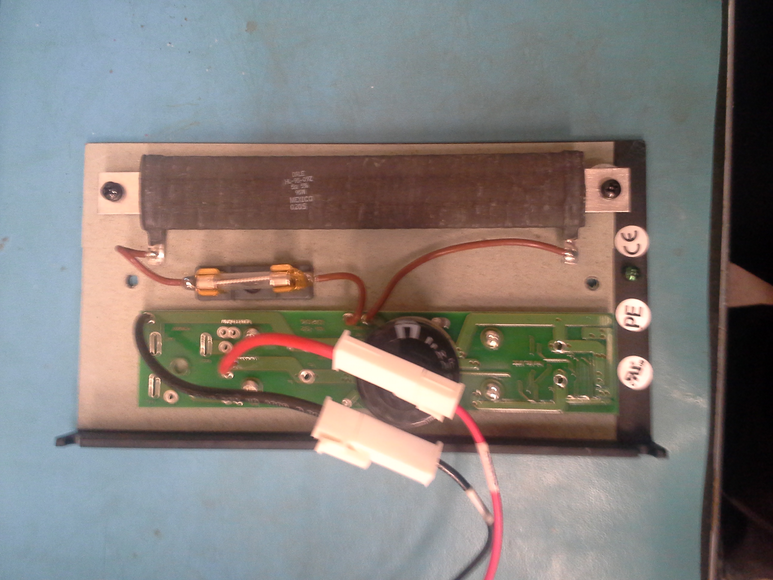 |
| Servo Drive [Theta 0,1]:
25A8 [Advanced
Motion
Controls]
I was fortunate to have one of these drives on hand from a lab cleanout, but purchased the second for the second theta. I debated using an existing extra 12A8 Brushed servo drive for the second theta, but determined that 'tuning the servo drives in software is a pain' and decided to only do it once. |
2 | 35.00 [link] |
375.00 [link] |
[Link] | 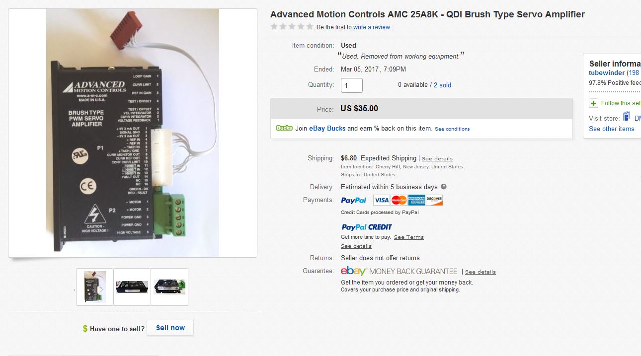 |
| Servo Drive [Theta 2]: 12A8 [Advanced Motion
Controls] I had an extra drive on hand, theta 2 is fairly low load so the lower current drive seemed a reasonable choice |
1 | 75.00 [link] |
------ | [Link] | 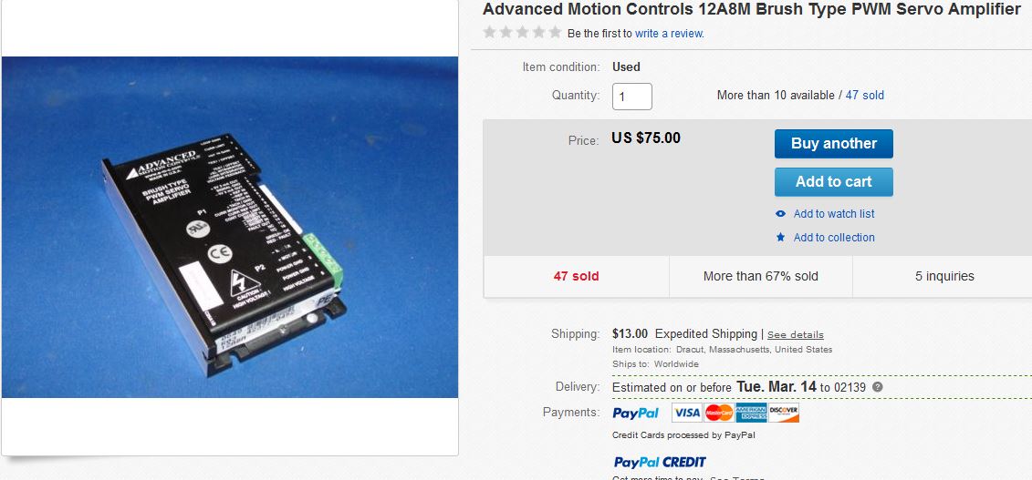 |
| Stepper Drive [Z axis] This was purchased 'new' |
1 | 10.40 [link] |
------ | [Link] | 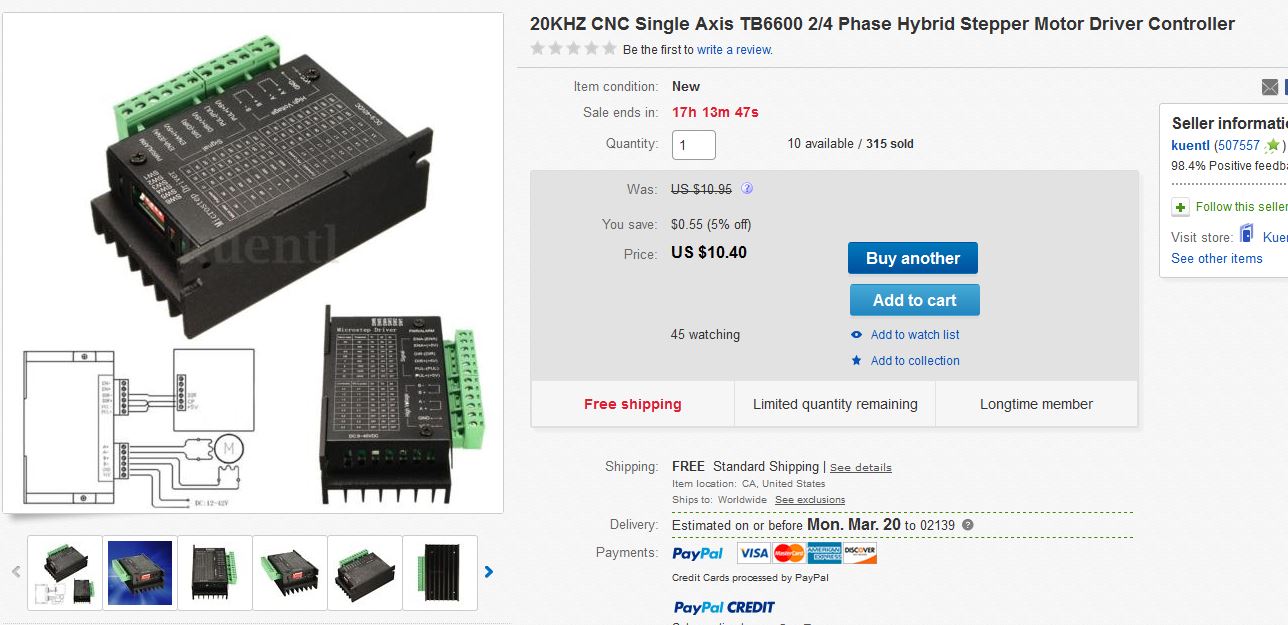 |
| Stepper Motor [Z axis] This stepper was pruchased new as well, i opted for a double-ended Nema 23 stepper so an encoder could be added in place for extra precision, and to close the control loop. |
1 | 29.50 [link] |
------ | [Link] | 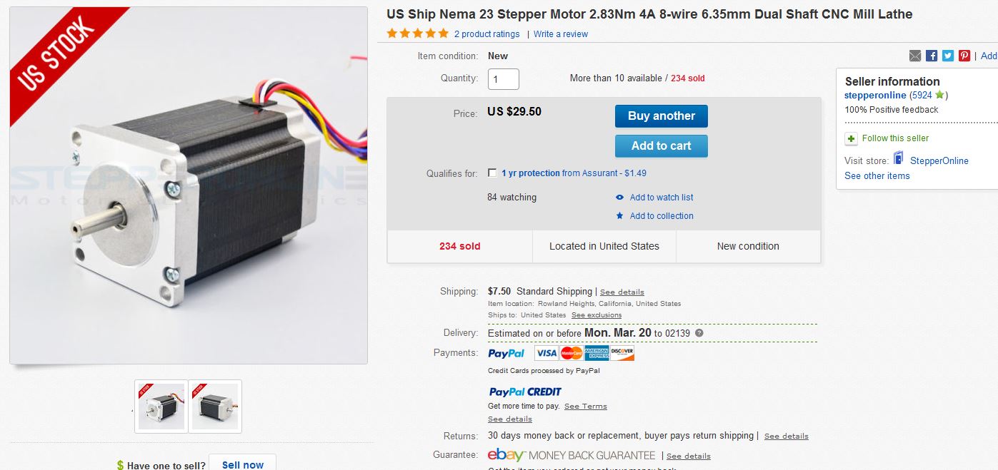 |
| Servo Drive [Z axis rotary] | 1 | 24.00 [link] |
------ | [Link] | 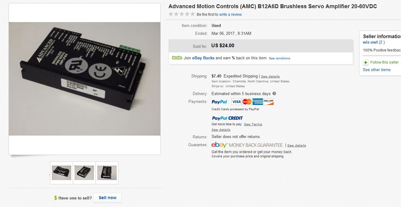 |
| Concrete drill bits | 2 | ------ | ------ | [Link] |  |
| 60A contactor Initially purchased a 40A contactor, but due to some hardware issues on my end, it was replaced by a 60A 2-pole contactor. |
1 | 20.00 | ------ | [Link] | 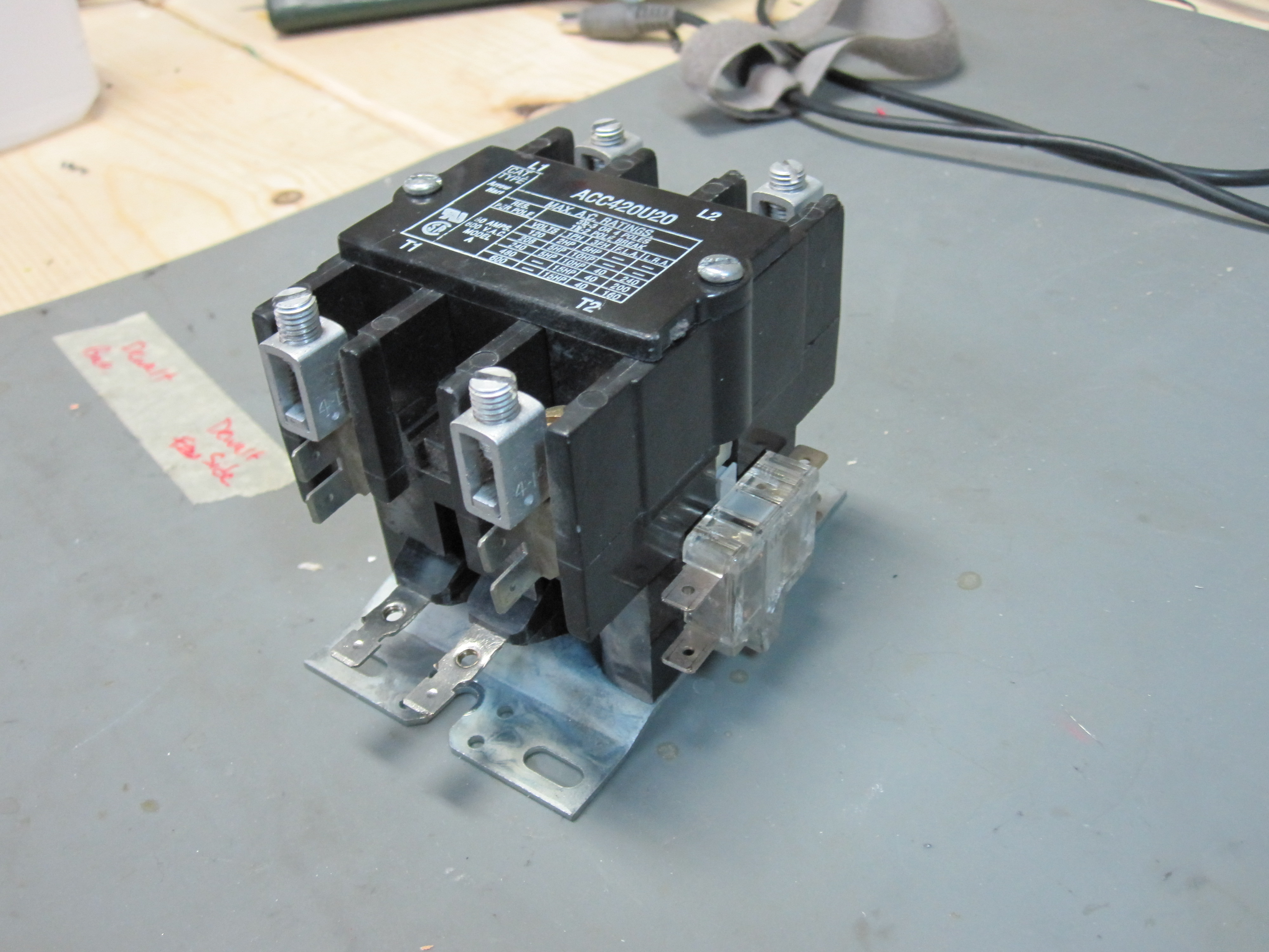 |
| 24VAC contactor control coil | 1 | 15.00 | ------- | N/A | 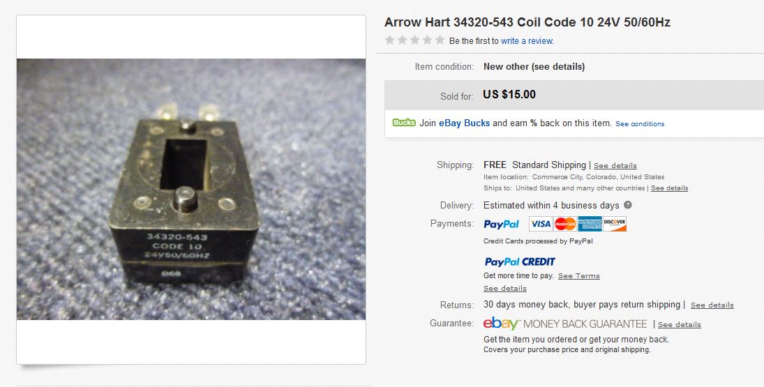 |
| Dell PC [Optiplex 755] | 1 | ------- | 105.40 [link] |
[Link] | |
| MESA 7I77 + 6I25 control card and breakout board | 1 | ------ | 347.52 | [Link] | 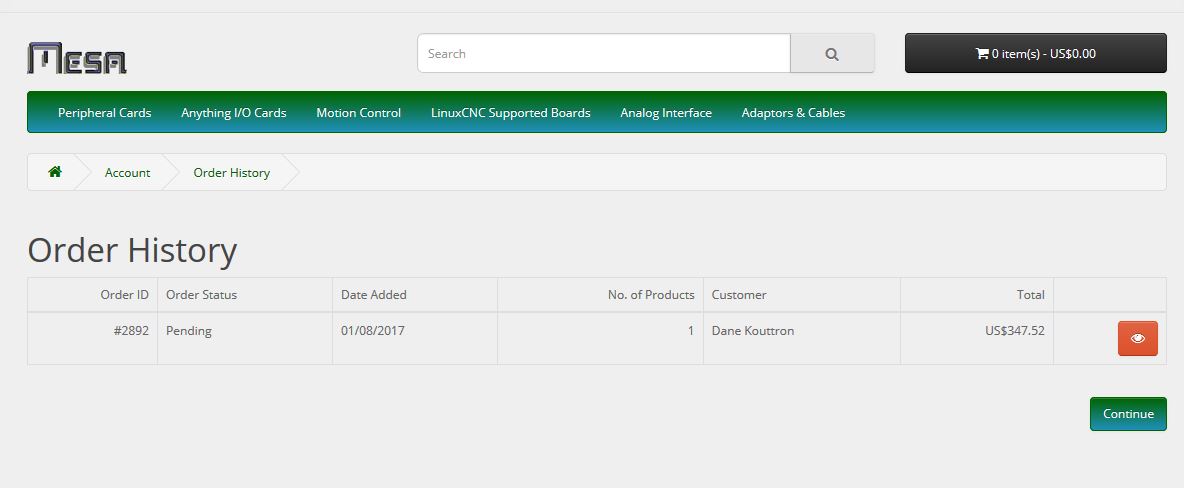 |
| DB25 Breakout | 1 | ----- | 9.59 | [Link] |  |
| Meanwell DR-120-24 AC [24V 5A Supply] | 1 | ----- | 33.99 | [Link] | 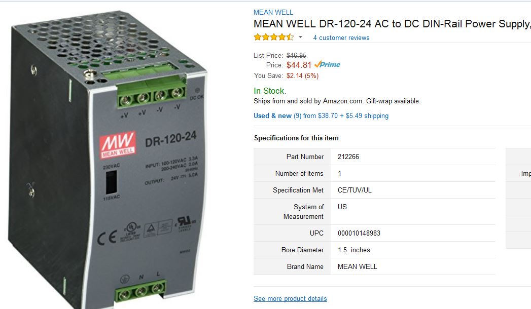 |
| Din Rail Relay Breakout | 1 | 19.49 | [Link] | 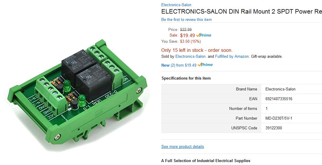 |
|
| Logitec F710 Wireless hand controller (low cost control pendant) | 1 | 25.99 | 49.99 [link] |
[Link] |  |
| Safety Laser beam break | 1 | 108.00 | [Link] |  |
| Downloads |
||
Paintbrush Holder Solidworks 2014 [link] STL file [link] |
Z Axis Assembly Solidworks 2014 [link] DXF Waterjet file [link] |
|
Painting Tray Solidworks 2014 [link] DXF file [link] |
Robot Arm Covers Solidworks 2014 [link] DXF file [link] |
50A Current Meter Holder
Solidworks 2014 [link] STL file [link] |
|
A QUICK NOTE ABOUT
ROBOT ART robotart.org is having a competition click here, check out robotart & vote! <requires facebook login, I know I know> |
|
Concluding Remarks:
The RobotArt competition and it’s rather skies-the-limit approach to a painting robot is phenomenal. It ties together a mix of kinematics and problem solving, with a lot of room for hardware and software solutions to problems that come up in painting. We took a perhaps more circuitous route than some in rescuing an old robot and bringing it back to life. Why start with a functioning robot when you can DIY? As a result, why not consider the robot itself, the kinematics behind it, a piece of art as well. Getting to know the robot, being able to dive deep into how and why it moves, and then, plotting how to paint given those constraints was incredibly rewarding.
Special thanks to all those who helped make this possible, the mighty Peter's pid loop taming, Birkels tablemaking, Sam's software and uncle Jume's aide in times of increased science.
If you have questions or comments, ask below or send over an email.
| Comments: |
|
HTML Comment Box
is loading comments...
|
Dane.Kouttron
Rensselaer Polytechnic
Institute
Electrical & Electrical
Power
631.978.1650