
Dane Kouttron
Project Started: 11/2022
Building a Bike Repair Stand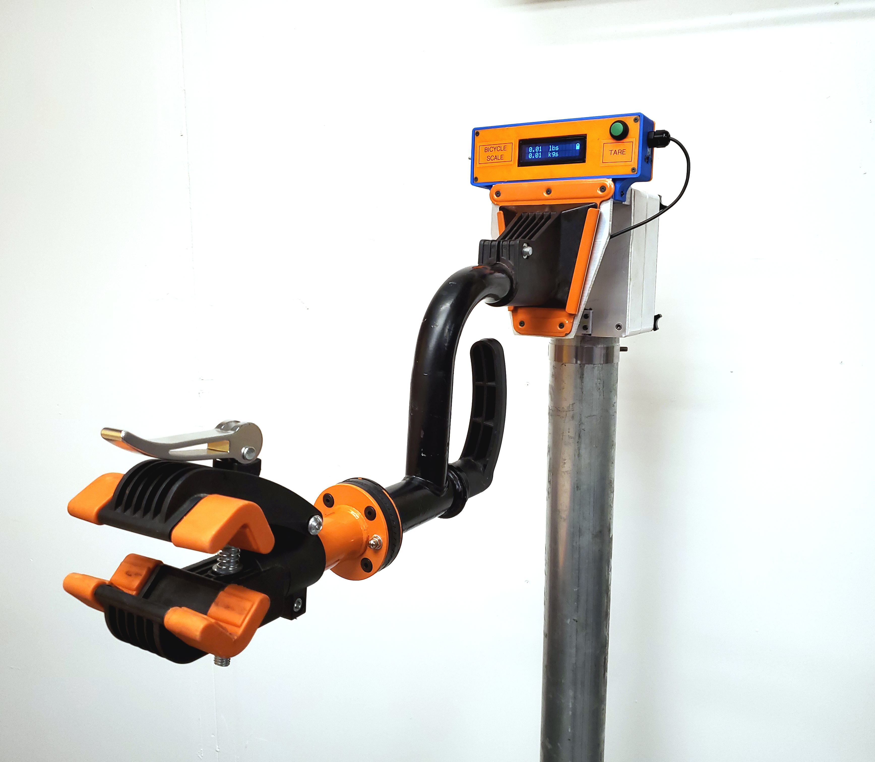
Do you have 'that bike' with the dubious derailleur that just needs some twiddling? Always wanted something to prop it up while you work on it? Did you know bike repair arms mysteriously became cheap? Cycles are great but incredibly awkward to work on without support. You end up leaning it against the wall, flipping it over to sit on the handlebars, munge up the shiftier and eventually knock it over. I've hung a bicycles from a ceiling chain hoist which worked well until I wanted to disconnect the battery pack and the whole thing swung about madly. Time to finally build a 'quick' bike repair standLike most projects, they grow legs. I ended up designing in a strain gauge and an integrated scale to keep track of how much mass could be removed from an e-bike build and hot damn it was incredibly helpful. |
||||||||||||||||||||||||||||||||||||||||||||||||||||||
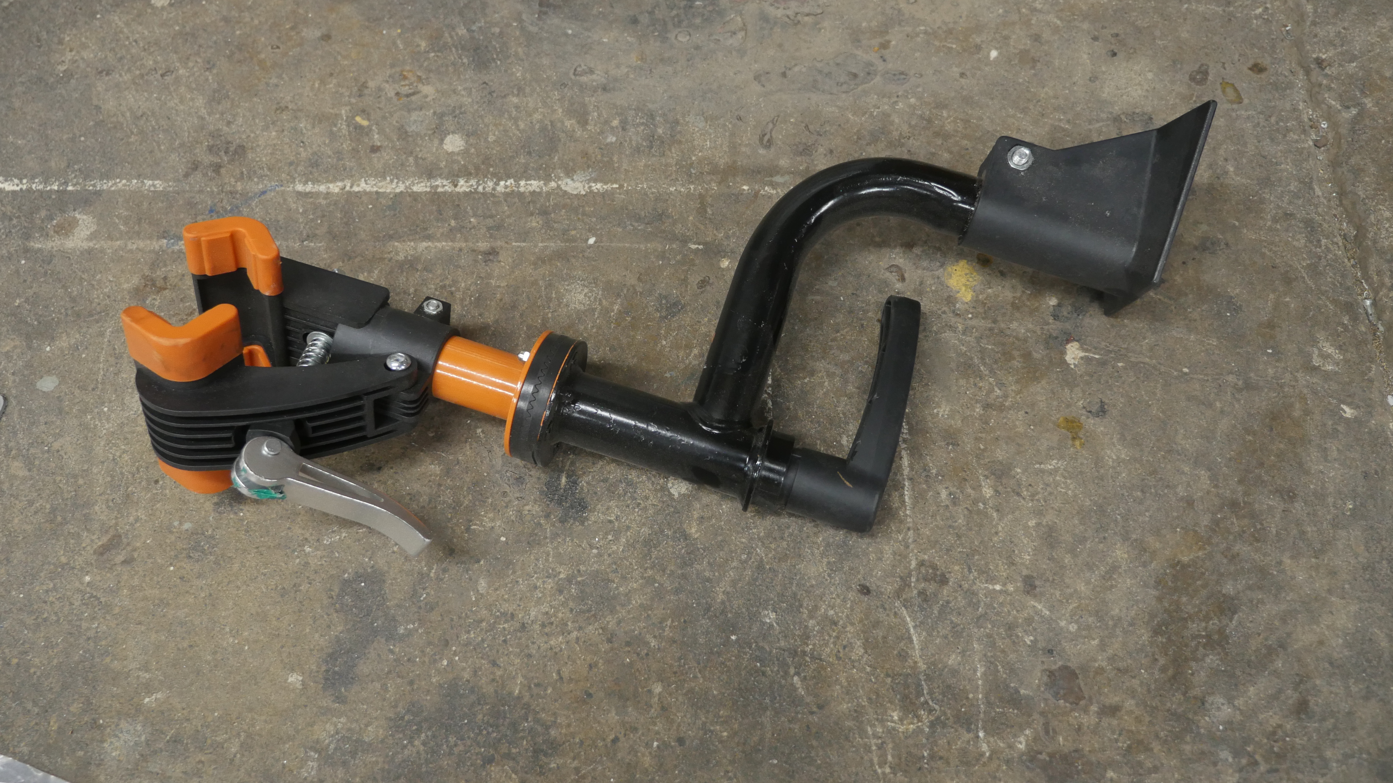
Bike Arm MountThis whole project started up after I found a fairly low-cost wall-mounted bike repair clamp. I had no idea these existed for so cheap. I've seen professional bike stands in shops for ages but I had never run across a budget repair clamp in the wild. As of 2022, these are presently 35 to 50 USD, which is actually incredibly reasonable. You end up with a split clamp, a 360 adjustable rotating mount and two gravity-held mounting brackets. Initially I was a bit suspect regarding the removable nature of the setup, but for the price it seemed worth a shot. Here's the gadget. This actually sat around for a few months while I was keeping an eye out for appropriate material for a stand / base. The one I got actually had chipped paint and rust and the seller ended up kindly offering a discount. Some sanding and spray-paint fixed that fairly quickly. 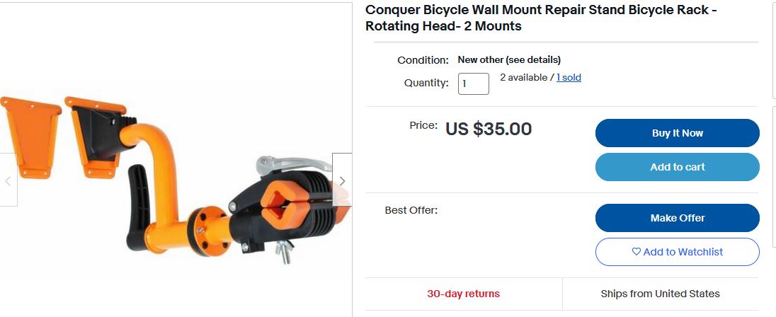
I'd rather mount this onto a moveable pole / platform than just bolt a plate to a wall, as it allows you to work from a both sides. I have some 3" OD plated steel pipe from some MIT crufting, and the base of an angle grinder stand, so why not throw together a quick adapter to allows this cheap wall-stand to become an adjustable height, uh, bike holder. Mating to the 3" pipe with a compression clamp will be somewhat time consuming to machine out of plastic, but really easy to 3d print, and given that the part will be under compression, a print should work fine. Here's the rough idea, in DANECAD. 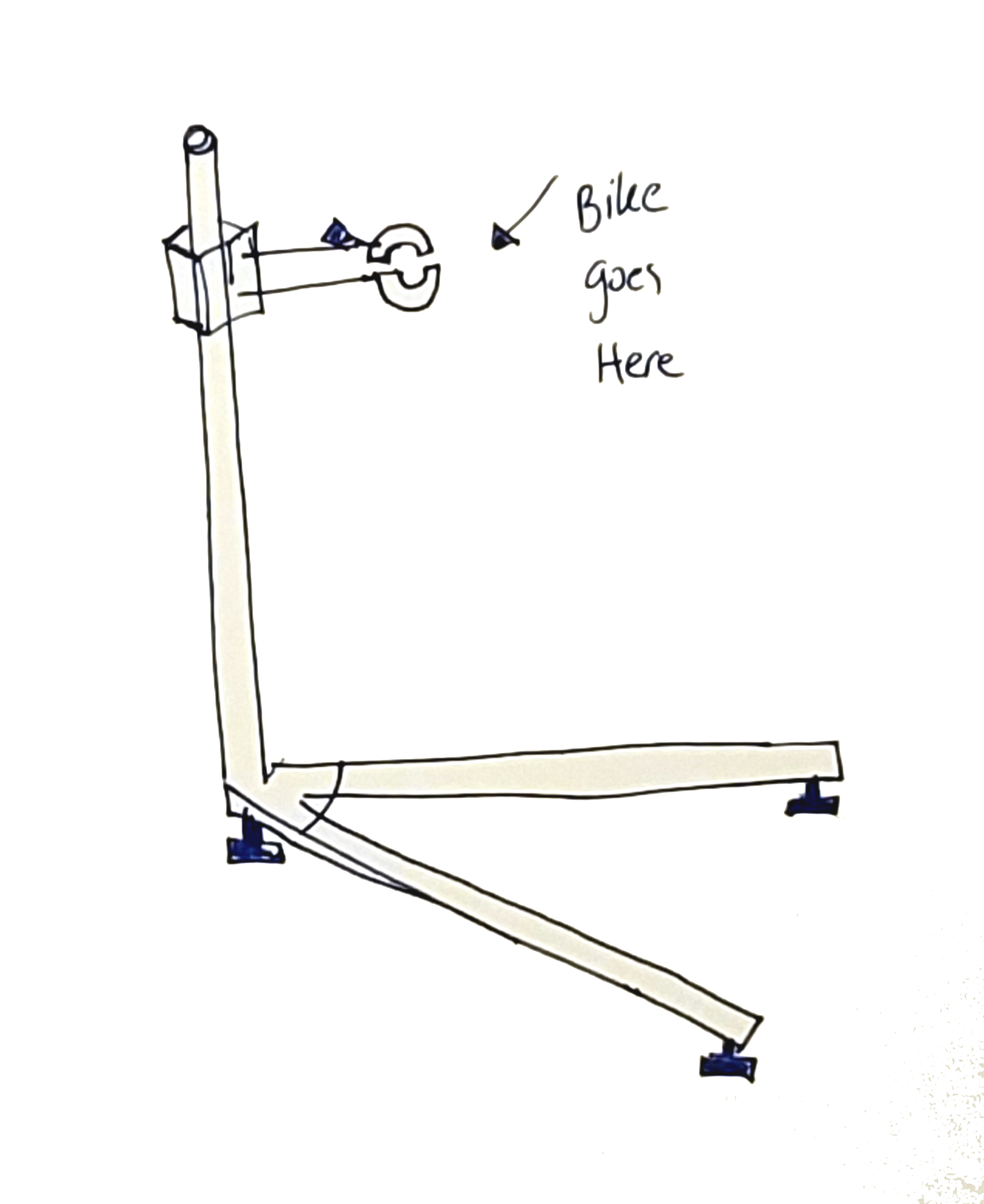
For a better idea of what I'm plotting, here's a rough 3d model. Its just some legs mounted to a base to make it portable, a slidey clamp to height adjust and some miscelaneous hardware to hold the bike arm to the slidey clamp. The legs extend underneath the bike to provide stability, as the bike arm sticks out a fair distance to provide space to work from either side. The bicycle model is from grabcad [link], I really liked the accuracy of the model, I ride ~medium sized 26" ish so this was perfect. The printed parts will take a bit to print as the 3" diameter pipe is fairly large and picking up part of the bolt pattern of the adapter plate results in something ~4 hours-ish to print. Here's a rough plot of the printed parts sandwiched between aluminum plates, with a rough outline of the bike adapter bracket. The actual force on the print is spread over a large area and reinforced with metal backing plates. Things are starting to come together, using two of the bike mounting plate holes as guides defined how big the clamp was. The bike arm mounting plate attaches toan aluminum plate in three spots. I drilled and tapped the two bottom holes and the top hole for some short 6mm long M3 flat-head screws. After test fitment I opted to use 'medium' strength thread-locked to keep them in place. The four perimeter screws are not tapped to allow very long machine screws to make it to the back of the clamp. With the 2-part sliding clamp printed, I wanted to make sure things actually fit. At the time I had screws that were 'almost' long enough to reach thru the parts and make it to the back plate. I opted to change the design a bit to allow thumb-screws for tightening / loosening, so adjusting the height does not require a tool. This is a welded-seam pipe so its not a fantastic surface, it surprisingly did not make much of a difference with the clamp loosened. I may go for a cam-lock style lock instead of the four thumbscrews but they do seem to work fairly well. Its always nice when your 3d printed curvature actually dimensionally matches the CAD. As the clamp is holding up the bike and everything else thin aluminum plates (1/8") sandwich the print together. Initially i plotted to use thermal inserts and have the plastic take the load, but using the plates to keep the whole surface of the print under compression is remarkably more structurally sound. This prevents the screws used to hold the clamp together from being stress concentrates and also lets me add some tapped holes for the quick-release plate to connect to. Assembling The StandWith the vertical mount coming together it was time to sort out the cantilevered feet. I wanted this bike stand to hold up a chonky e-bike, so the legs would need to stick out fairly far. Some quick CAD and a bit of static force diagram sketches I had a reasonable separation angle. I grabbed some 1/8" scrap flat stock and traced out cut lines from a 1:1 printed paper diagram, and then cut the part using a small craftsman bandsaw. Using the cutout, I traced the hole pattern from the scrapped uni-strut.. and neglected to center punch starter spots. In retrospect a step drill would have probably been a better choice for these holes. Its also unclear if this was actually 6061 aluminum, it seemed like it could have been a less-structural 5000' series plate stock. Note how much material was leftover from drill-outs, this is not normal behavior for 6 series aluminum plate stock. The hole quality was somewhat mediocre so I opted to clean it up with a chamfering tool. This is generally used for recessing flat head screws or equivalent, however it works fairly well for cleaning up the holes on either side of the plate-stock. Next up is to feed some bolts thru the bottom and lock the uni-strut in place, as the uni-strut holes are fairly large, fender washers were used to allow the nuts to be able to clamp the strut to the platestock. Parts are attaching from both sides so I opted to use uni-strut nuts to hold in the front facing part of the legs to the uni-strut, while the rear plate is attached to the bottom. There was some logic behind this, as it gives the rear rubberized foot an attachment point closer to the ground. Admittedly the thickness of the lower plate could have contributed more here as the bolt clamping force on the back causes the lower plate to bend. Next up: Attaching the rear foot. I opted to prop the stand up temporarily on some 2" wide masking tape rolls. The rubber foot with studded post is in the mechanical bill of materials [link]. One of the advantages of the taller studded post was using nuts underneath to adjust the final height. They are surprisingly squishy, I think these may be intended more for compressor vibration mounts. The front facing feet are just bolted in place, with the rubber part resting on the base of the uni-strut. This does leave a bit of stud sticking out but that can be ground off later. Otherwise the base sits on the uni-strut and everything's easy to keep level. Finally I ground off the remaining studs so they were less of a tripping hazard. The base to pole mount is actually more of a friction fit, two hex bolts thread into the cast base and compress against the 3" pipe. As this is somewhat thin-walled it does kink the pipe a bit after a point. To counter this i ended up putting in some 2.85" wood 3/4 plywood plugs so that the screws don't just compress in the tube. Here's the final-ish contraption, a little goofy, a bit heavy but its feet fit under a lab bench and the adjustable head allows it to hide against the wall when not in use. I hung underneath it to see how well it would withstand 80kg and impressively it was fine. It does need a bit of a paint job on the bottom, but otherwise fairly happy with this 'mostly surplus parts' bike stand. 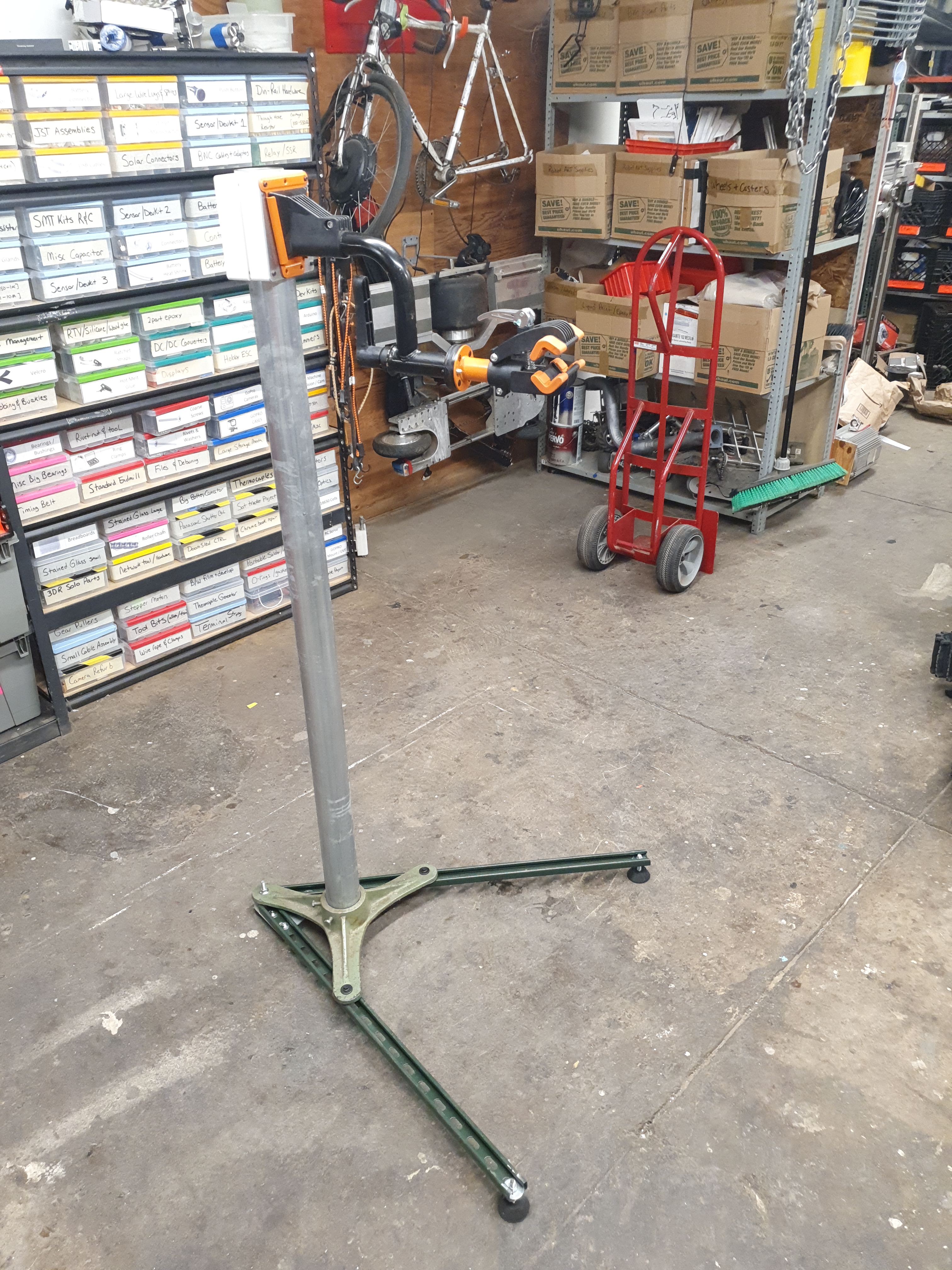
I grabbed the heaviest bike I've built, a 1.5kw front hub, 400wh rear battery-d jason-troller powered behemoth. Not actually sure how much it weighs, but its fairly unwieldy. The stand was remarkably stable. Immediately I knew what I wanted to do next: (�_�) Add An Integrated Bike Scale (�_�)It would be pretty interesting to modify the head-stock to make it indicate mass. This would be incredibly useful when doing a 'build from scratch' bike project. I thought about adding three strain gauges on the feet and integrating them but that does add a lot of wiring to the ground and I suspect this may get a lot of abuse. 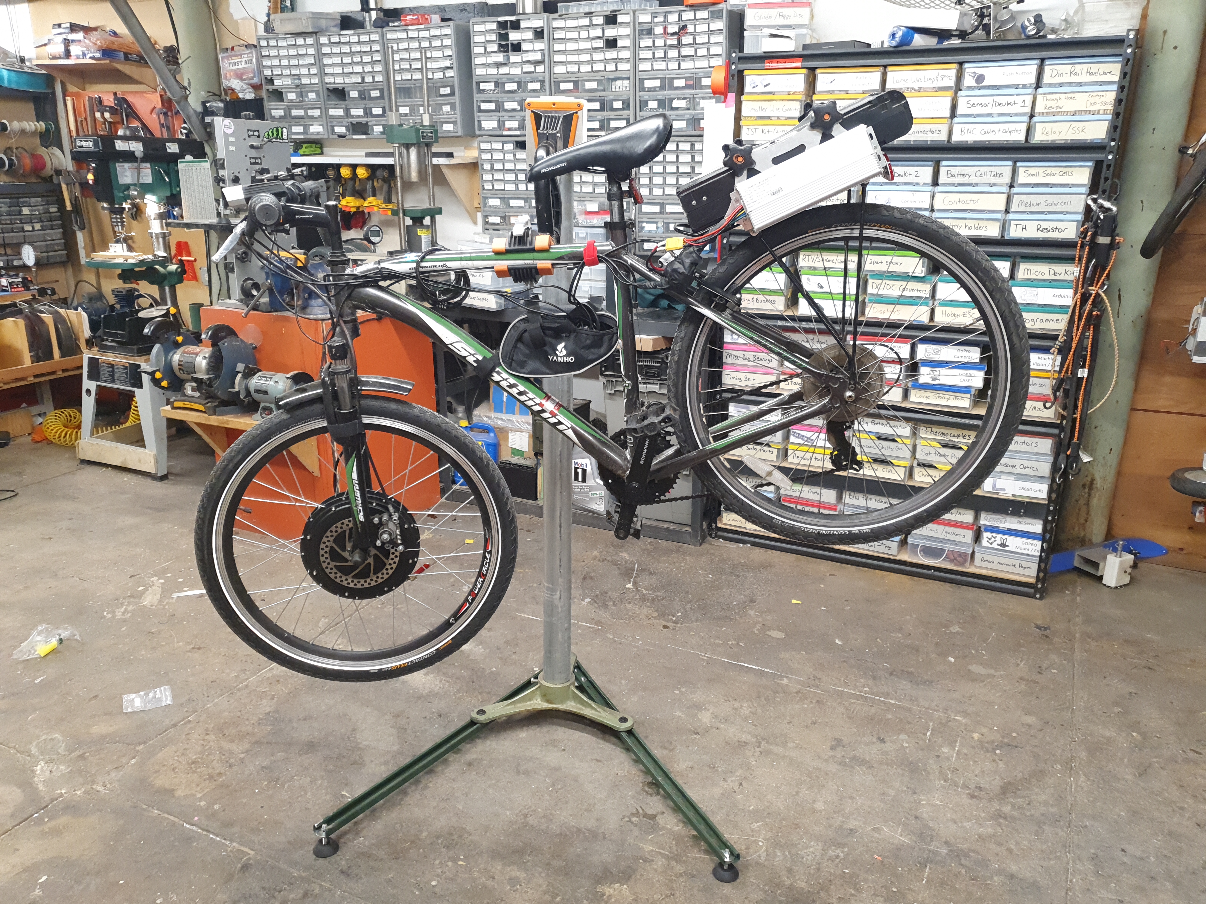
Plotting adding a 'scale'
Ok, hypothetically how would I add a 'scale' to this contraption. 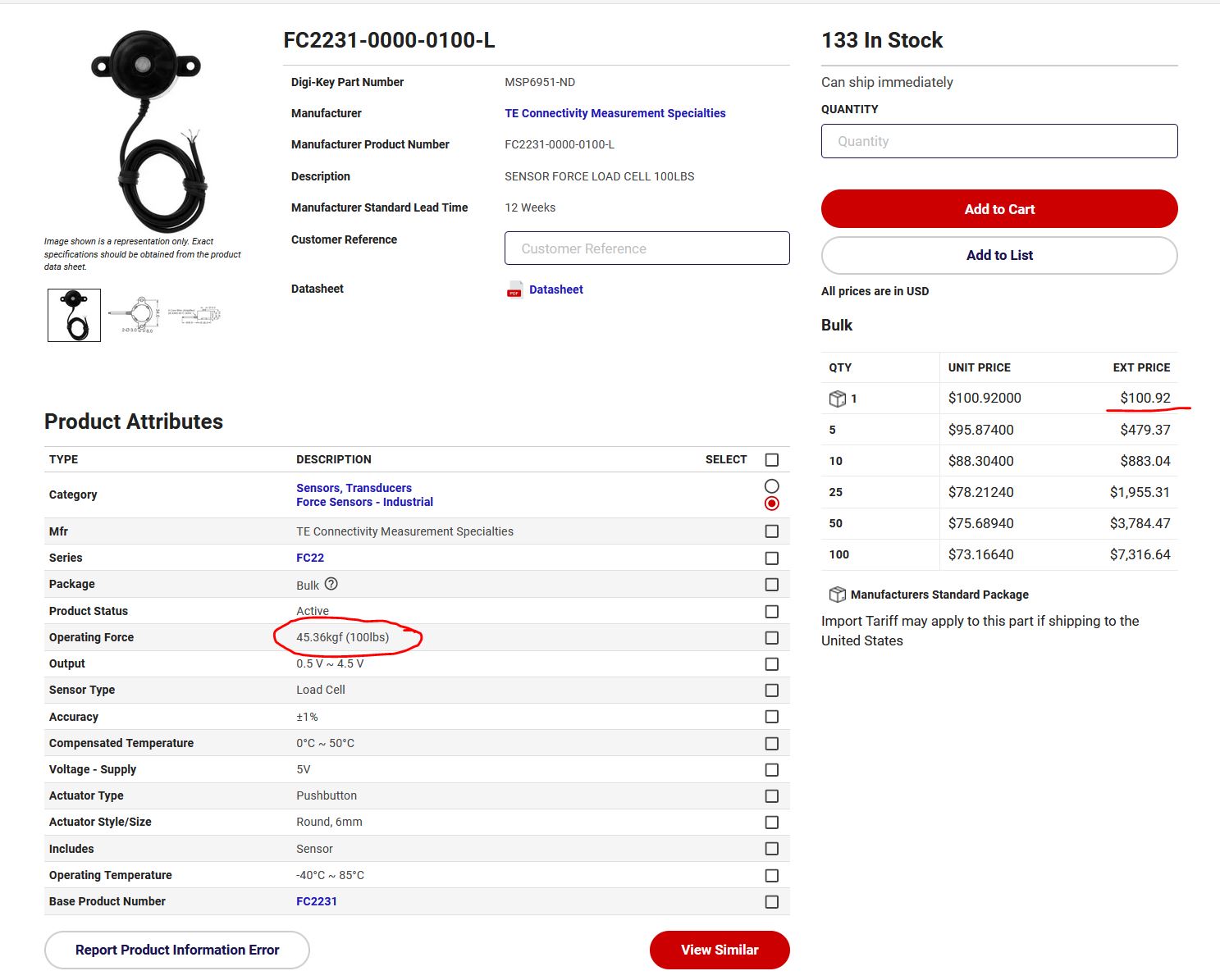
This sensor got my attention [link], as it has its own pre-amp, doesn't require 10V bias and can measure 100lbs. It is only defined in one axis, so it has no mechanism to constrain the plate-on-hinge. Reading from this sensor only requires a single ADC channel, with no external hardware which is so nice. Mechanically, I could actually sneak in a tapped M3 hole here to constrain everything, but modifying a ~100 USD sensor is a bit of blasphemy. 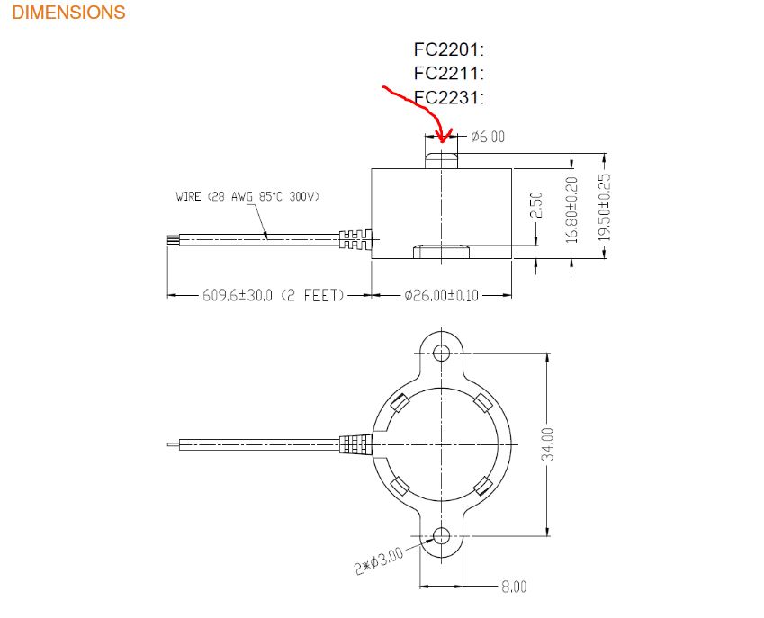
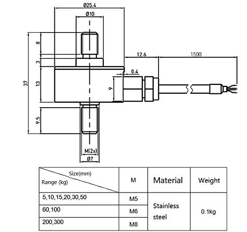
Let's see what Amazon's got. This is a bit of a better fit [link], it's 50kg rated and has studs on either end. Its not totally clear if the dimensions are accurate as the size of the threaded stud is called out but also varies from M5 to M8. This will also require a strain gauge amplifier, which isn't terrible but is an extra component. Ideally all the force from the bike holder arm would get routed linearly into the studded strain gauge, which gets amplified and digitized. A small arduino wakes up and reads this and displays it on a character display or maybe a small OLED. I'm going to need at least a 'tare' button, so I can zero the scale and an on-off switch. I think a small 1S 18650 pack with a 5v Boost / USB charger should work really well here, along with a power switch in-line with the single 18650. 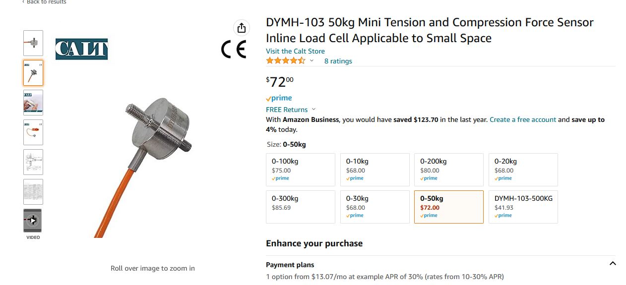
Project
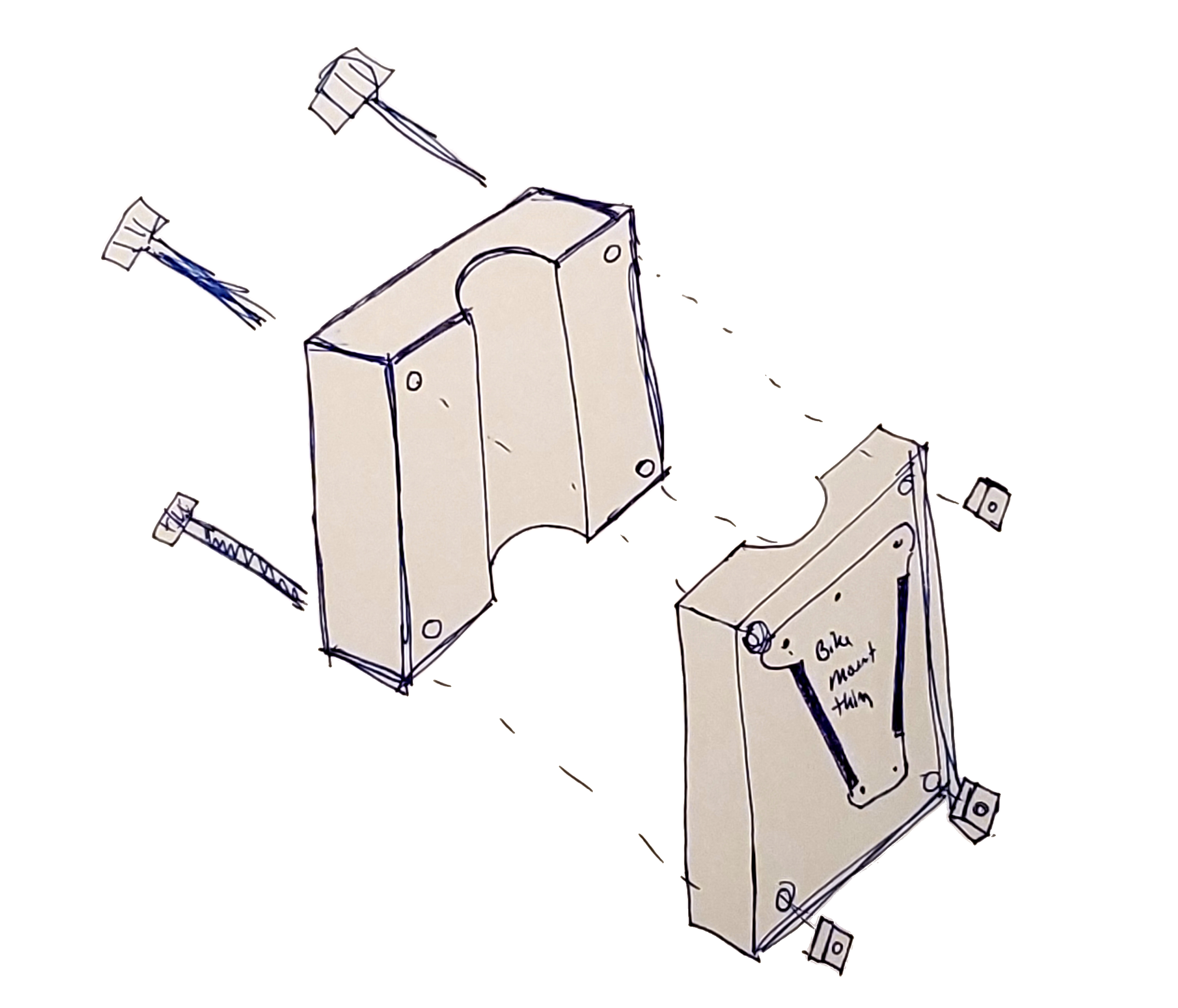
'lets complicate something that already works' is a go for launch  Next up is picking a character display. While I like OLED displays all of the ones I've run across are fairly small and this is something I'd like to view from a bit further away than 1ft. I'm fairly sure we can solve the mechanical parts of this project while we wait for Digikey and Amazon. We know that we want all of the arm's force to translate into the strain gauge, and we know that the deflection of the sensor is really small. On the plus side, this just involves making a second mount, the initial one can stay as it is for the time being. Given that the deformation is small, using somewhat thicker plates for the hinge would probably make more sense. I think the wall mount actually came with two wall-plates, so assuming I can find the other one I could make a completely separate assembly. 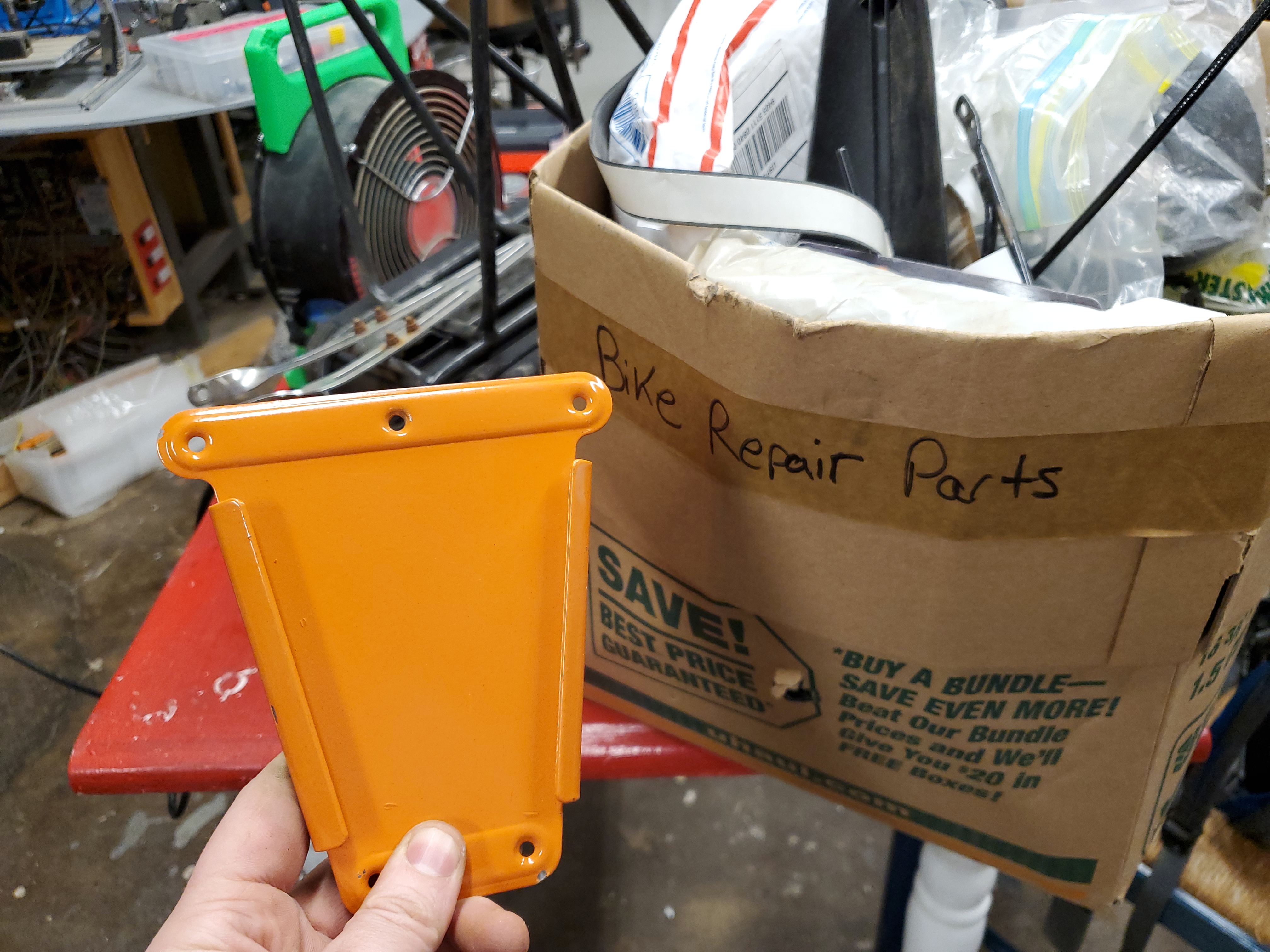
That one time something is actually hiding where it would make sense to be hiding, A very worn down 'Bike Repair Parts' U-Haul box. Armed with a spare mounting plate, its time to make some rough 3D models. Let's get dimensions of the whole arm-thing and jot down a force diagram. Accurate dimensions are not really required here as known masses can be added to the bike hanging end to calibrate against. Dimensions do help for figuring out what range of a strain gauge to use, given that there's a lever arm here a 20kg bike may apply 3-4X that force to the strain gauge based on these dimensions. The geometry of the twisty arm doesn't have any effect here, we just care about the distance offset from the attachment point to the bike grabber part. Dimensions below are in inches. 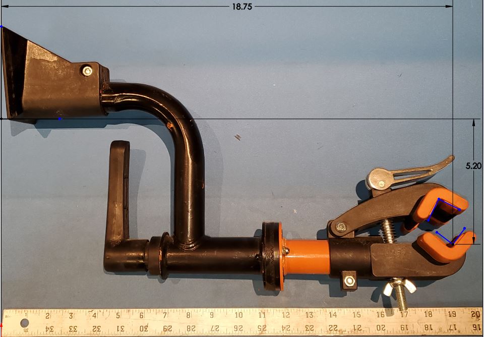
Scale Electronics: Sorting out the 'rough requirements'
Before 'just gluing parts together' its always a good idea to put together a basic block diagram. Block diagrams do not have to be incredibly detailed, but just have enough components to ensure that nothing is missing. For instance below, there's a toggle switch between the battery and the USB battery charger board. When toggled off, the battery is disconnected from the system and nothing receives power, so there's no background quiescent draw. Block diagramming also lets you see errors in your initial plotting, for instance The external USB port is only able to charge the battery, not program the mircocontroller. This is fine, as its a scale and its unlikely that multiple firmware changes are necessary. Another note is the micro-controller has no way to see the battery state of charge / voltage, so this will work until it runs out of battery and then abruptly shuts off. Again not the end of the world, but only visible after a first pass block diagram. 
First Pass Bill of Materials [Electronics + Load Cell]Some parts are excluded as generics, nominally 22 gauge interconnect wire, solder, heat-shrink. Prices are listed without shipping.
Oof that is a bit pricey for a scale and a readout. Or is it?There's a few amazon-able options that range from 60-100$$ and plenty of eBay options that are ~50$$, it would however be difficult to add these and still have the bike arm holder 'constrained' and not flopping about. It may be interesting to purchase a cheaper eBay scale, extract the strain gauge and then adapt it to the lever-style design. This should shave some of the price off, especially if I can wire it back in to the original readout (with the gauge remotely connected), but it would require some intermediate conversion, as the scale is used in a lever-arm in its present configuration. That may be a bit more effort than it seems at first glance. 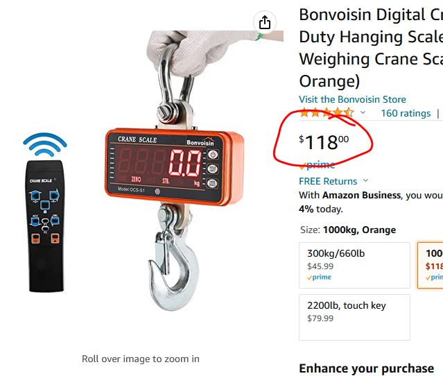
I did have some thoughts about the block diagram. If the USB Battery charger board has a nonswapped ground (ie batt - and gnd are connected) its possible to wire over a single line directly from the switched 18650 into a micro ADC. Given that the arduino nano is 5V logic and the ADC is 5v tolerant the battery itself is bounded to operate between 4.2 (charged) to 3v (discharged). Whats nice is no parasitic resistor divider is required. Lets update the block diagram once we check in on that USB battery charger schematic. The huge bonus of using sparkfun boards is, schematics are available. The amazon overseas clones are cheaper but I can check the SparkFun parts before they actually show up. The USB-charger / boost converter is here [link] Lets check the schematic: 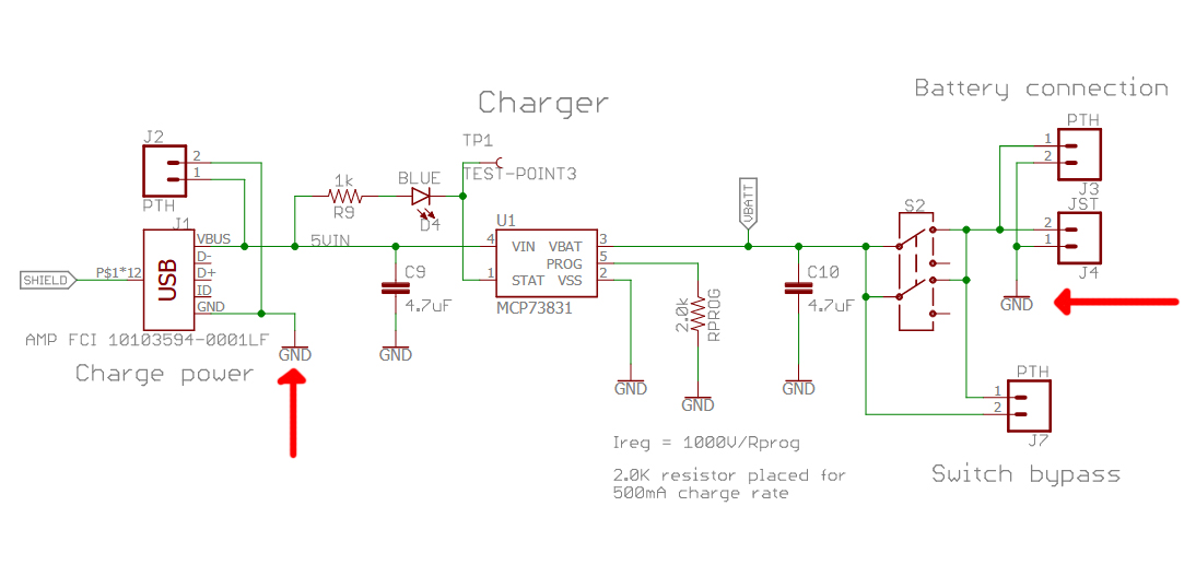
Nice, same ground on either side, so we can pass the switched VBatt directly to the micro's ADC. Another interesting part is, we know that the PAM2401 switching regulator used to boost the VBatt to 5v shuts down below 3V, so we don't need a UVP / under voltage protection. We don't need a power on indicator as the LCD will do that for us (it is backlit). Ok lets mechanically lay out all the parts we're plotting on using. With the parts in hand, mechanical layout is quick. The goal is to get the important dimensions down (mounting holes, boundaries of parts, etc). Scale Mechanicals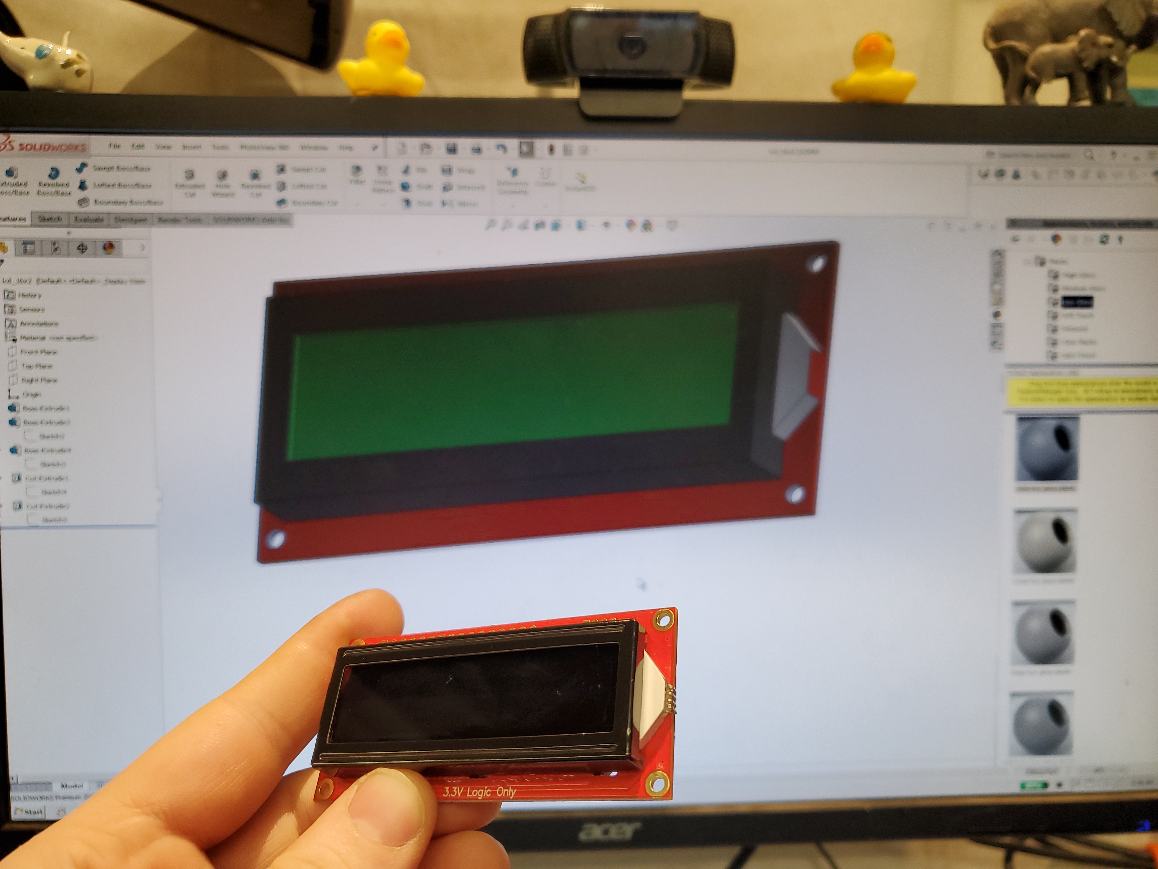
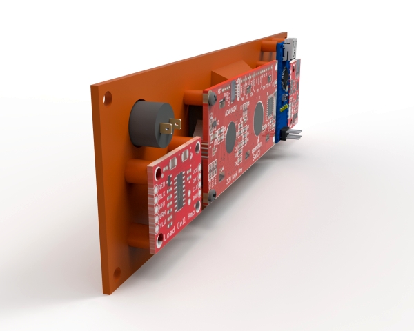
After some caliper rodeo, I generated rough models for each part. The Arduino nano is so ubiquitous, I was able to use a model from Grabcad [link to model]. I opted for some changes from the block diagram. I decided that it would be good to be able to re-program this without taking it apart, so i made the arduino mini-usb accessible from the top of the 'enclosure'. Each board has an associated printed standoff that gets a thermal insert. As all of these parts are hyper-small I'm stuck with M2 or M2.5 for screws and thermal inserts. While this could have been 'dense-er' if I had stacked boards, but a flat layout seems cleaner and way easier to assemble. Given that the bike-stand holder itself is ~5" wide, I could make the assembly match the width without it looking too peculiar. A render of the front part of the enclosure is visible below. 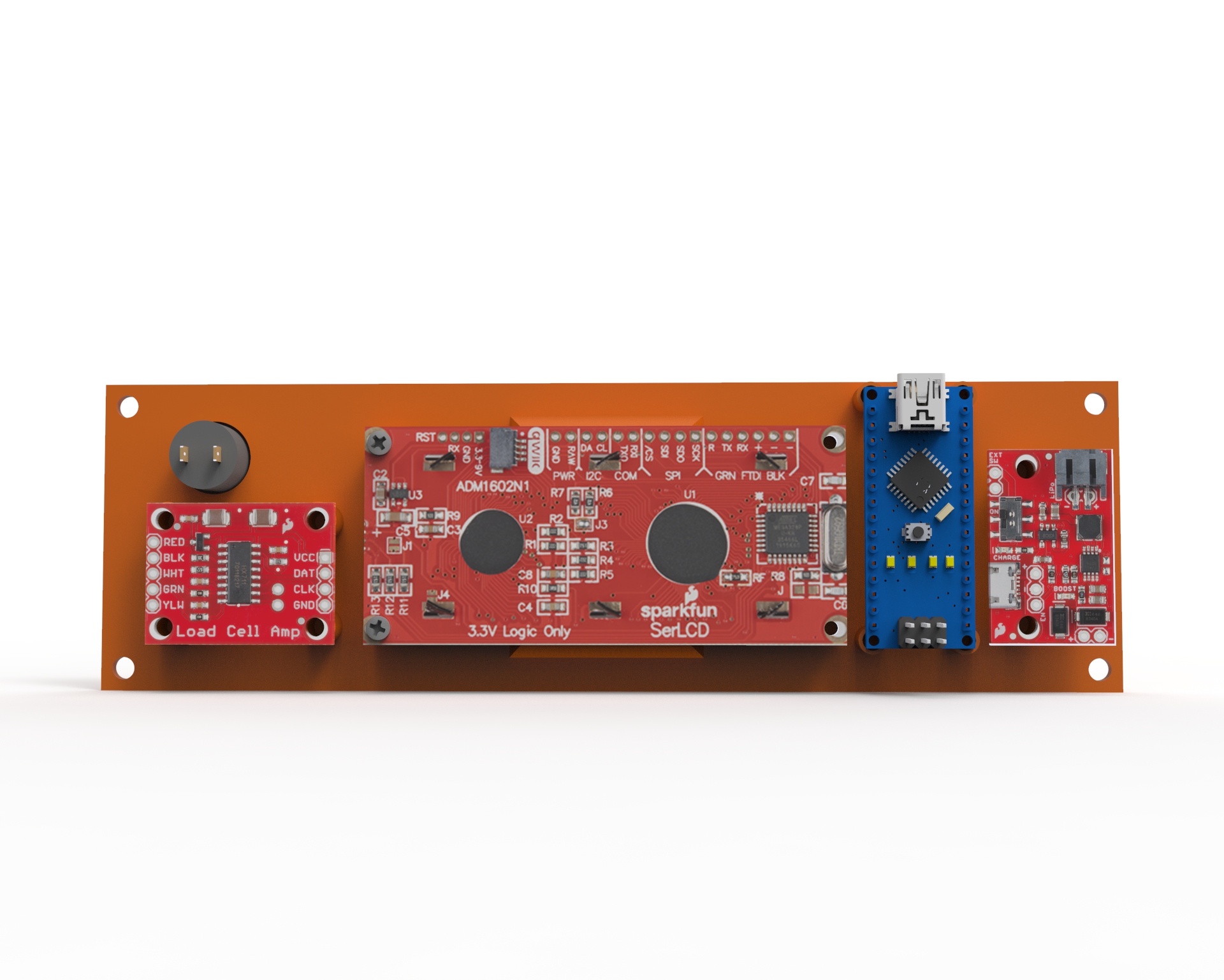
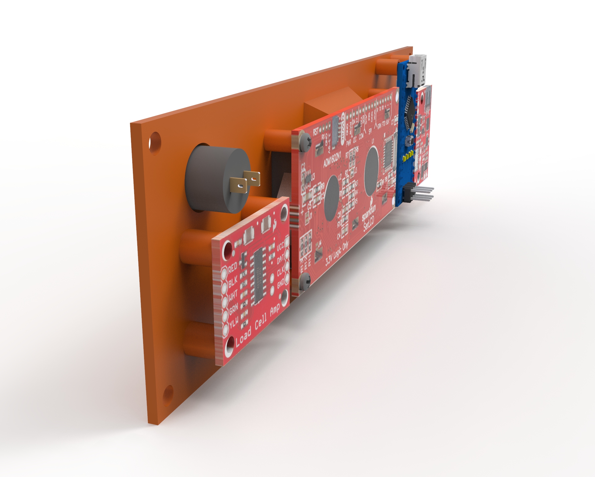
Here's the front panel piped into Keyshot. Interestingly Keyshot doesn't quite import 'decals' from Solidworks, so they end up needing to be re-attached to the model surfaces. Not the end of the world but took a bit to sort out exactly how to do that. The text is inlay-ed into the 3d print. I've had *some* success filling in inlay-ed text with paint, but it is somewhat messy. If the final print doesn't show the text well I may opt for some light painting. Ive been wanting to try masking the area nearby and just hitting the part with a light dusting of spray-paint, instead of acrylic paint and a syringe. Ok we have a block diagram, the solid model slowly being created in a 3d Printer. Lets sort out the actual schematic. Updates to the block diagram are shown below, nothing major, just a way to sense the 18650 voltage and also a logic input from the external USB connection. I should be able to put together a small battery % display and also indicate when its charging with the addition of those two wires. 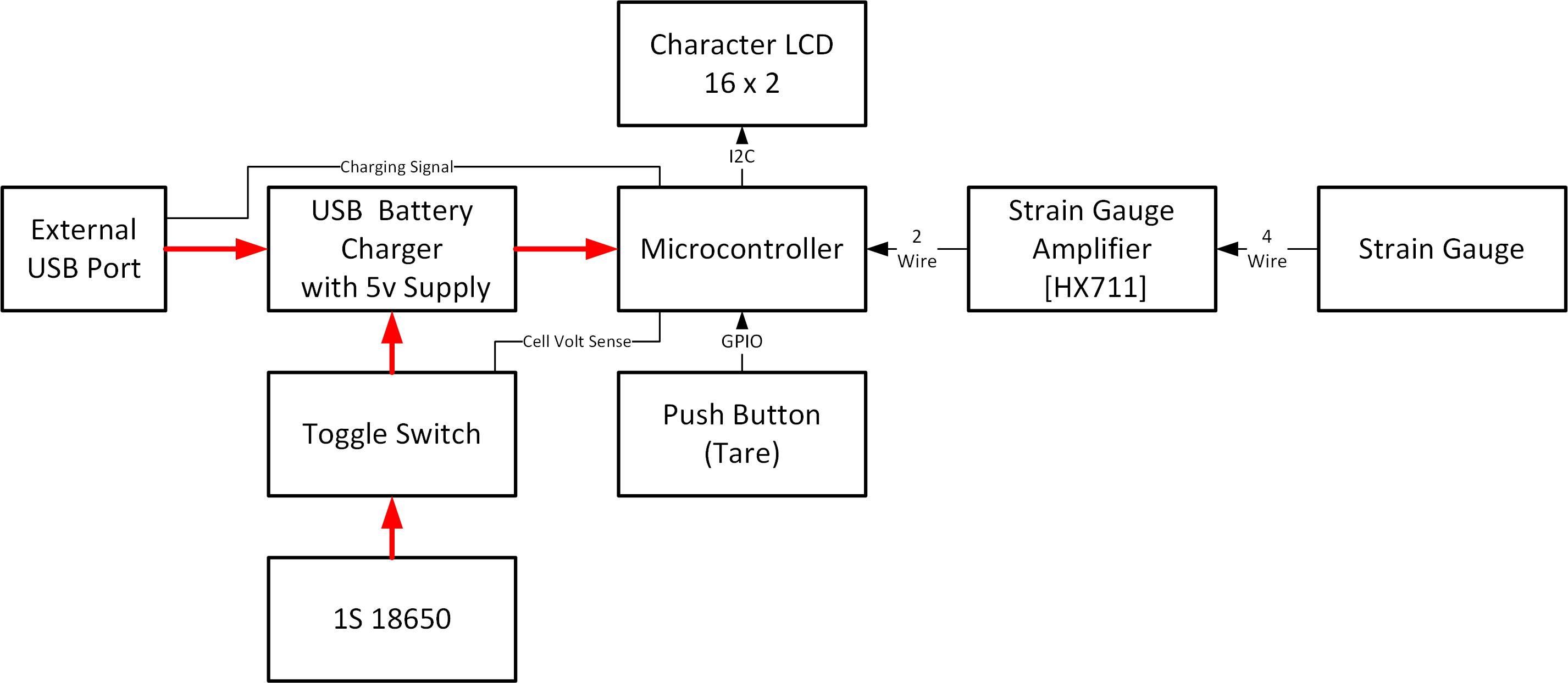
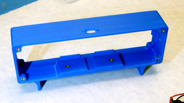
With the schematic handy and the rear enclosure just about done (ahem the 3d printer is free for more printing), lets design the rear part of the enclosure. The only major parts we need to be aware of is a cable gland for the strain gauge an on-off toggle switch and a panel-mount USB-C port for charging. I'd like the front panel to sit in the enclosure and attach with the 4 perimeter screws into threaded thermal inserts. I printed the front part of the enclosure out of orange, hopefully I have a bit more blue available for the outside as it contrasts well. I tried 'saving time' and making a render using Solidworks animation, but it looks so terrible in comparison to Keyshot, so here's everything re-imported into Keyshot and rendered together. A 600 x ~400px animation is a 10min CPU job on an older 2 X 2.1ghz 16 core Xeon, but it does look great in comparison. Note the back of the model is open, eventually a laser-cut sheet will cover it up (next time I get access to a laser cutter). To cover the in-laid text, I wanted to try spray painting. It *should* be quicker than acrylic paint, and if I mask off the area the leftover spray-paint should sand off without much of an issue. This sounds good but there's probably a gremlin hiding here. I masked off the areas outside of the inlay-ed text with blue painters tape and used some matte black spray-paint. 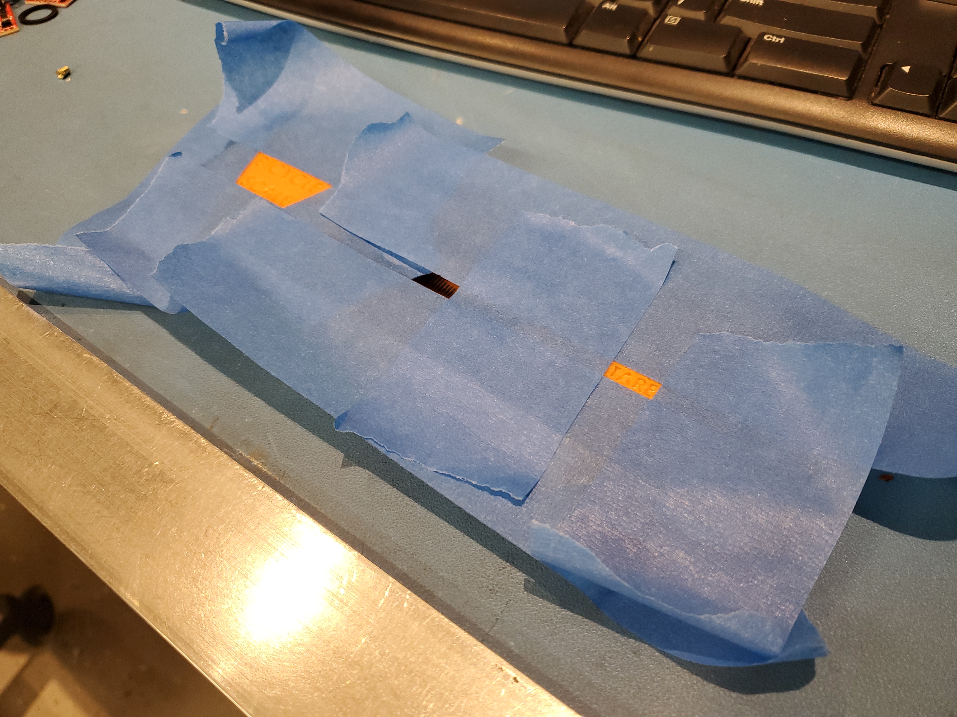
Spraypaint was a mistake. Unlike chunky acrylic paint, the spray paint solvent seemed to aide it in finding the seams of the 3d print and sticking into the seams. This was after ~an hour of sanding off the remaining paint. It looks pretty mediocre. In retrospect a better option may have been actually clear-coating the part with clear spray paint (to fill in the voids), waiting for it to set, then masking off and painting with black paint. This probably would have made this less messy, instead the printing artifacts are really brought out and visible. I could re-print this and go for the clear coat first approach, but i have another idea. 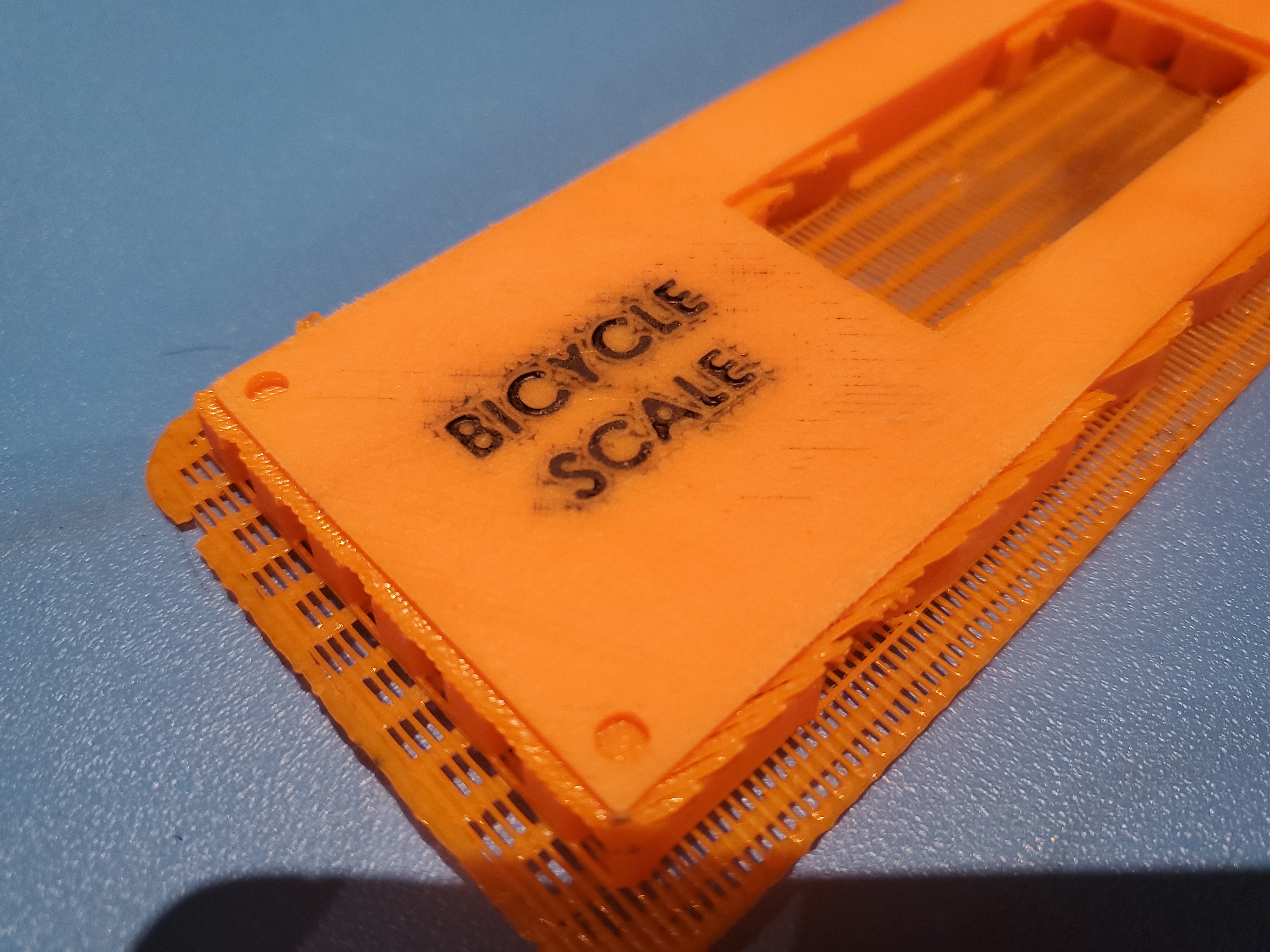
I have some orange 1" wide label maker tape and while its not as spiffy as inlaid text, it doesn't look too bad. I sprayed a layer of clear coat on top of the print and labels, to help the label stay in place / not de-laminate off. It also seemed to make the heavily sanded down orange PLA look a bit more reasonable. Its not fantastic but I'm ok with how it turned out. 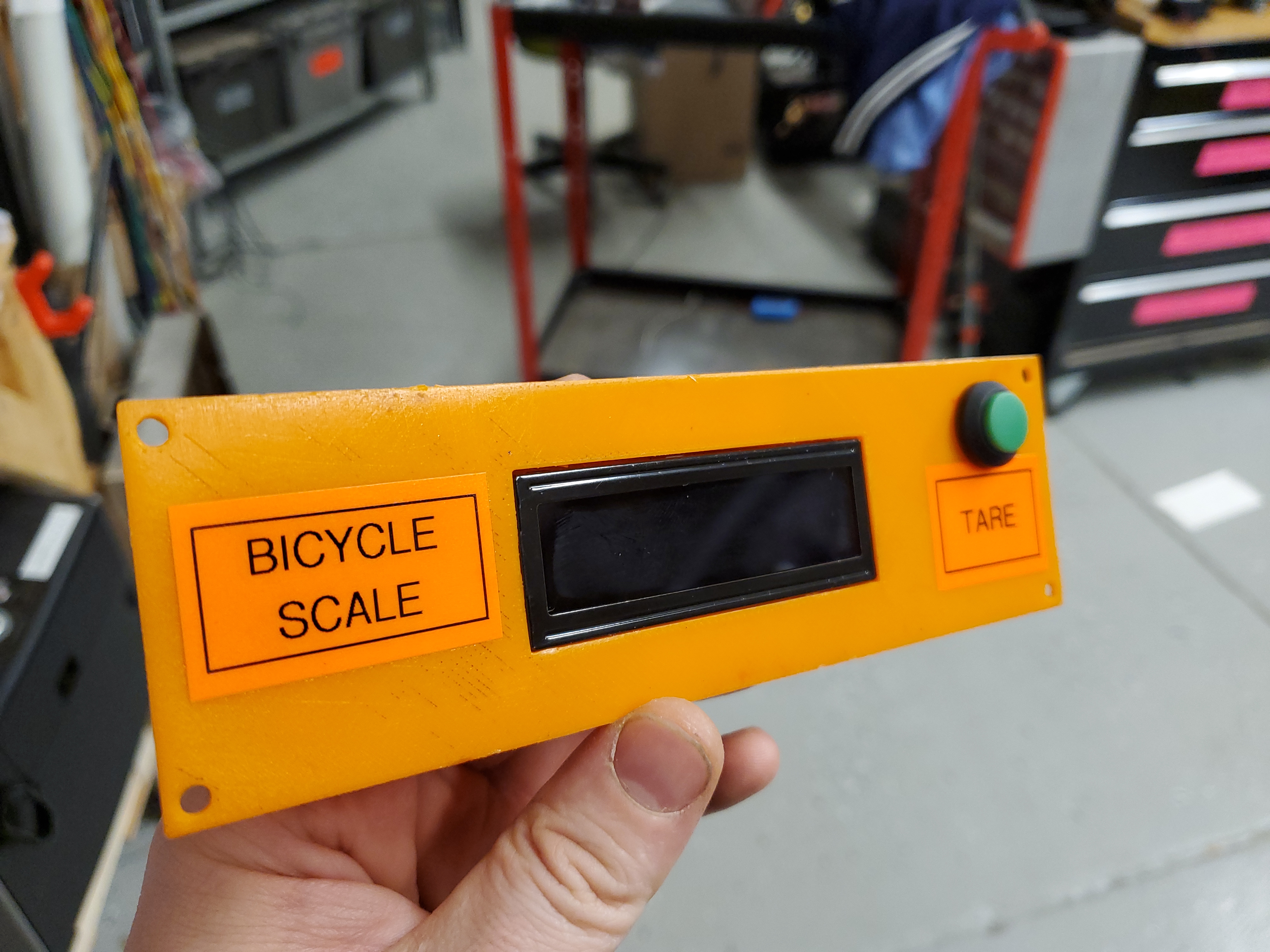
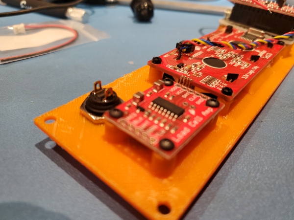
Time to add in the thermal inserts that allow the small pcbs to attach to the front panel. These are all M2.5, mostly driven by the hole size used on most of the PCB's. The knockoff arduino nano however ended up using size *impossibly smol* screws, which didn't match with the cad model, so I opted for some double-sided tape and grumbling. My tried and true tactic for 'close enough' thermal inserts is to thread the insert onto a screw, with the screw going all the way thru the insert to prevent plastic from finding its way into the threads, then heating up the screw insert with a hot air rework station. After 30+ seconds I use a small stubby pair of pliers to smush it into a 3d printed part and it just works The 30 second rule is not really a rule as it physically takes ages to heat up an M6 thermal insert + bolt whereas an M2 / M2.5 is nearly instantaneous. These were all non-through print inserts so i made sure not to over insert the thermal insert as I really didn't want to have to re-make the front panel due to screw heads poking through. Populating the parts was painfree. The standoffs printed into the front panel served two purposes, to allow for wires to pass underneath the pcb modules and well, the standoffs were 0.25" tall and I wasn't going to make the face-plate that thick. The M2 / M2.5 button head screws zipped into place and it was time for soldering. 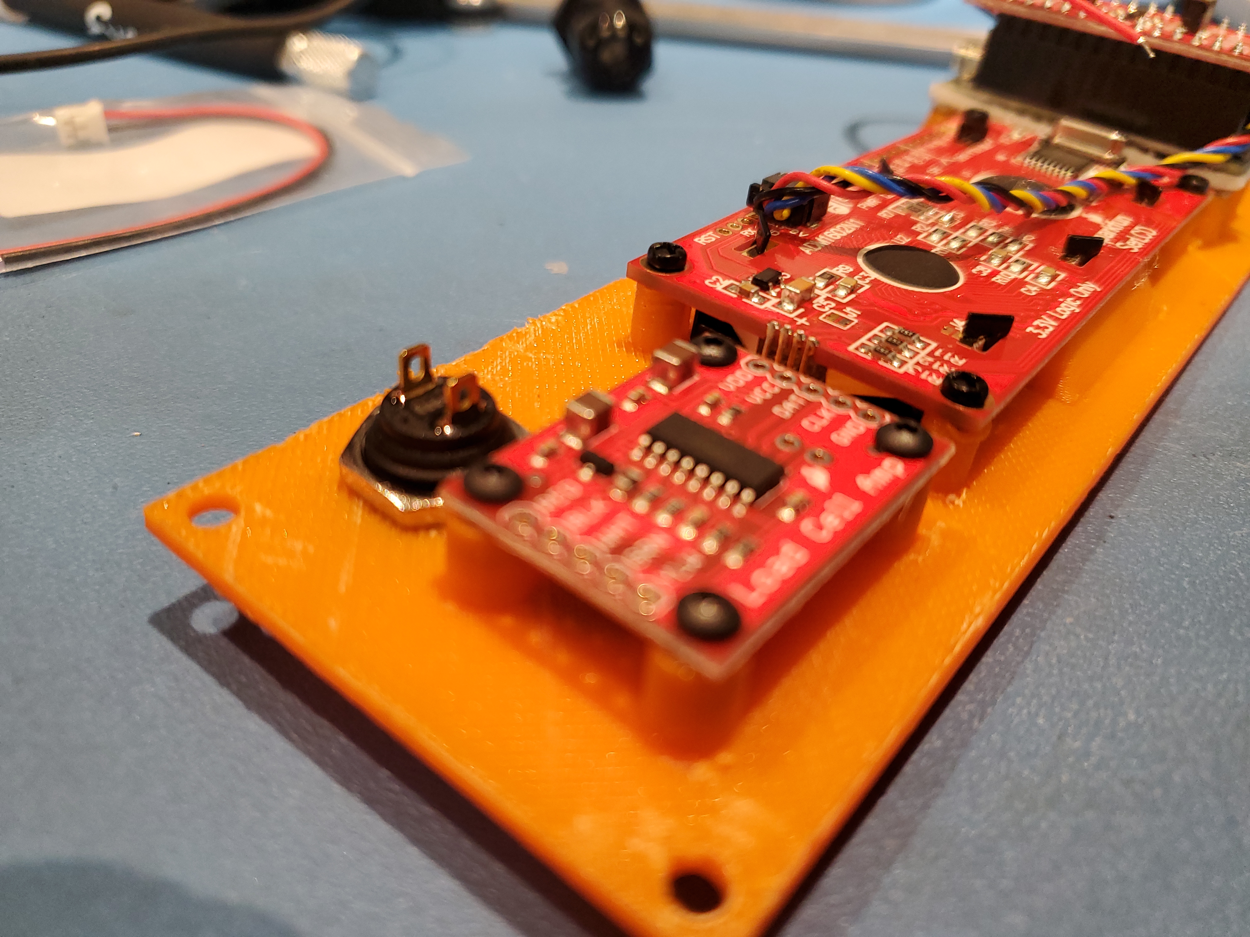
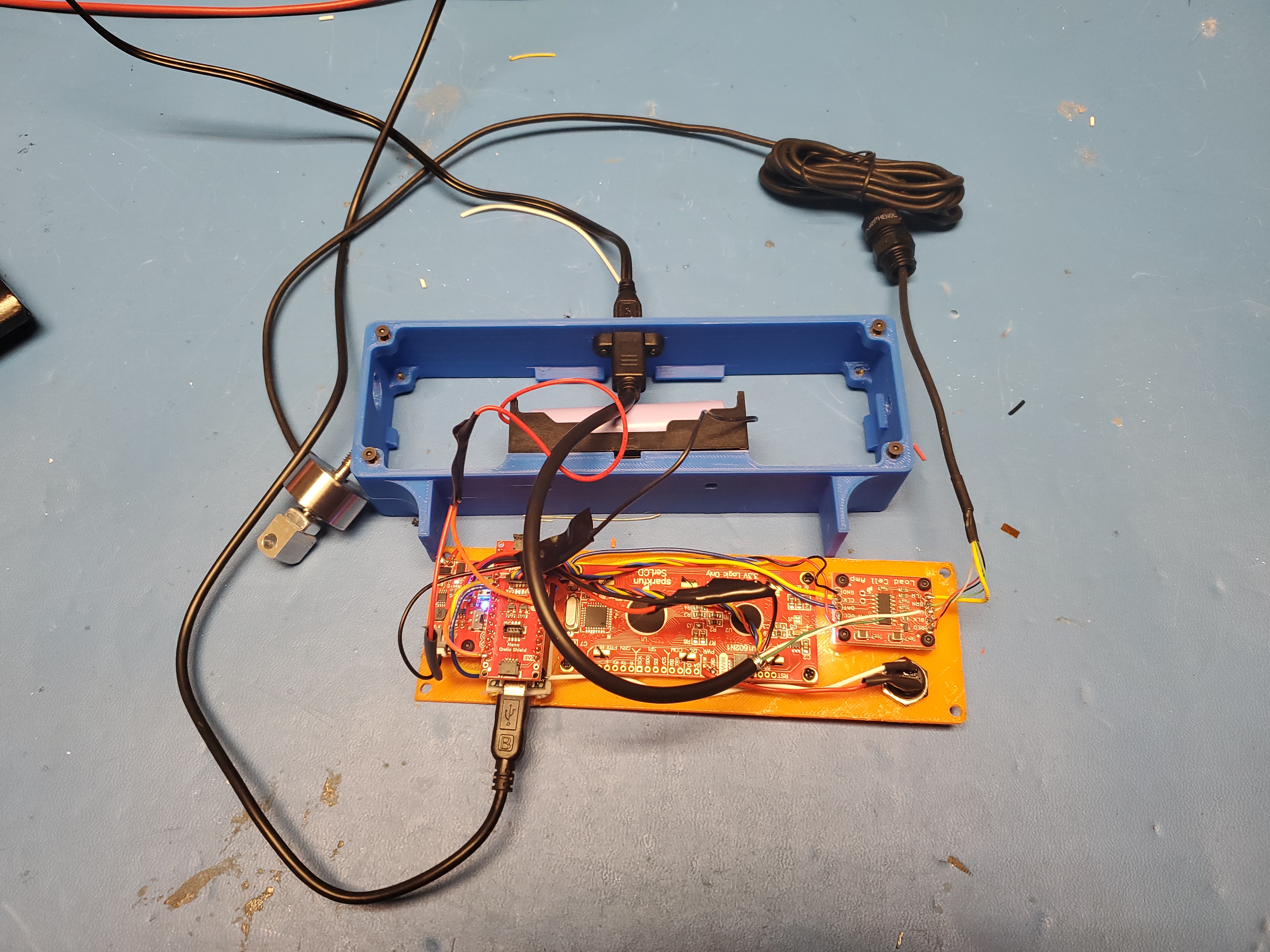
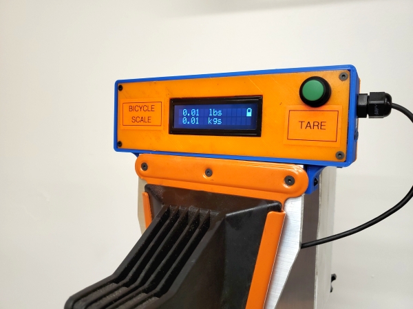
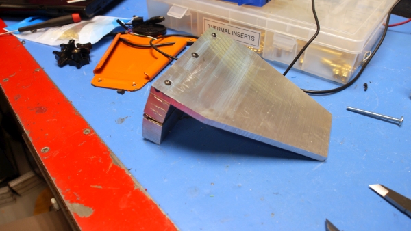
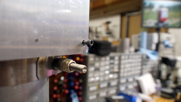
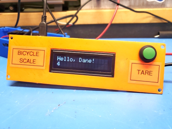
The first test setup was to verify everything worked. A qwiic connector was used to connect the character LCD to the arduino nano Qwiic shield, and a second Qwiic connector was used to provide power and ground to the load cell amplifier. I started with the hello world display example, verified functionality, then went to test the strain gauge, the 18650 voltage sense, the tare button and the external 5V bus charger input individually. Some interesting bitsInitially I had routed the raw cell voltage to pin A4 (ADC 4) however that pin is also I2C, so after some head scratching I moved it to A3. D13 was also used for the 'tare' push button sense, however D13 (on the arduino nano) has an led and resistor pulling it to ground. It still works well as an output however, the pull-up input is unreliable due to the external load. I changed the push button from pulling to ground to pulling to the 5V rail and that issue was resolved. With known working wiring, I cleaned things up, shortened the un-necessairlly long strain gauge cable and mounted everything in the case. After tying up the wiring, here's the scale module with the back removed displaying a modified hello-world display test. A keen eye may notice that the charge connector was re-located from the top to the side next to the strain gauge input. There was a bit of a mechanical short clearance for the panel mount micro-usb cable. A quick re-print located it next to the cable gland connecting to the strain gauge. This is overall a better spot as it limits dust intrusion into the charging connector. Oddly there were a lot of printing artifacts on the gap between the cable gland and the micro USB charging spot, and I opted to backfill voids with CA glue. In the shot below the KG value is just an integrator, its not actually measuring anything. I was pretty happy with how it came out, the tare pushbutton has enough support from the case such that the front panel does not move when pressed. One of the funny 'parts you forget about' is actually back light leakage. The RGB backlight for the character LCD module actually leaks a lot of light out from one side. I fixed this with a piece of black electrical tape, but made a note in the future to keep track of that. The flathead M2 screws fit well with the aesthetic of the front cover. I'd probably prefer a stubbier toggle on-off switch but it works fine. Completing the Mechanical AssemblyI needed 1 inch thick aluminum blocks at least 0.75" in width. I didn't want to special order rod stock and luckily found a really oddly shaped 1" thick piece of 6061 aluminum in the scrap bin. Time to put the *newly repaired* bandsaw through its paces. cutting 1" thick aluminum can be a bit of a chore, but I'm glad i had enough scrap parts on hand to squeeze these parts out of. Dykem Blue is finally back in stock, so I coated the top surface and scribed in a 0.75" line from the edge, down the length of the part. I needed two 5" long parts but cutting from a single long strip would be easier than cutting separately. Shown below I measured out and scribed the 5" sections. I think the base piece was some leftover from the N52 waterjet or something as I could not really identify *what* it was from. Note I let the Dykem setup for a few minutes before scribing and cutting. So it turns out one of the bandsaw guides (the under table rear blade guide) had failed mid cut, see if you can spot where. This is why later in the clip the blade looked extra springy. I was more impressed it got through all the material, I didn't investigate until after finishing the cuts but yeah *adds another project to the list*. I did actually have a table guide (the thing that runs in the groove on the bandsaw table), but given how oddly shaped this part was it didn't end up fitting. With the blade guide as close to the work-piece as possible I was really happy that the bandsaw was making it through this fairly thick material. With the bottom guide misbehaving I opted to clean the surface a bit with a recently purchased fly cutter. This was completely unnecessary but I love fly-cutter finish so, time to make some chips. The feeds and speeds here are very manual, as in I was just turning the knob on the Linux CNC pendant, still came out amazing. I cleaned up the bandsaw surface and the initial stock surface, which should make mounting the hinge a bit more predictable. Mating the two blocks to the hinge was fairly quick work, M3 is fairly small so 'power tapping' with a drill would be a terrible idea. The spacing for the holes was defined by the piano hinge itself, with spacing roughly every 2 inches. I transfer punched these. The alignment of the hinge was also straightforward as the base of the hinge lined up with the recently flycut edge of the spacer block. Otherwise this was a quick tap-drill to 0.75" depth and then hand tap operation. Note that as I didn't want to re-cut new spacers I was fairly slow on the tapping, backing out periodically for chip clearing. Its always nice when things come together, I used 12mm flat-head M3 screws to connect the hinge to the standoffs. After putting this together I opted to chamfer the hinge screw holes slightly to allow the flat-heads to recess a bit better. These are relatively small stainless flat heads, which means the hex engagement for the driver is limited and easy to gunge up. I may opt for some non stainless hardware later on. At the moment nothing is loctite-ed together. I followed the same process for the front plate mount; drill and tap M3's, thread in button head screws. These were placeholders to match up with the orange mounting plate. One of the other benefits to fly-cutting he aluminum standoffs was to help provide a flat surface for the plate to attach to. A band sawed surface would have probably resulted in some of these screws taking more of the load than others, not terrible but not great. With the 1" blocks cut, hinge drilled tapped and screwed together and mounting plate all tied up it was looking pretty good. Even though the 'barstock' was band-sawed out of scraps it looked fairly reasonable. The hinge clearance is great, the flat-head screws don't bump into each other in a parallel configuration. I opted for M3's when assembling this, which is on the smaller side but unlikely to cause issues. The main motivator for that is the orange mounting plate fits flat-head M3's fairly well but I'd need to open up the holes to fit M4's. Lets get on with tying up the mechanicals. The strain gauge needs to be constrained but not over constrained, so it mates to the plates with a pivot mount on either side. This is technically a 'printable part' as the actual loads are not incredible, but its also really quick to fabricate out of aluminum stock. We know that the strain gauge threads are M6, and we know that the spacing for 'parallel' on the bike holder side will require some adjustment, so a thin box nut can be used for keeping the strain gauge from moving and adjusting the horizontal offset. I opted to make this from some scrap aluminum plate stock and again it was a fairly quick, drill-tap and cleanup. The only real constraint was ensuring that the two drilled holes were perpendicular, but that was achieved by using parallels in a vice. To attach between the strain gauge pivots and the plate I opted to use some simple angle aluminum. The only part that needs to be somewhat precise is the location of the holes that act as the pivot, as they need to be perpendicular to the strain gauge. This is easy to do by just drilling both at the same time in a vice. To attach to the base plate and the pivot plate, I punched and drilled out for M2.5 screws. The location of the screw holes were transfer punched into both plates and they were in turn tapped to accept the small brackets. I started with attaching the pivot side first, then double checking alignment before attaching the base plate side. The two 25mm M5 screws used as the pivot mounts could have been shoulder bolts or pins but they appear to work well. The screws are purposely loose, and the nut is held in place with Loctite adhesive, They are just there to prevent the screw from sliding out, these could be aluminum rod-stock, tapped at the ends for constraint bolts. 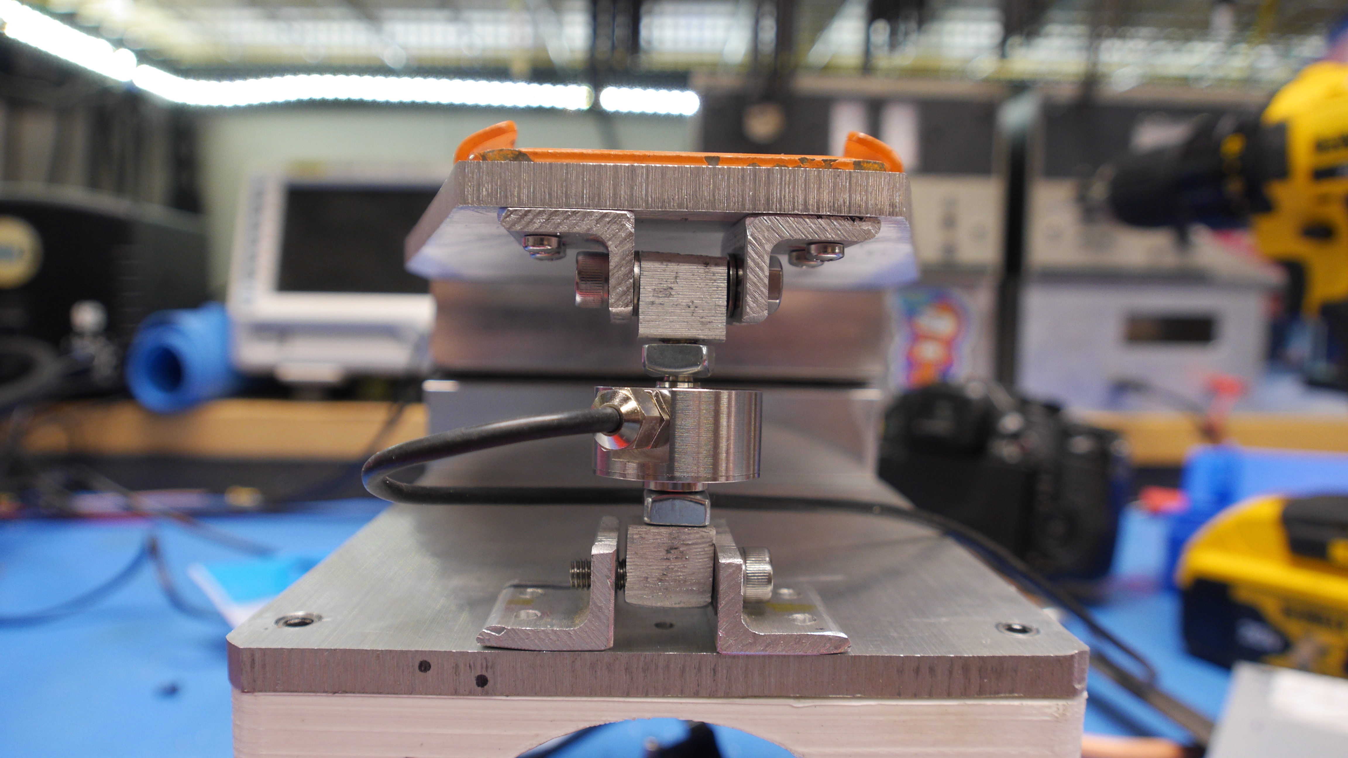
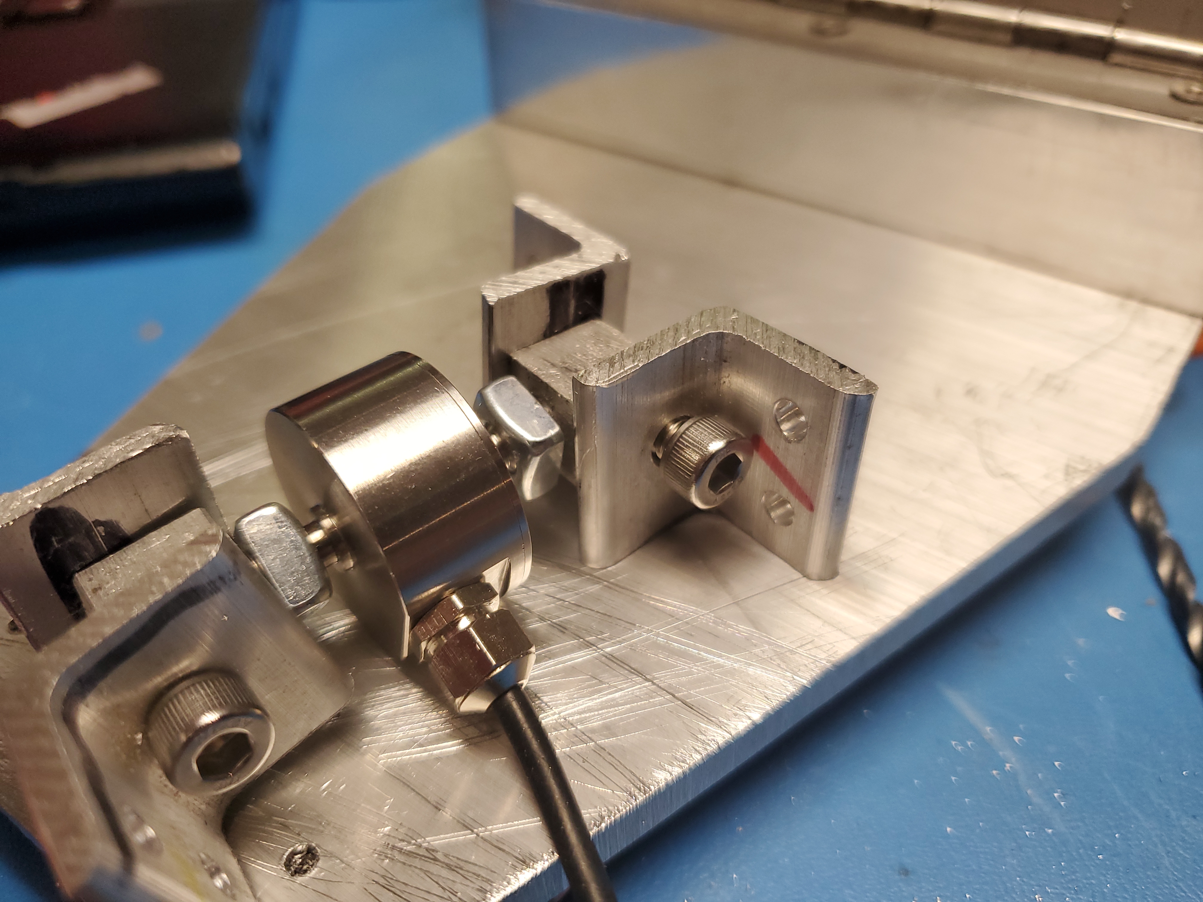
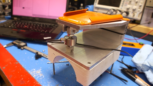
With the strain gauge mounted, roughly perpendicular its time to tie up the electronics and mechanicals. After shortening up the ~3ft of strain gauge cable and re-terminating internally its time to connect everything up. Its always nice when something 'just fits' while 3d printed parts can be dimensionally accurate, they can also not be. I drilled and tapped two M3 holes into the front-facing standoff so that it cleared the removable bike mount. The only protruding parts are the cable between the scale and the strain gauge. Ive been on the fence regarding adding an in-line connector, at themoment they are tied together. Otherwise that's it, the 18650 battery is internal, and it can be charged via a panel-mount micro-USB connector. I may replace this with a USB C panel mount connector [link], if it can be convinced to fit in the small space available. Lets see how it works. I needed a scaling factor for the strain gauge output, and while I could reverse it out of the lever arm ratio and the somewhat dubious amazon link datasheet, we can also just check with a known mass. I measured against a 'gravity rectangle' aka a painted lead brick with a handle on it. The lead brick is 19lbs and that resulted in a calibration factor of 3.86:1 which is roughly what the drawing came up with. Its working! There's plenty to do on the software end but they are all relatively quick. First pass, it just works! Its firmware timeI have a few parallel things that need to be implemented, its easier to put together a quick draft of rough 'requirements' before running wild in firmware land.
Drawing 'custom characters'
I like to break software into small parts to prove out implementations before gluing them together. This one's curious, start with a variable representing the 18650 cell voltage [0000mv to 4200mv] and represent it as a custom character, then take in the GPIO from the external 5V charge connector and display that as a separate custom character. To do this we need to write custom characters to the display directly. Writing to a normal character LCD to make a 'custom character' is actually not bad. Here's three of the custom characters, sketched visibly on graph paper, and how they get implemented in code as a byte array. Note that the byte array is literally the pixel map for the character. There's a great writeup on this here [link] 
And it works! In this case the GPIO input for the charger gets checked every 250ms and updates the indicator status when it changes. If you're interested on implementing something similar (a bar graph or some other custom characters) I made a basic arduino sketch and included it on the GitHub repository for this project [link], specifically "example_battery_custom_icon". Example code for custom characters: [example_battery_custom_icon.ino] Example code for reading scale, hardware pushbutton for tare, etc: [example_read_scale.ino] Implementing Scale averaging and Tare ButtonThe HX711 library has some convenient documentation here [arduino library github] which is incredibly convient. The scale implementation mostly used primitives from this library without many modifications. I did notice for 'tare' it was important to wait until the user was not touching the stand, as leaning on the pushbutton did effect the reading, so the easyiest way to do this was to have a delay loop and onscreen instructions to have the user step back, then perform the tare function. Source CodeGitHub Repo [link] Raw copy of the latest is available below if GitHub is down: [bike_scale_display.ino] Tying everything togetherIts quick and it works, the bike is constrained and well above the ground without any real worry of it toppling over. 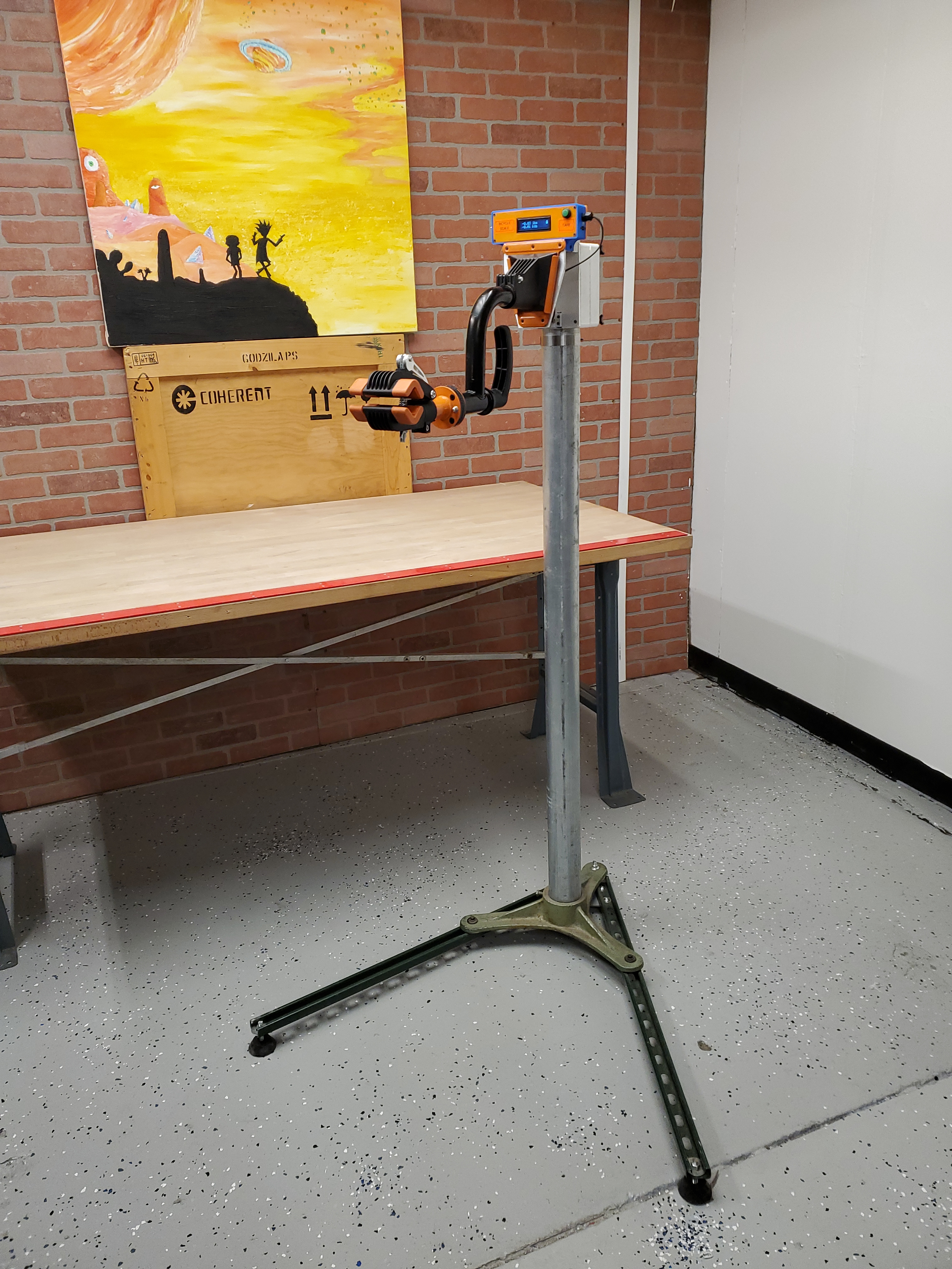
While this is a simple/quick project its nice when a project becomes a tool. Speaking of, whats the battery life? Good question. The mystery 2.2ah surplus 18650 results in about 2 days of constant use (21 hrs) before the undervoltage cutoff kicks in. Thats with the display brightness on full and no power-saving modes implemented. Speaking of, that might be a good idea on a future firmware version, crank down display brightness if the value has not changed by x% in x minutes, that should really extend the runtime. Design Files
Concluding Remarks
Have you noticed that there are no advertisements or ridiculous pop ups?
|
Bike Arm Mount
The Stand
Adding a Scale
Scale Electronics
BOM
Scale Mechanicals
Assembly
Firmware
Custom Characters
Averaging
Source Code
Final Product
Design Files
Concluding Remarks
Post your comments! |
|
Comment Box loading
|