
Dane Kouttron
Project Started: 12/2018, Re-Formatted 12/2023

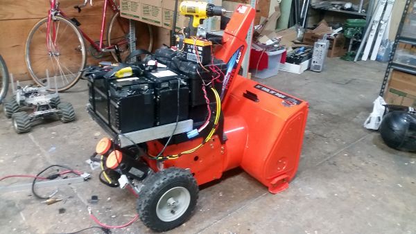
Snow, robots and obstacle avoidanceIn late summer, I was gifted a really curious contraption: a non-functional, electric powered 2-stage impeller snowblower, in late summer. It was headed for the trash, but some excellent folk couldn't see it get crushed, and found me. The electronics and batteries were shot, but the mechanicals seemed fine. Six months later, a mega storm Bomb Cyclone, provided some incentive to revive the beast, give it newfound remote controls and a vision system Follow along for brushless motor controllers, high power batteries, wheelchair motors and remote control goodness. |
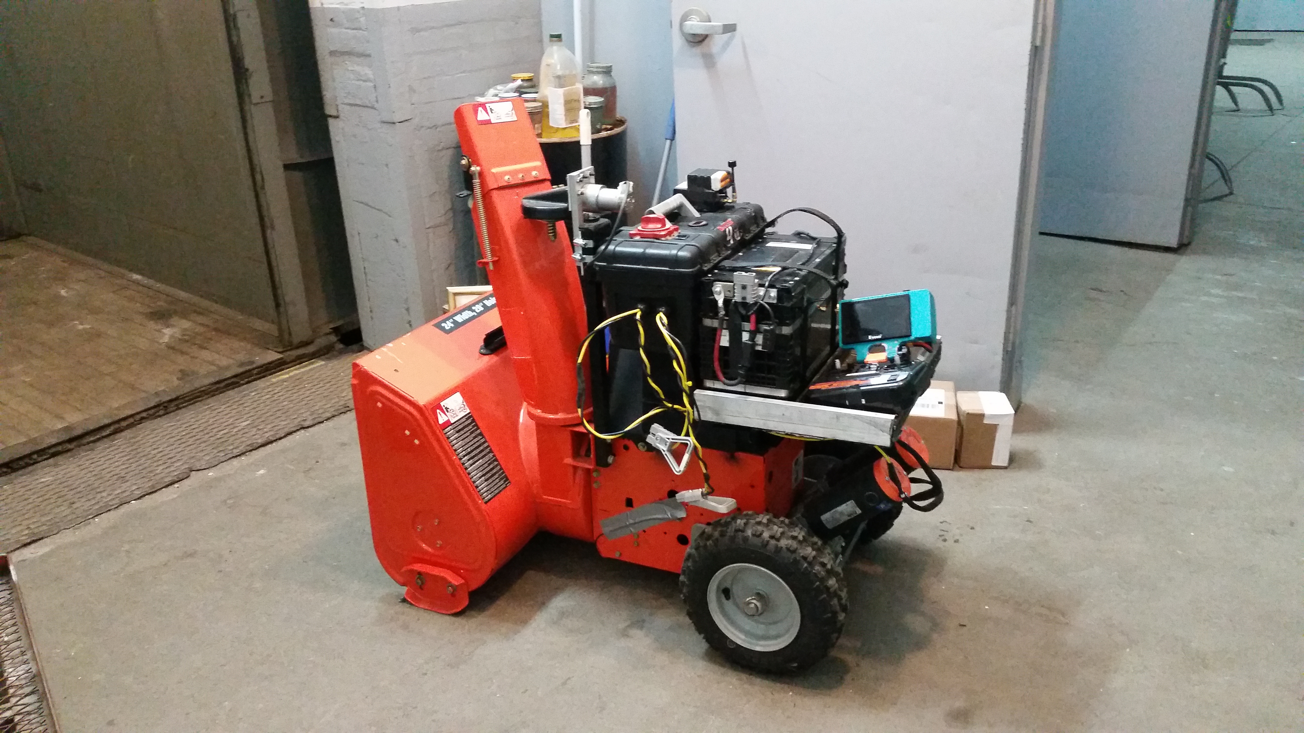
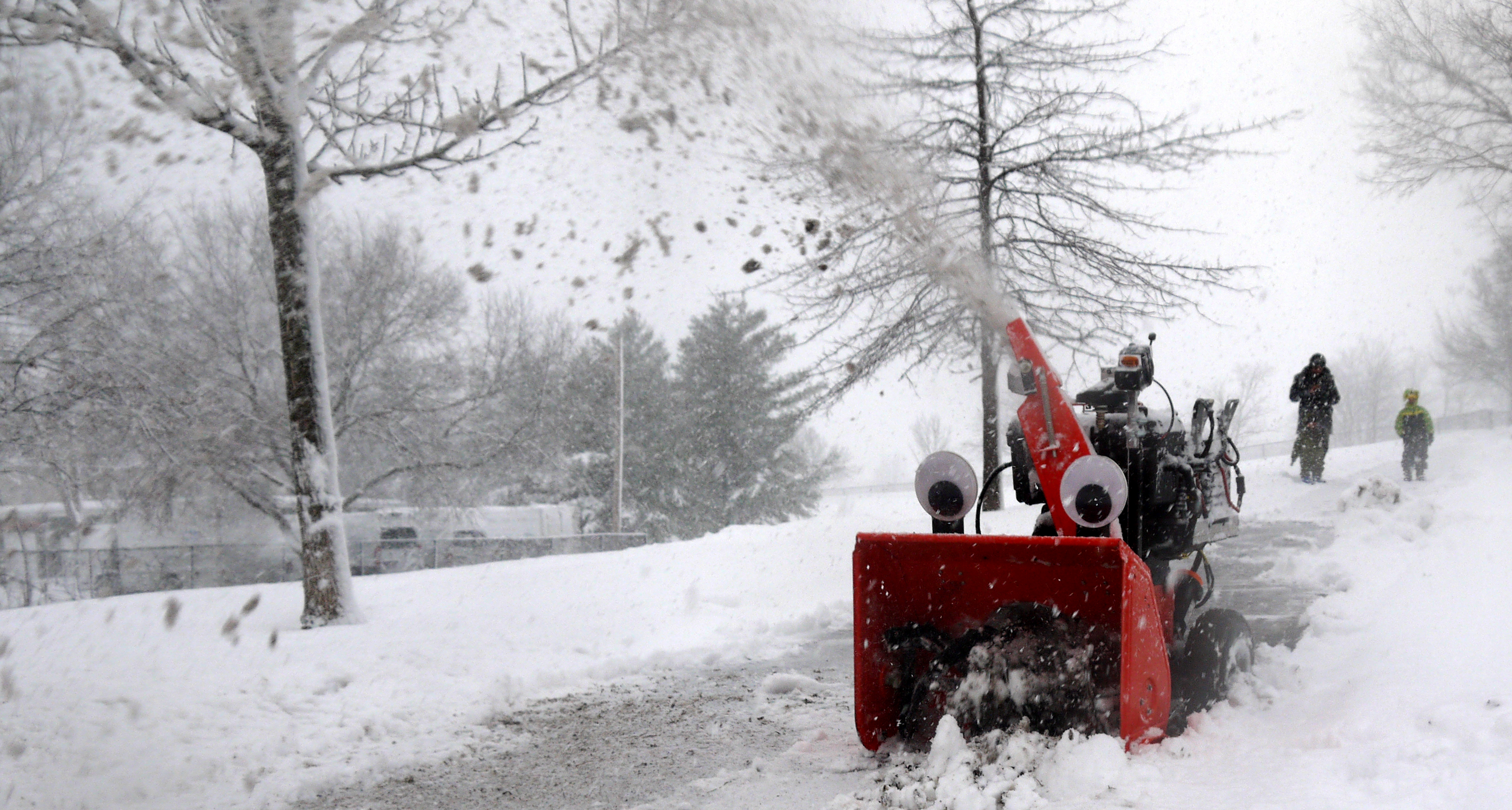
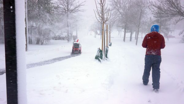
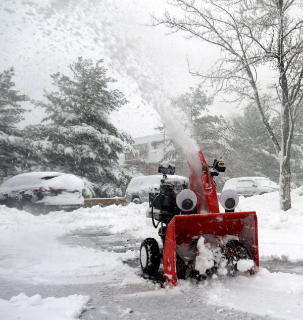
Chomper the Robot Snowblower clearing 'Dane'hy Park, Cambridge MAThere were a few quite big snowstorms on the east cost of the states during winter 2018. The first storm of the season was declared a BOMB CYCLONE to a lot of media exclamation. 'Chomper' was born the night before the blizzard as a 'I would like to sit inside and have tea while a machine does work for me' solution to this problem. I had the remains of a 90's snowblower, wheelchair motors and a pile of 2016' era battlebots parts handy. Shown is 'Chomper' clearing a local park (testing area while I worked out operational bugs). For build details, testing and sciencing, tune in below. Testing in early 2019 on the Nashua River Rail trail. Quite a bit more ice under the snow than anticipated, but alas the IMU was able to keep up and maintain a roughly constant heading. BackgroundA STORM APPROACHESShown below was the radar plot. The mega-snow-storm was projected to appear at roughly 4 AM. Boston/Cambridge went from silent to hammered with white fluffy precipitation in a 3 hr period. In anticipation of the storm, MIT was closed. During the storm the commuter train lines immediately fell apart / ran 3 hrs late. Proper Massachusetts. I took advantage of the downtime to stay up late and bring to life Chomper, and fight snow with robots. This was one of those scenarios where having a looming deadline was quite the motivator. 


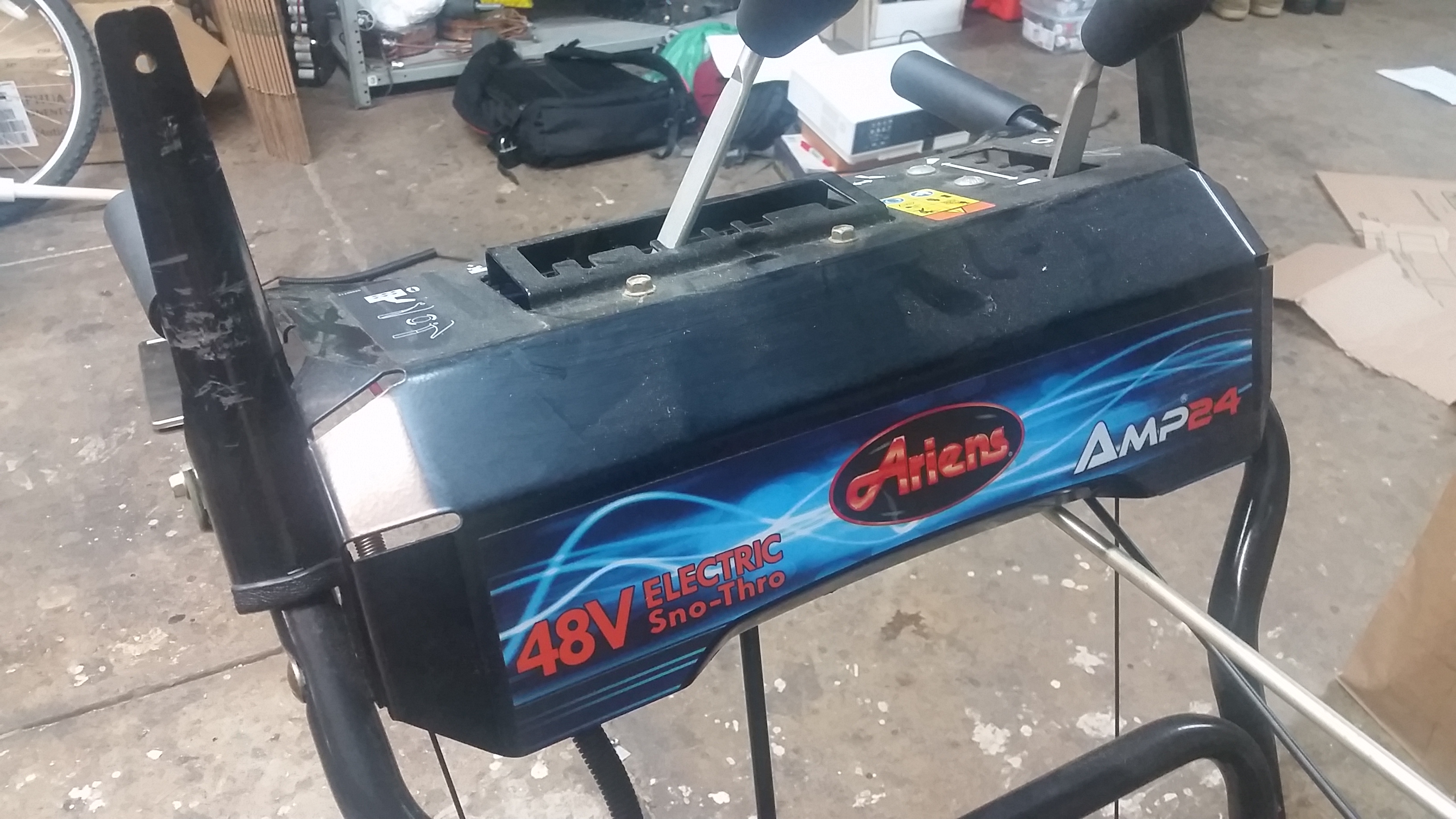
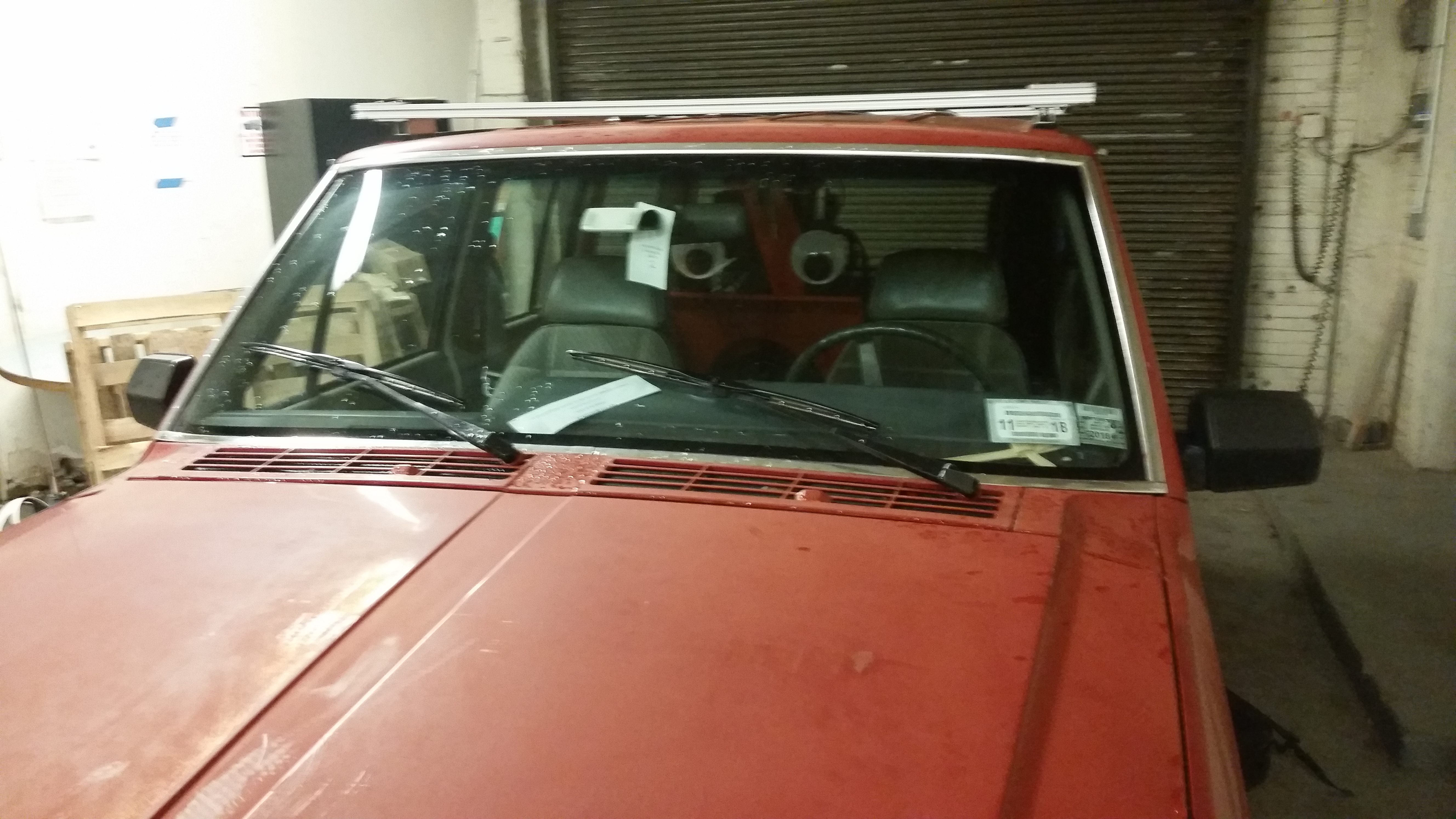
An overview of the host snowblower.The actual snowblower model is 916003 from Ariens (shown right). On the control handles it displays Ariens AMP24 48v electric snow-thro. The controls are fairly identical to a normal 24" snowblower, there's a clutch for enabling and disabling the impeller, an adjustable speed forward and reverse and a clutch-enable for forward and reverse. Here's the Ariens manual [link] and quick start guide [link], for reference. 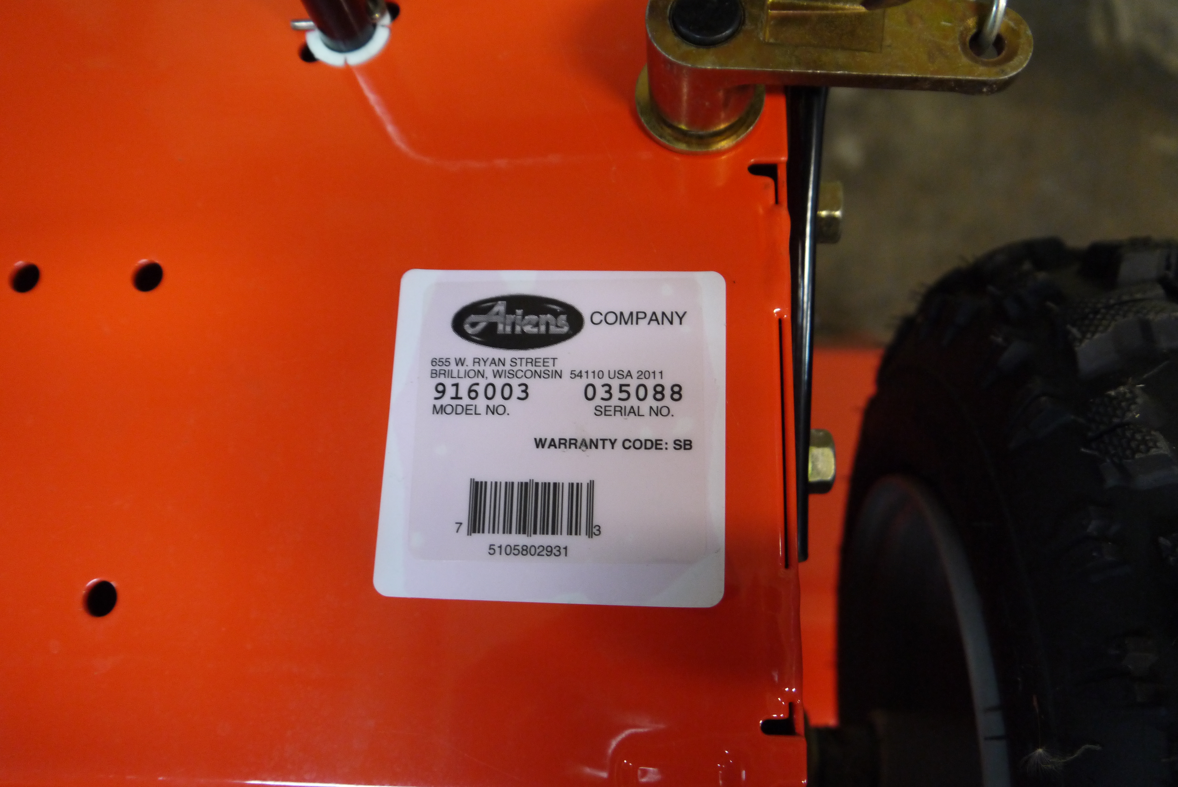
Why is there a clutch on the impeller? The electric motor doesn't need to run constantly, it can be shut off and turned on in an instant. The further I investigated the more this appeared to be a standard chassis with a big 3 phase brushless dc motor bolted in where a gasoline power plant once lived and not much changed else-wise. Given the vintage i'm honestly surprised they didn't go with a big DC Brush motor, but I cant complain about a large brushless motor! 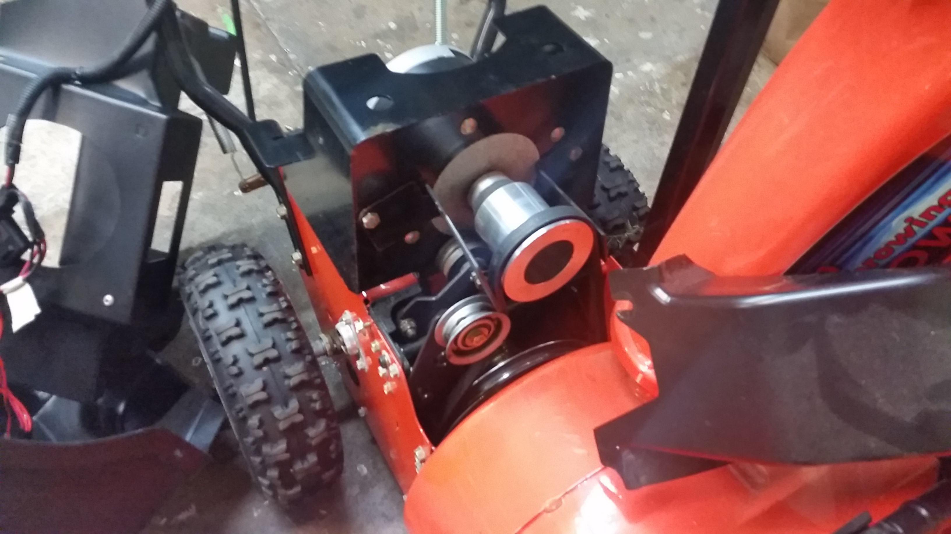
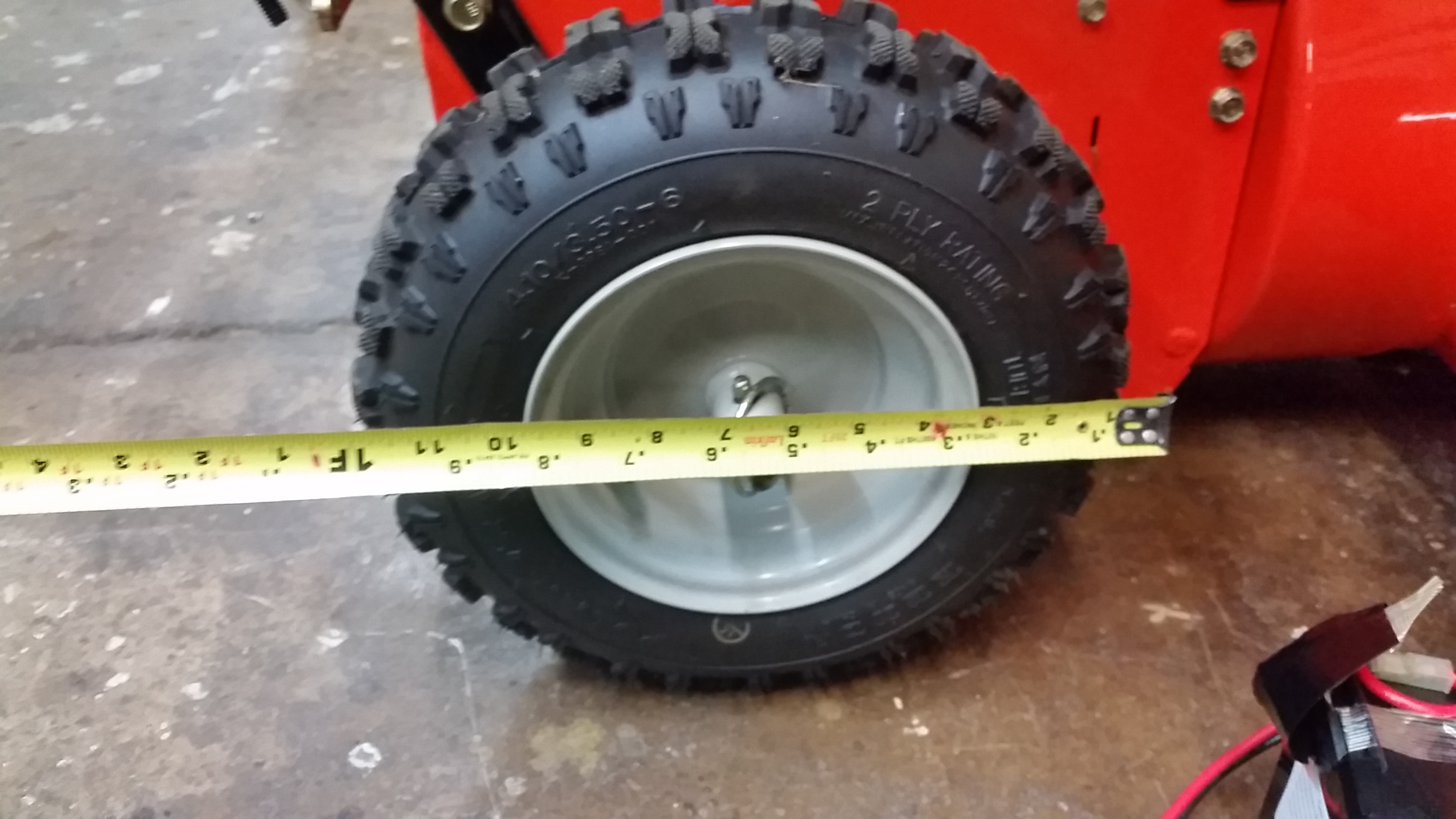
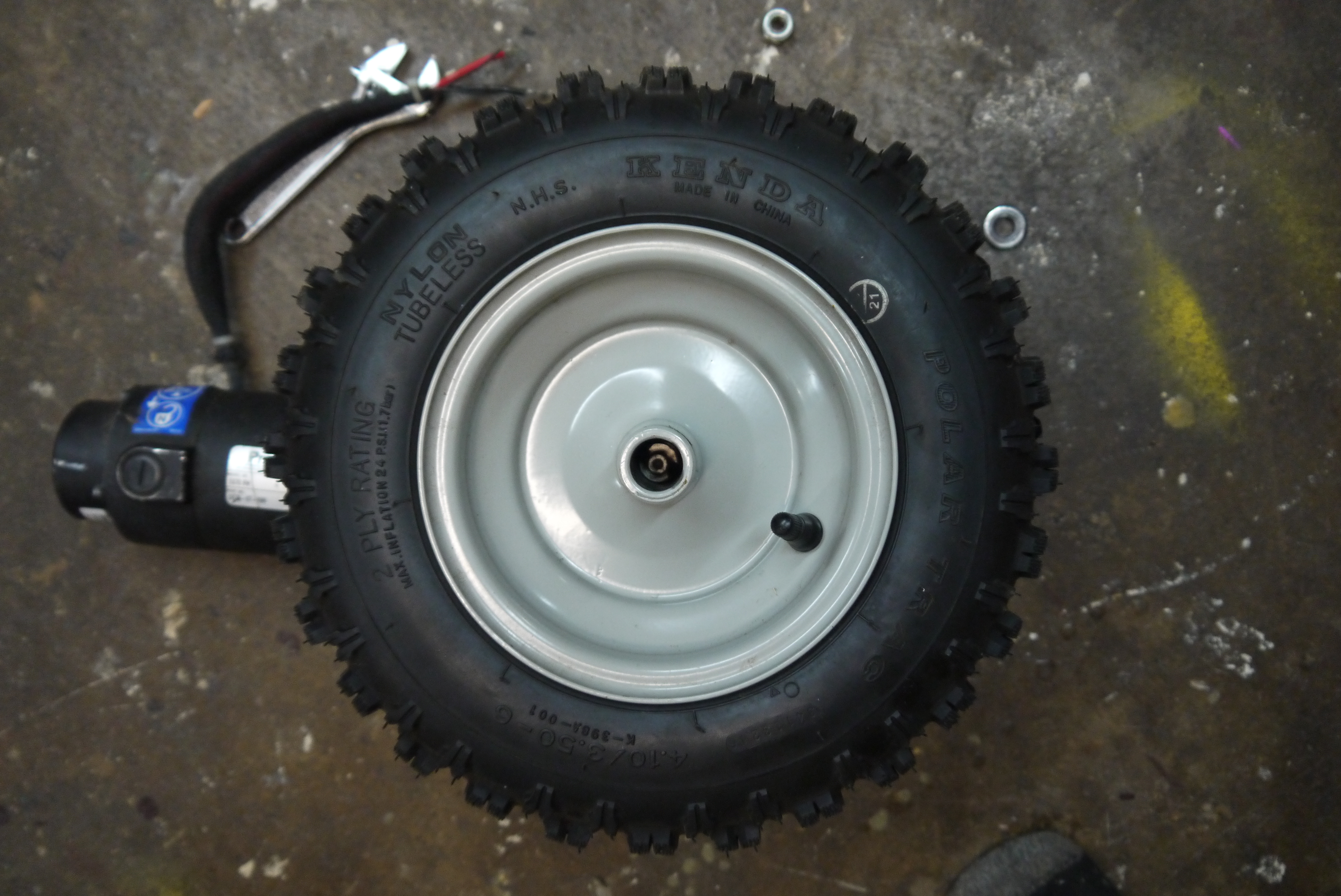
Some more quick dimensions:The tires were quite tall, coming in at approximately 12 inches in diameter. They were in surprisingly good condition, no dry rot or rim-rust was visible, quite unbelievable for something that was hiding in Massachusetts. The 'chomping height' came in at 1ft 9 inches (beware the tape measure shown right is in inches / deca-inches). 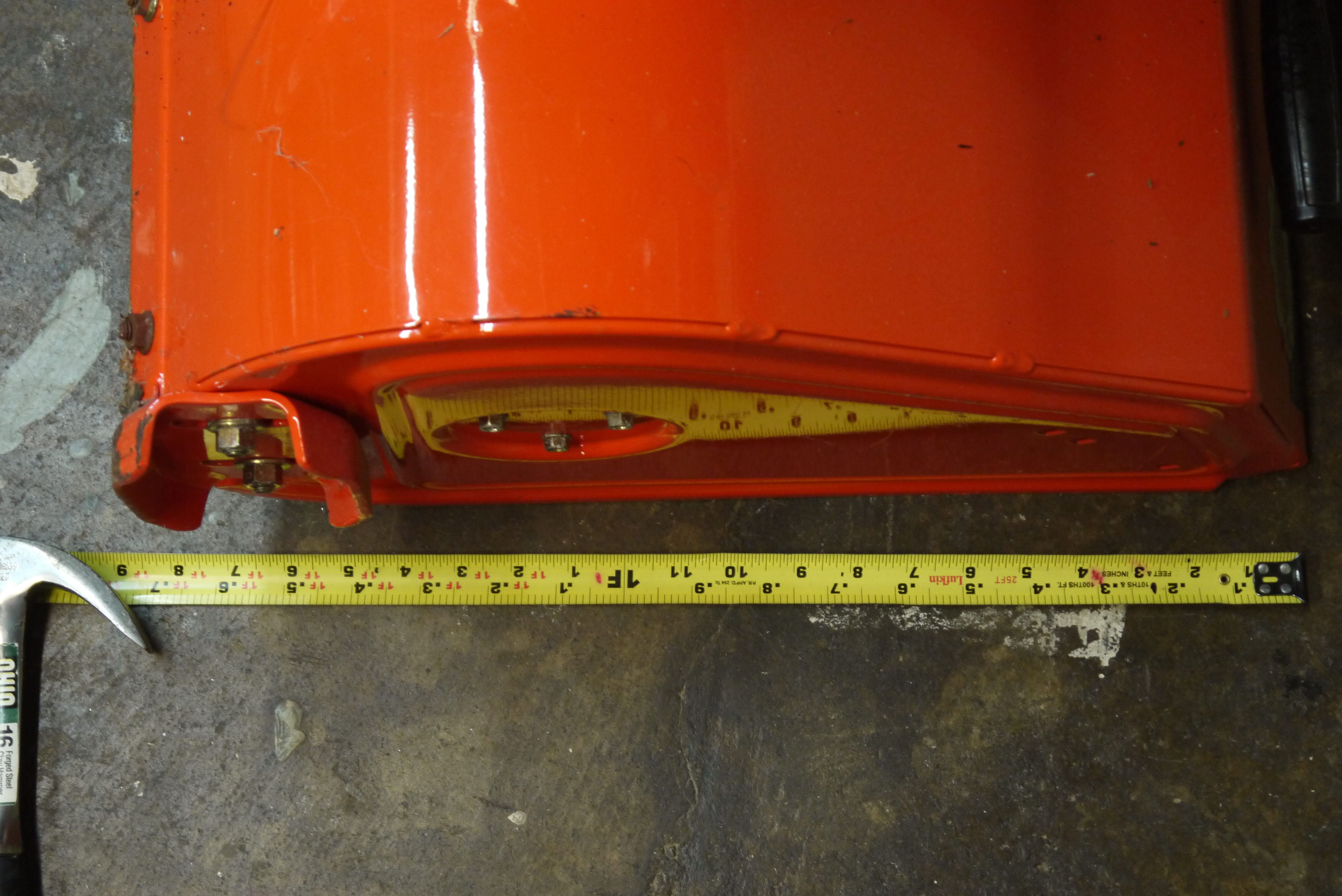
Wait what powered this thing?Four 12v 15 AH batteries were merged together in two heat-shrunk assemblies to form a '48v' 15ish AH battery module. One thing to note is '48v nominal' equates to 60V charged. More on that later. Some properly big connectors were used along with appropriate gauge wire. The modules sat on a plastic 'bench' where the conventional internal combustion engine would sit. 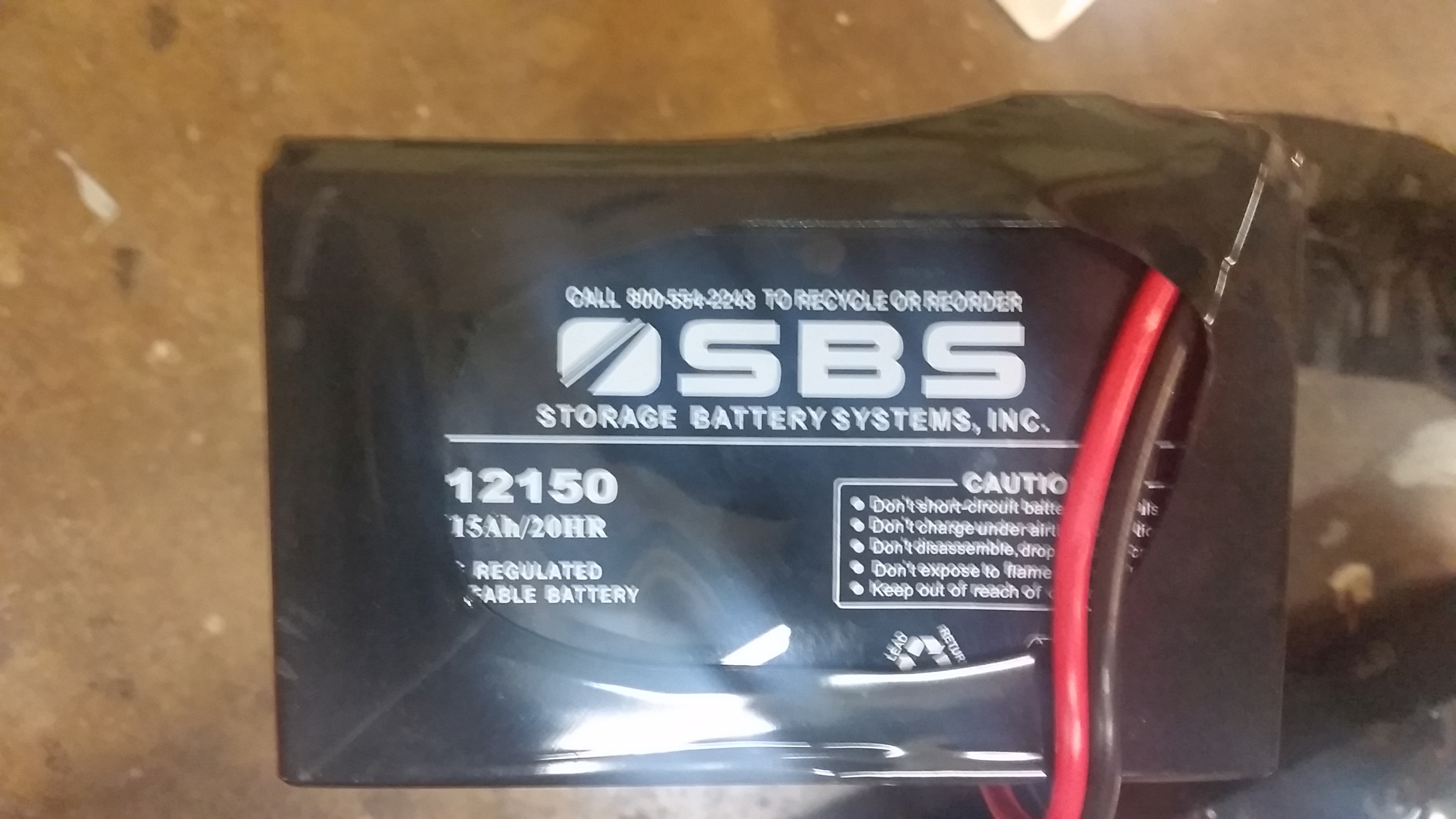
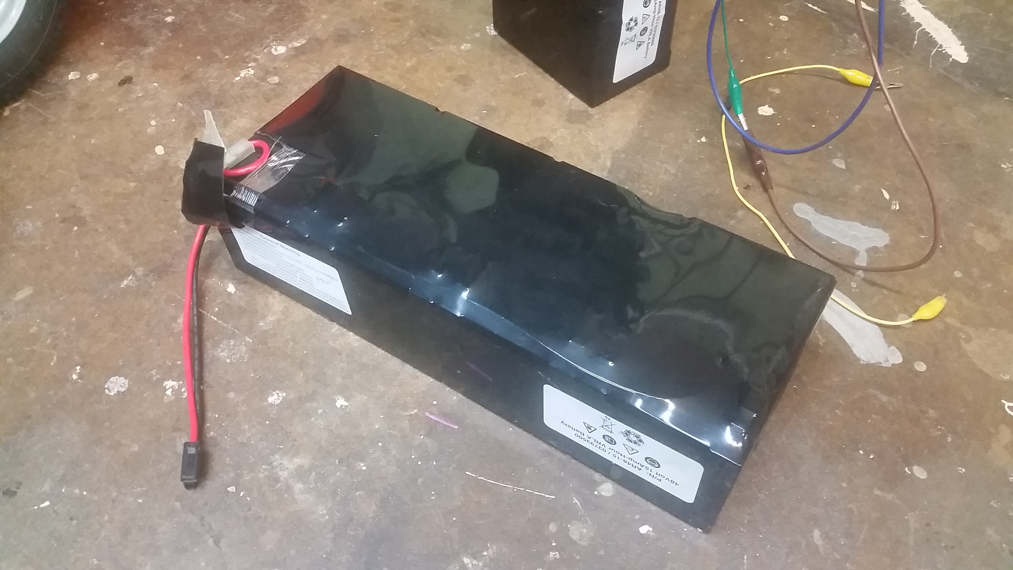
Shown with one of the battery modules removed and stacked nearby. Each 24v sub-module was quite dead showing up at ~4-6v and not accepting charge. Most likely the electrolyte had long since evaporated off. Their bulgy state could indicate an over-charge, but its not terribly clear what happened. 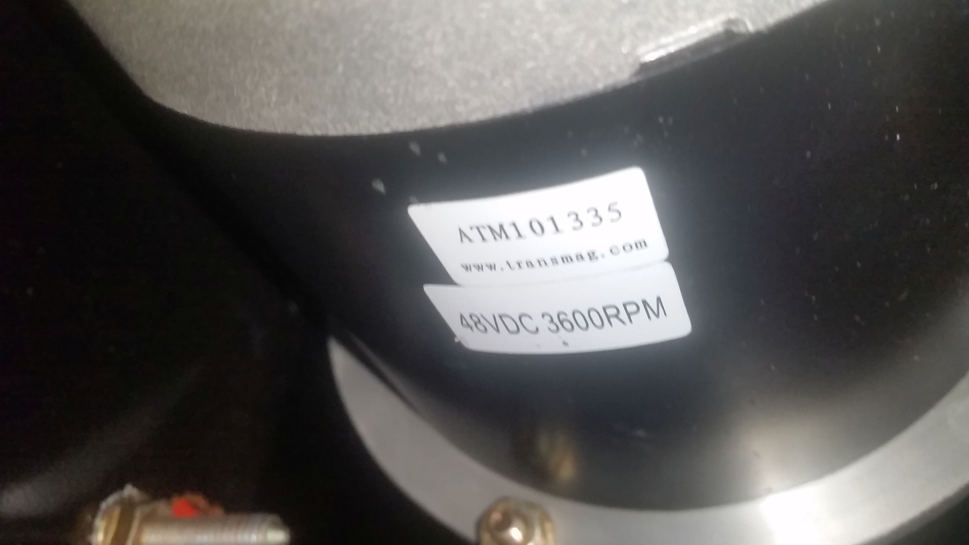
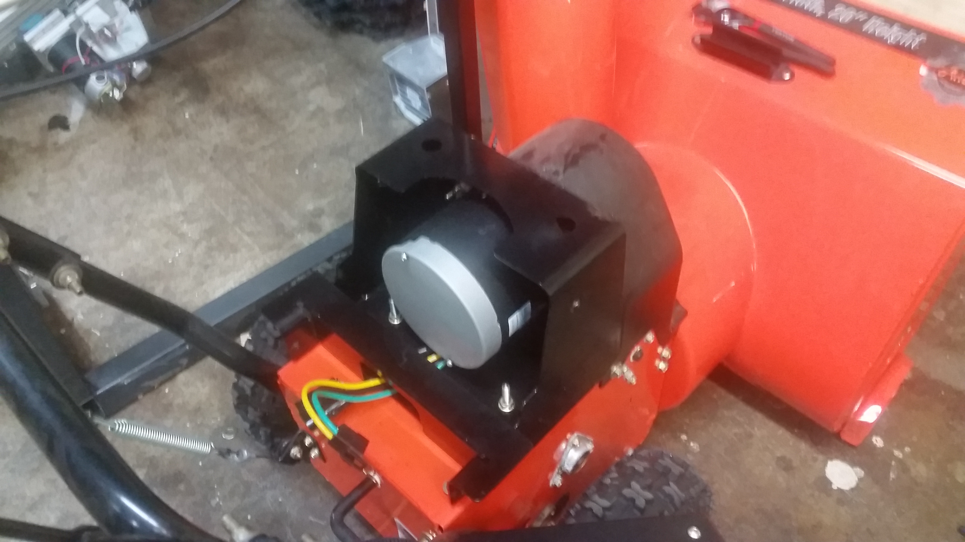
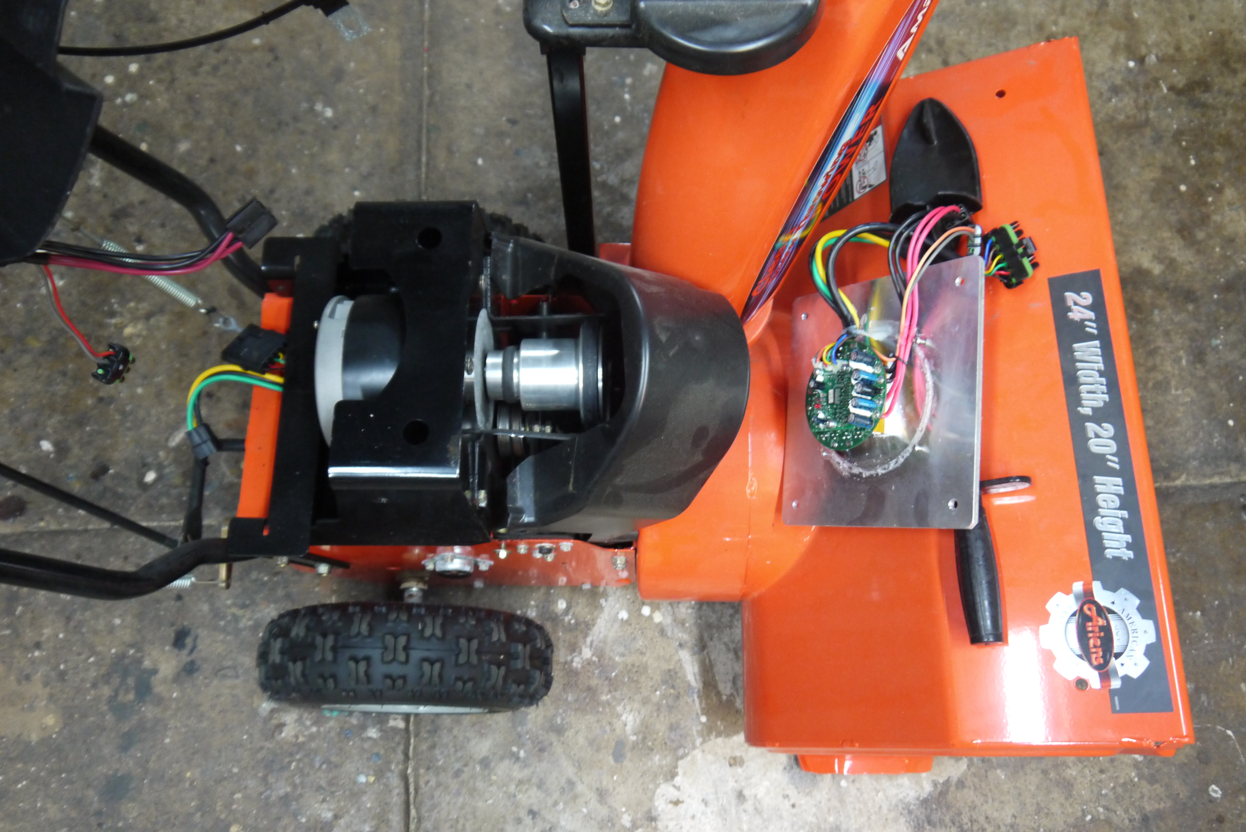
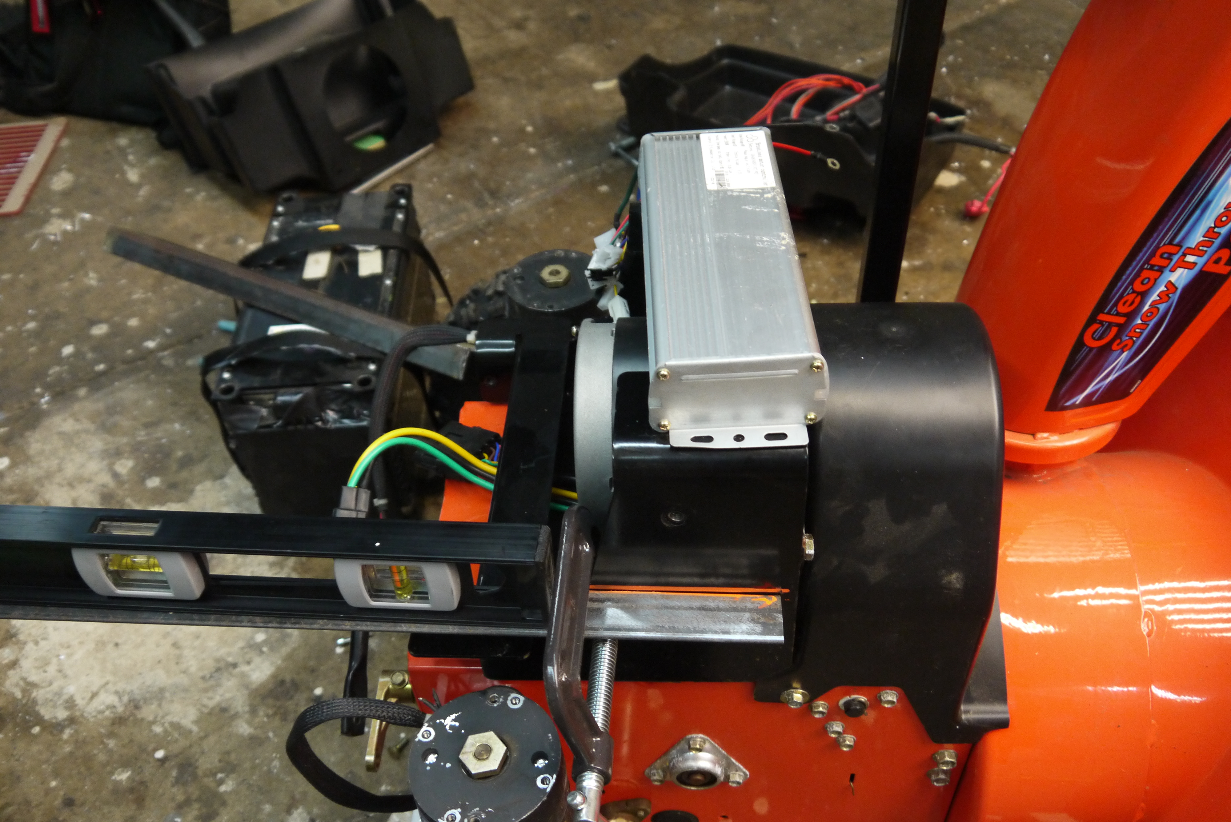
Show me some motor!The stock motor is quite excellent! I honestly expected a large DC brush 'floor-scrubber' motor and a low-side chopper based controller, but they went all-out and chose a 4kw BLDC beast. This snowblower was of the brigs Straton etek generation but they possibly chose this as it has no exposed brushes to wear / corrode. The motor part number is ATM 101335 by transmag. [link] 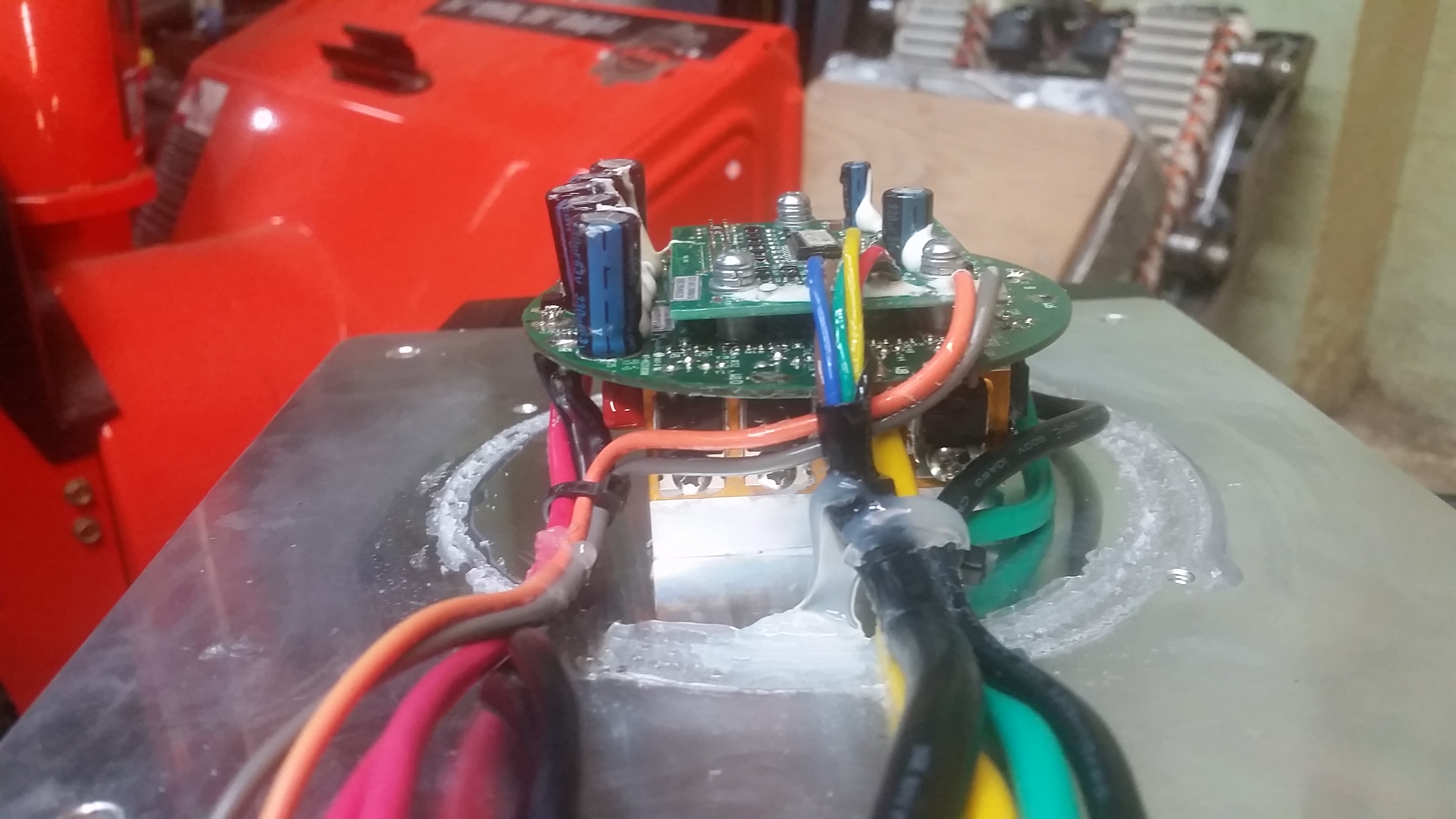
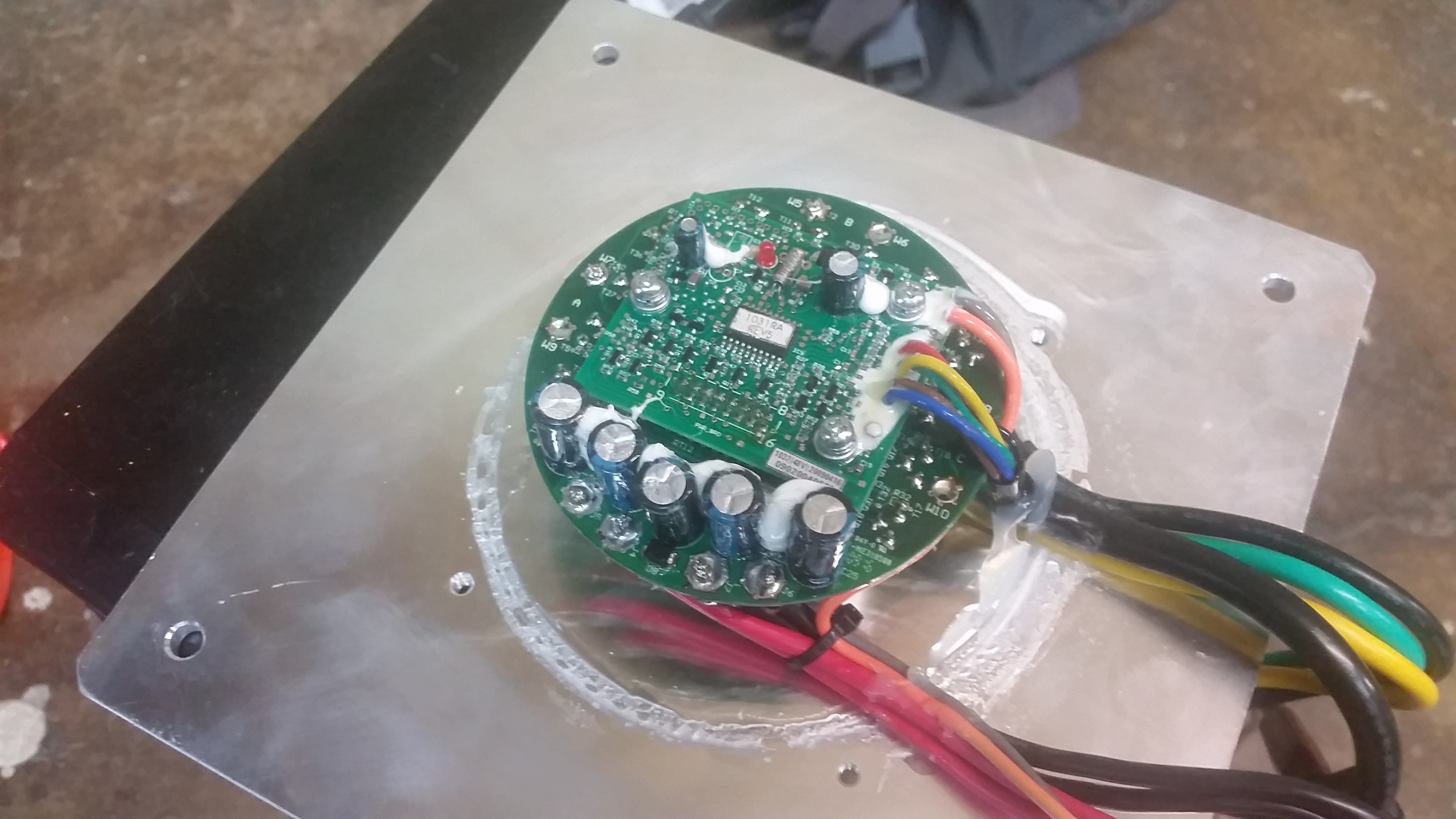
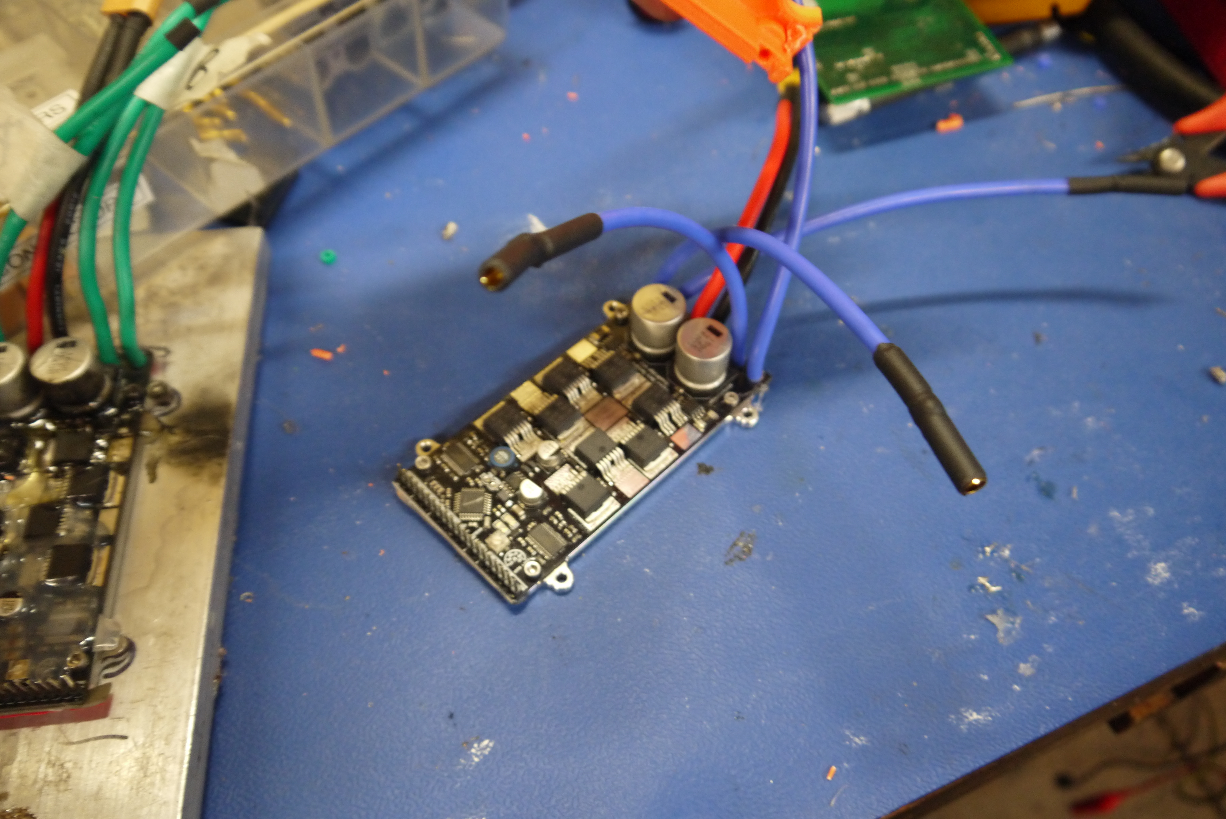
So what was driving this?The snowblower itself didn't awaken when connected to a power supply at appropriate voltage, in fact, it pulled as many amperes as it could at ~1V. Something controller related died fairly hard. The controller itself was the most bizarre layout I've seen. It consisted of a milled aluminum square with TO-220 fets screwed into it. And a tupper-ware shaped container RTV'd in place to seal it from the outside world. Quite Odd. 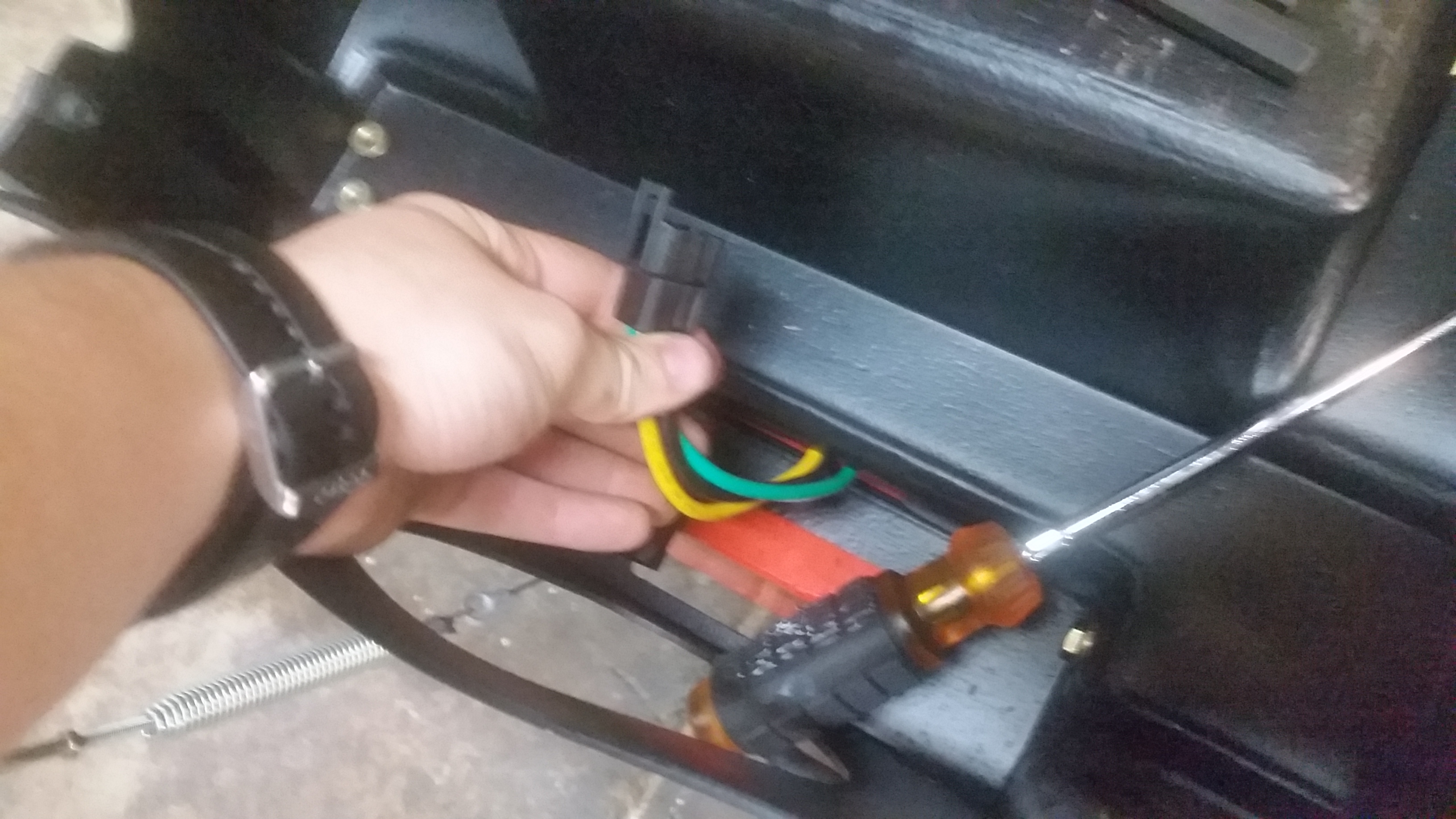
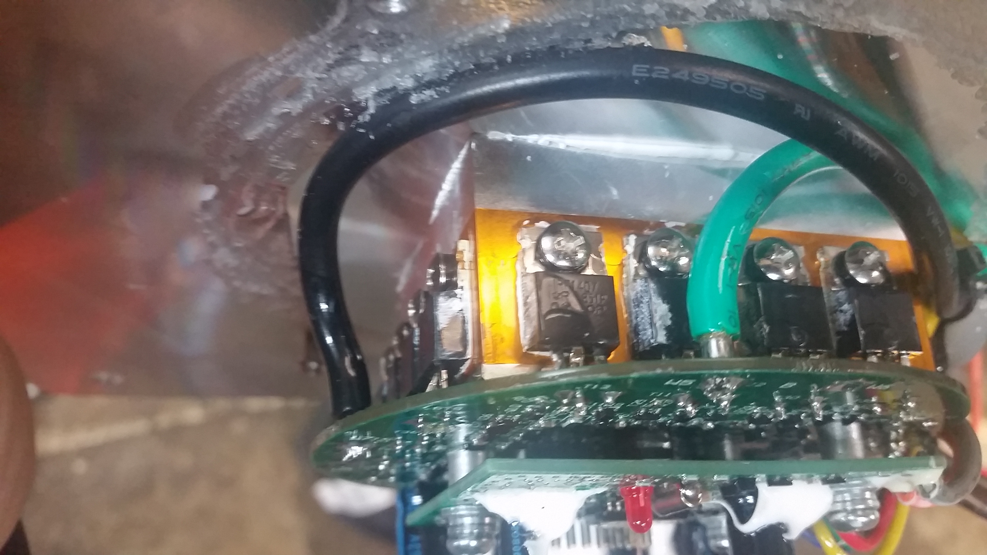
The mating plate of the controller radiated to the outside world and wires were soldered directly to the board. The controller itself appeared to be a bldc cd-rom drive motor controller with a way bigger power stage. Shown are the TO-220s electrically isolated with what appears to be kapton tape. It was quite dead, and appeared a bit underpowered for the 4kw motor so I opted for a simple off the shelf upgrade. BLDC e bike controller ahoy! Fortunately everything was connectorized with some odd, yet high current well sealed connectors. 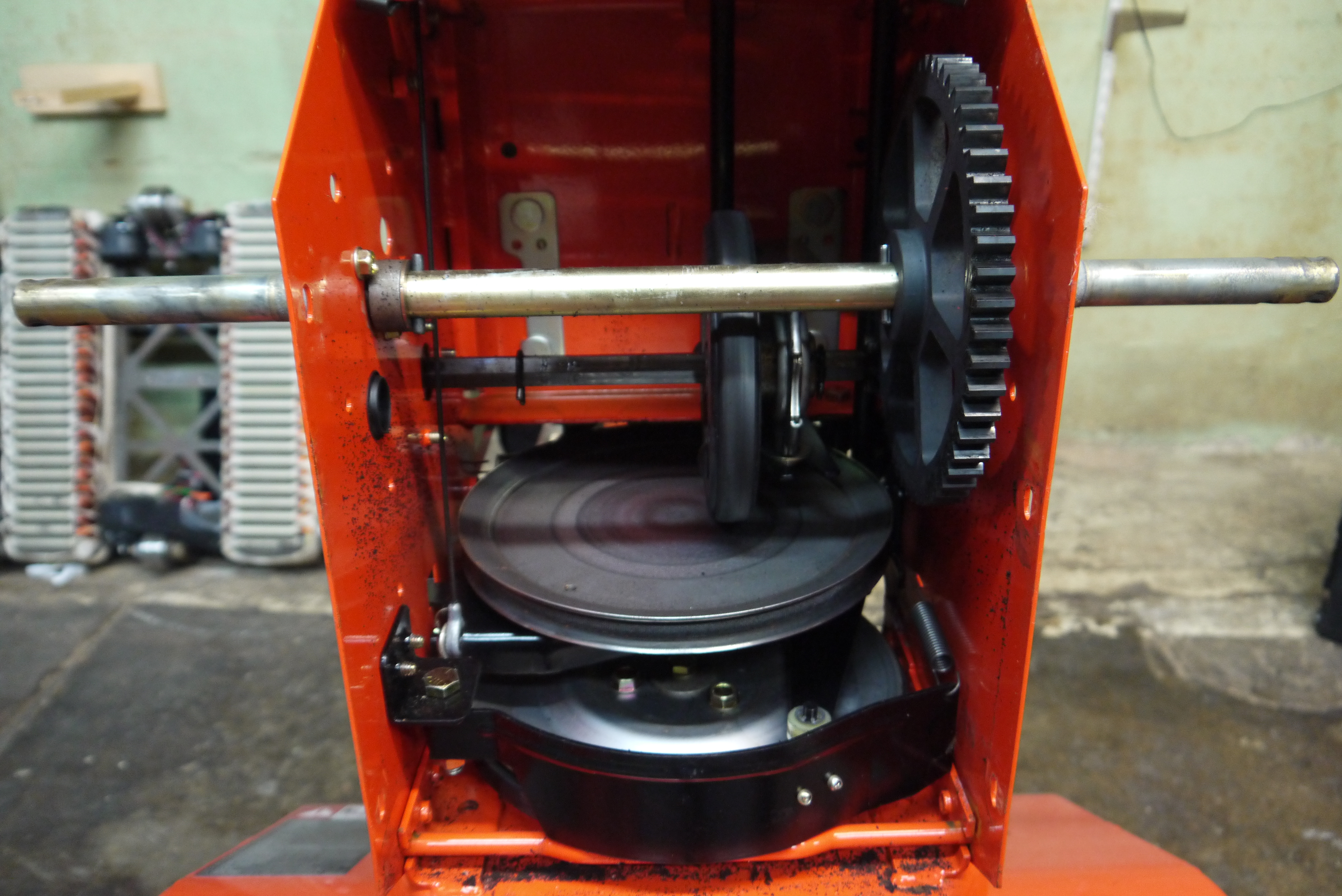
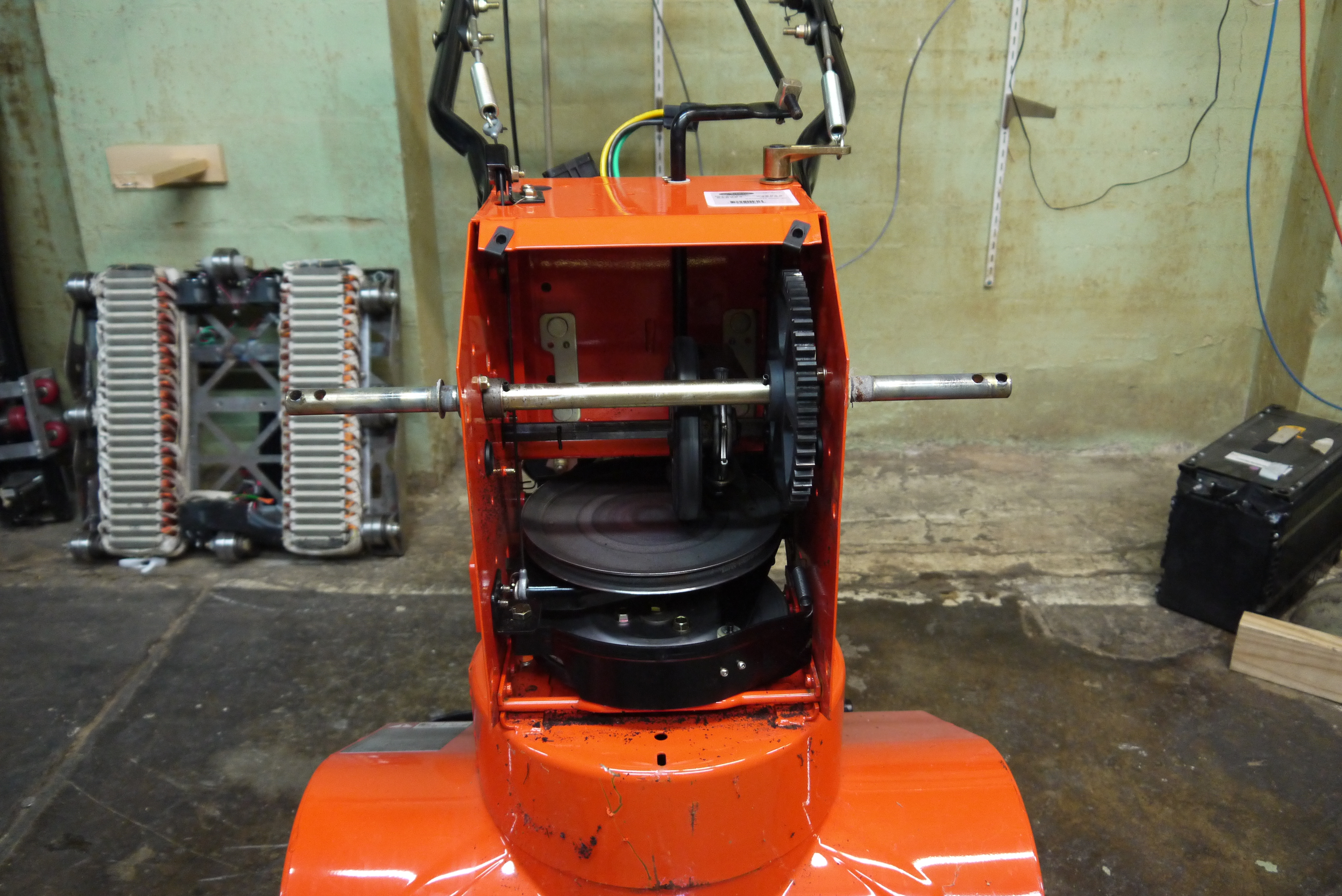
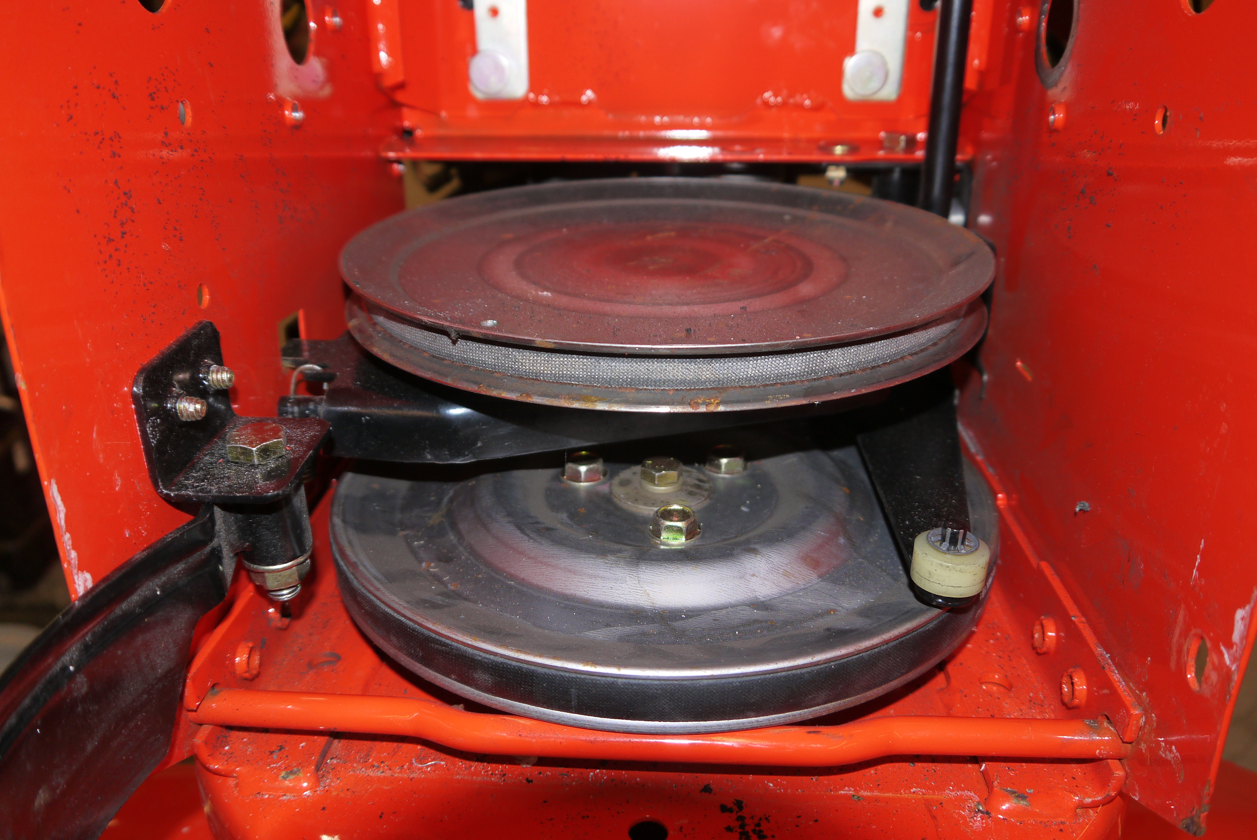
So what's going on inside the beast?Insides are surprisingly standard, there's 2 pulley-belt assemblies one which has a clutch to drive the impeller and the second which has a variable-speed friction transfer for fixed-axle drive wheel and then a 'nice-n-loud' spur-gear reduction. This is basically identical to a conventional ICE snowblower. Two bushings are housed on the inside to keep the low-rpm shaft reasonably retained. I imagine ball bearings here would just corrode too quickly. 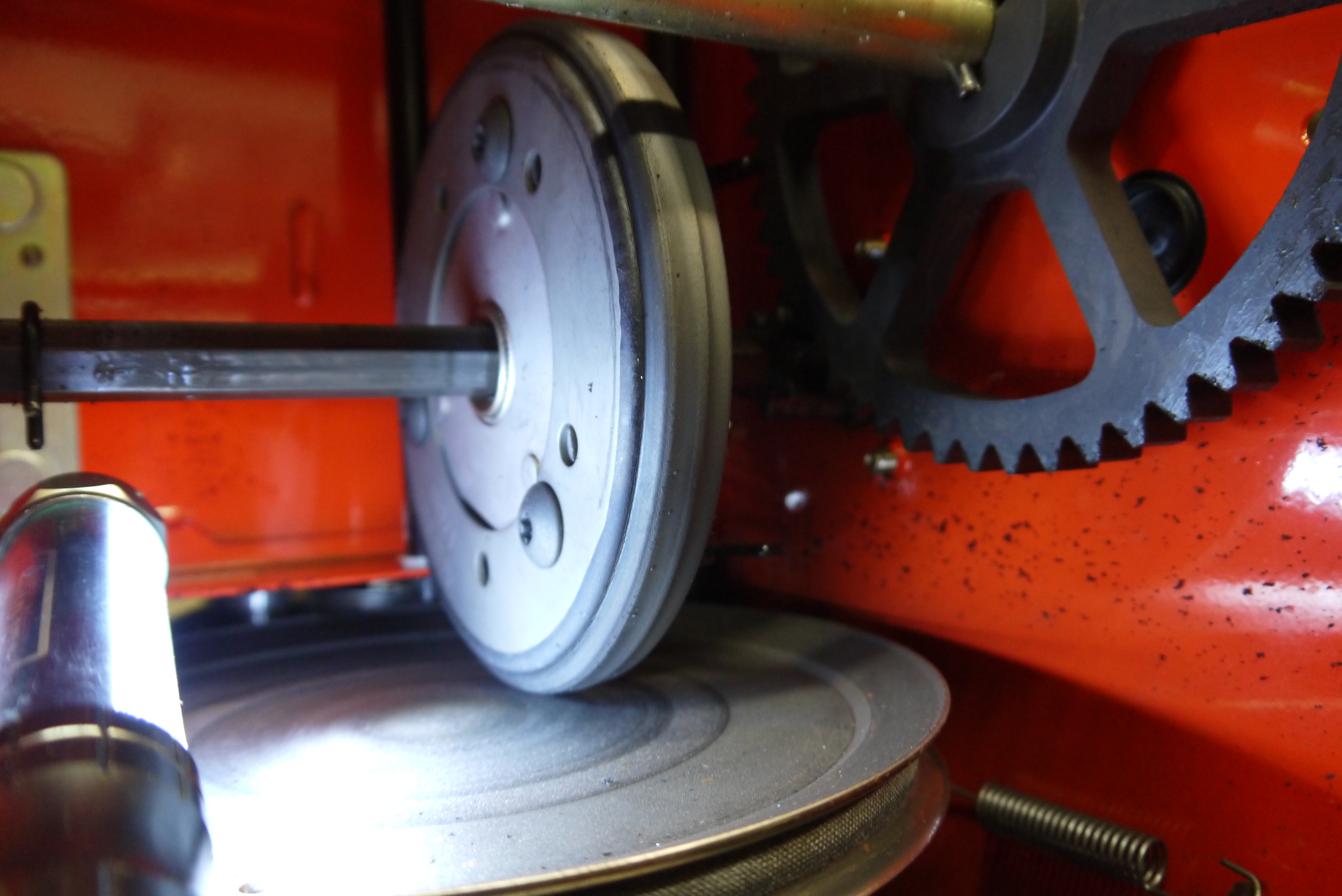
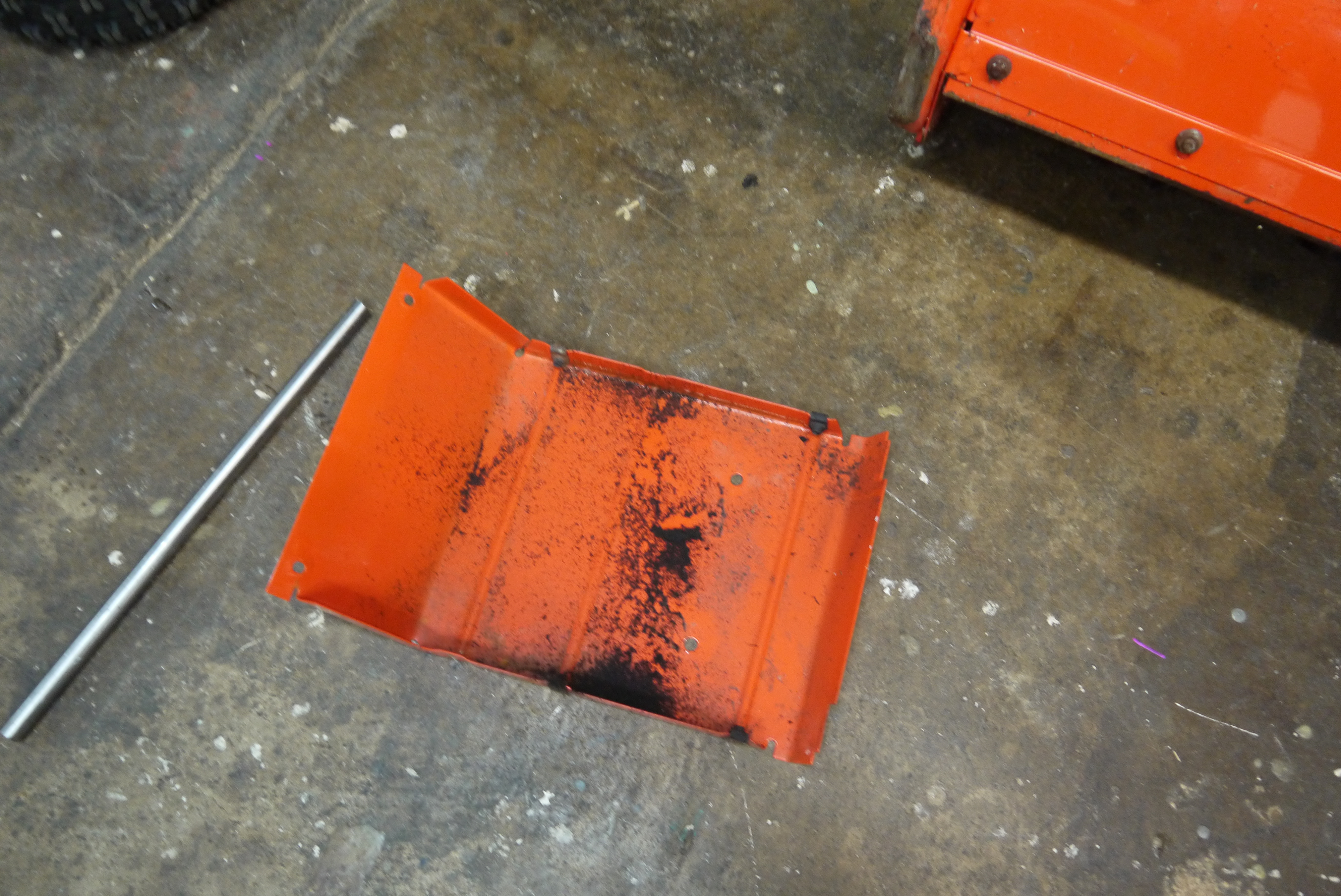
Resistive transfer wheelWhen I took off the back cover I noticed blackish powder (non-ferrous). It turned out to be from the rubber friction transfer wheel. When moving slowly the wheel is in the almost-center position, and at high speed its closer to the edge. Its purposely a friction transfer (spring loaded tension limiter with hand-operated clutch lever) such that if you head full-tilt into a concrete-paver the force transfer doesn't funnel back into the engine and disrupt operation. It appears this beast was in fact used for a bit! The transfer wheel (shown) does appear flat, indicating some use. 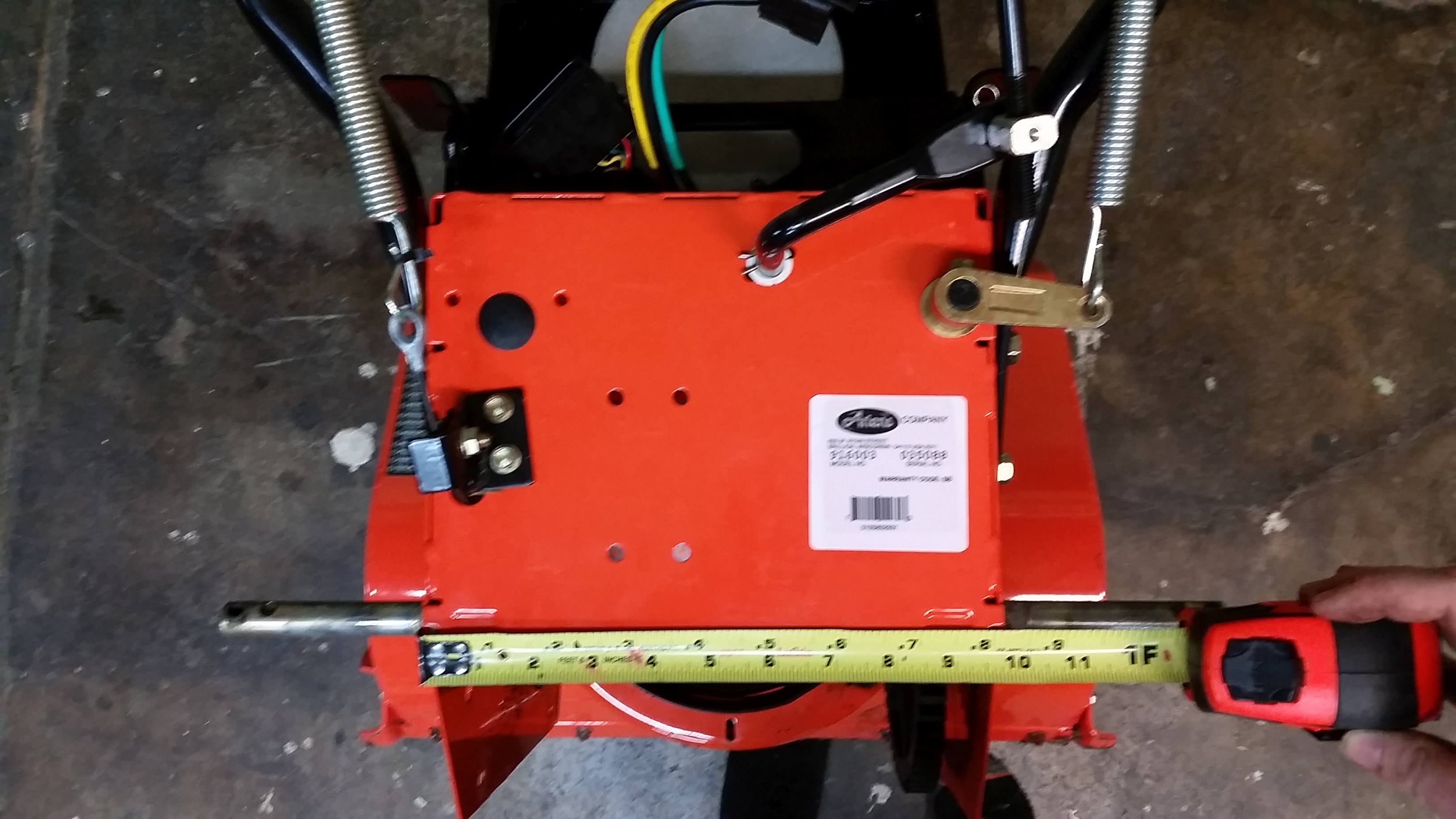
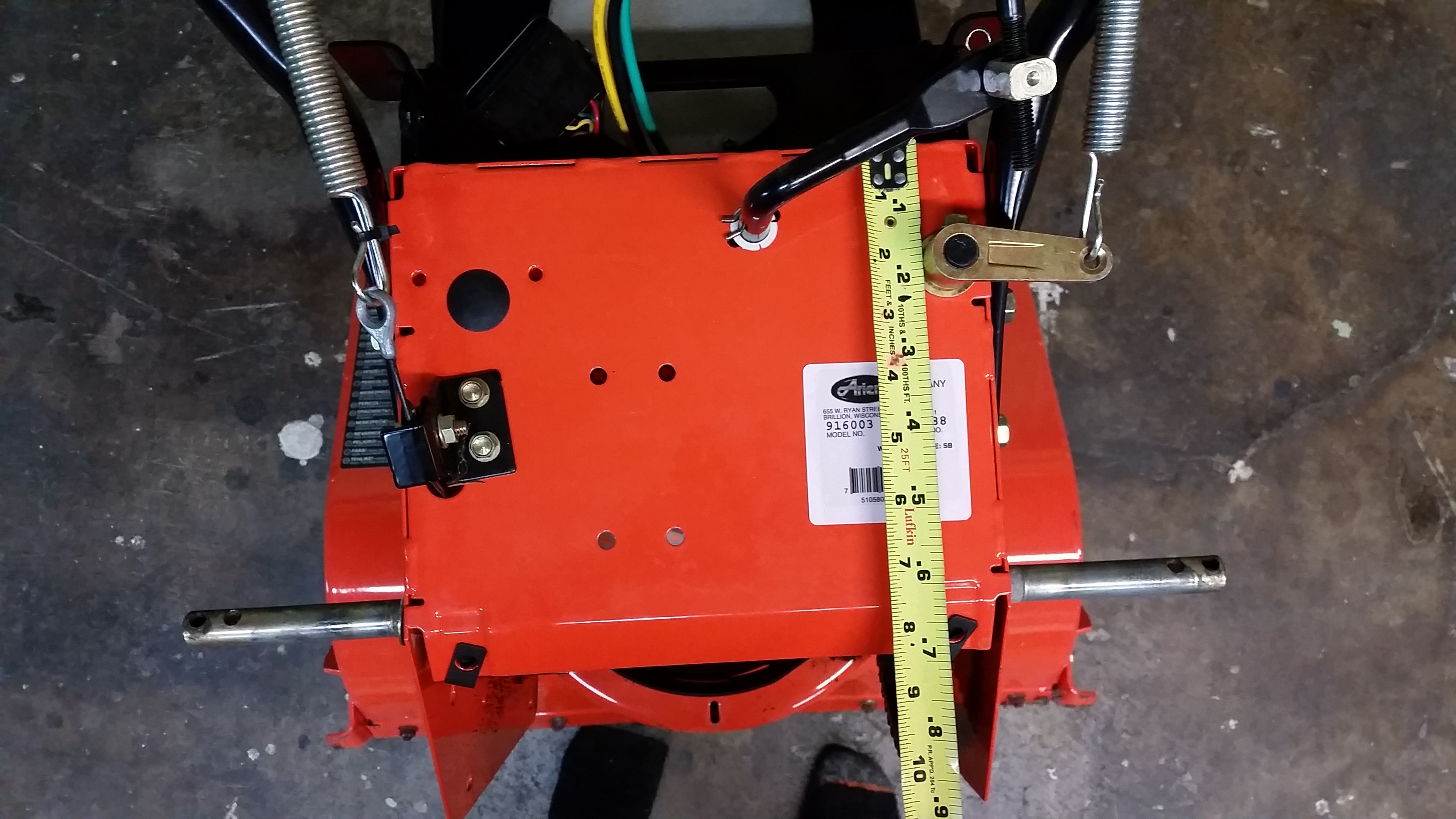
Double checking some sizes for 'upgrades'.The back panel has a few things sticking out, the tension lever for the impeller, the power transfer for the previous friction transfer wheel and a spring tensioner that went to the handlebars. Only the golden-colored tensioner was still needed, but at this point i wasn't sure if I would want to revert back to its previous state. 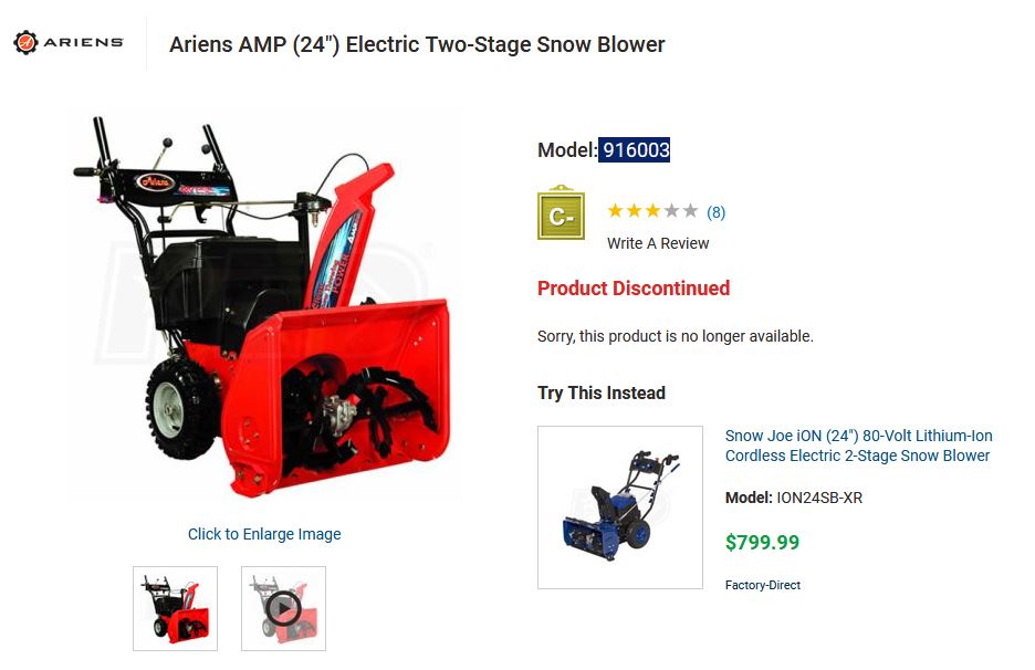
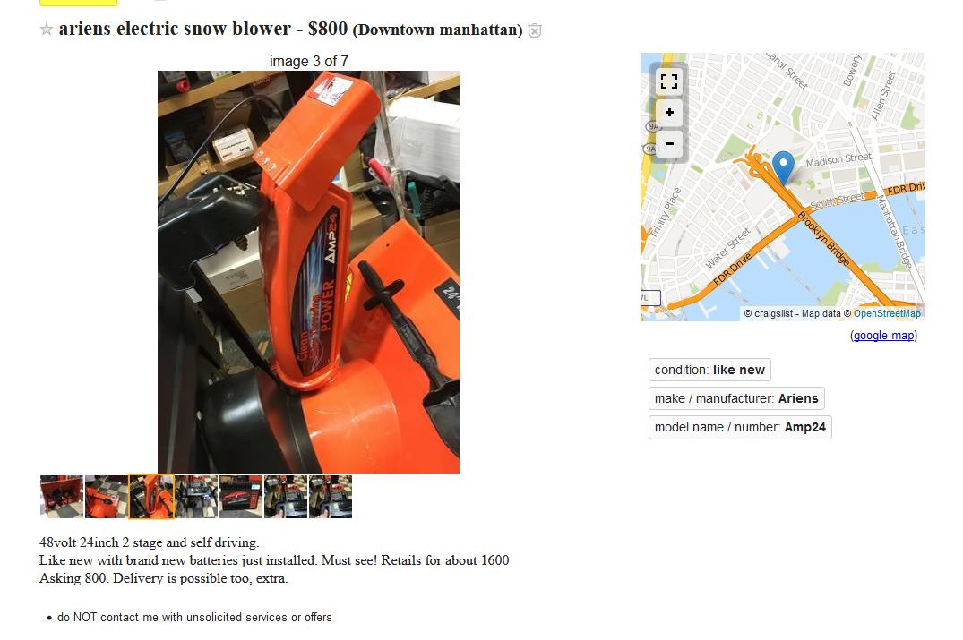
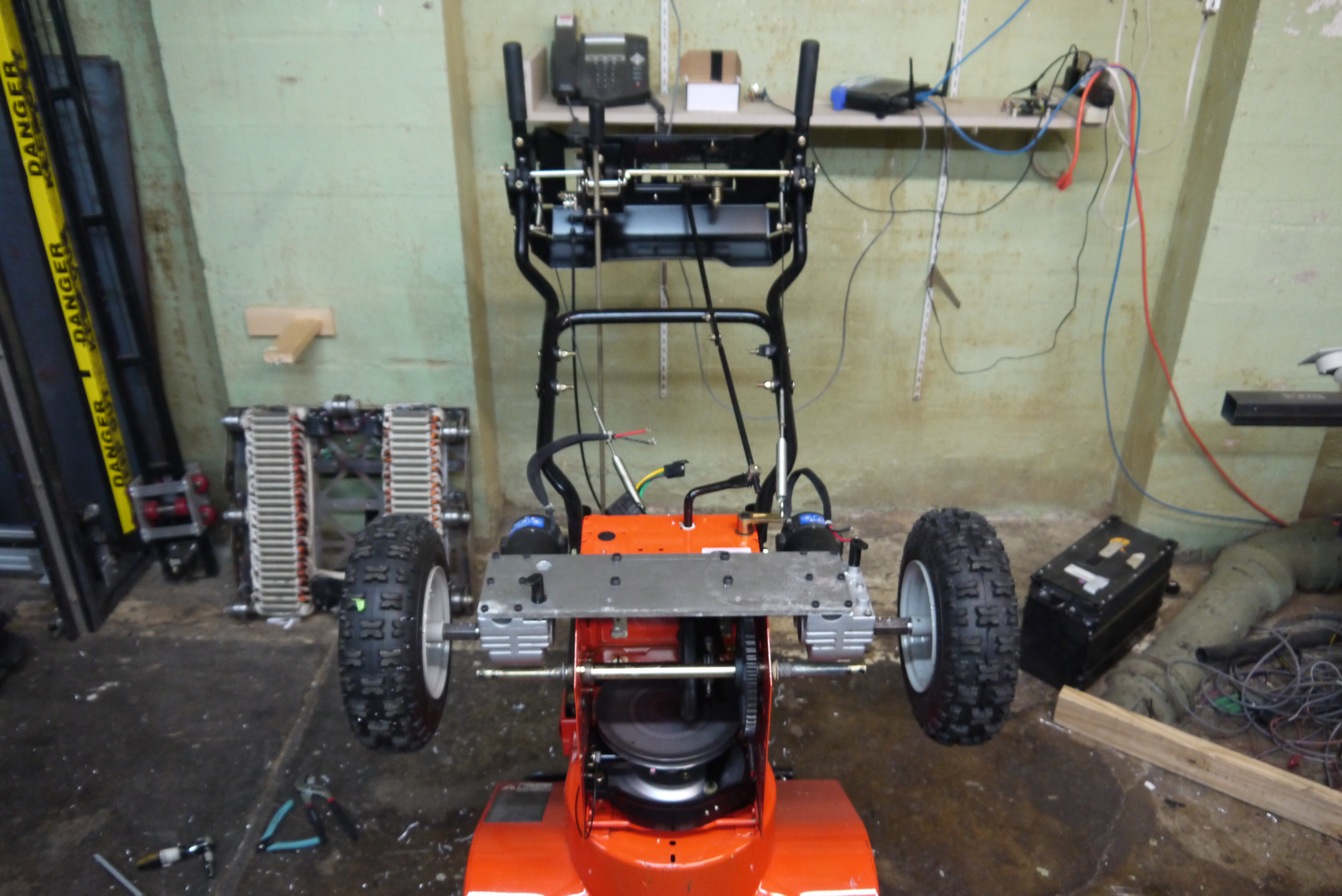
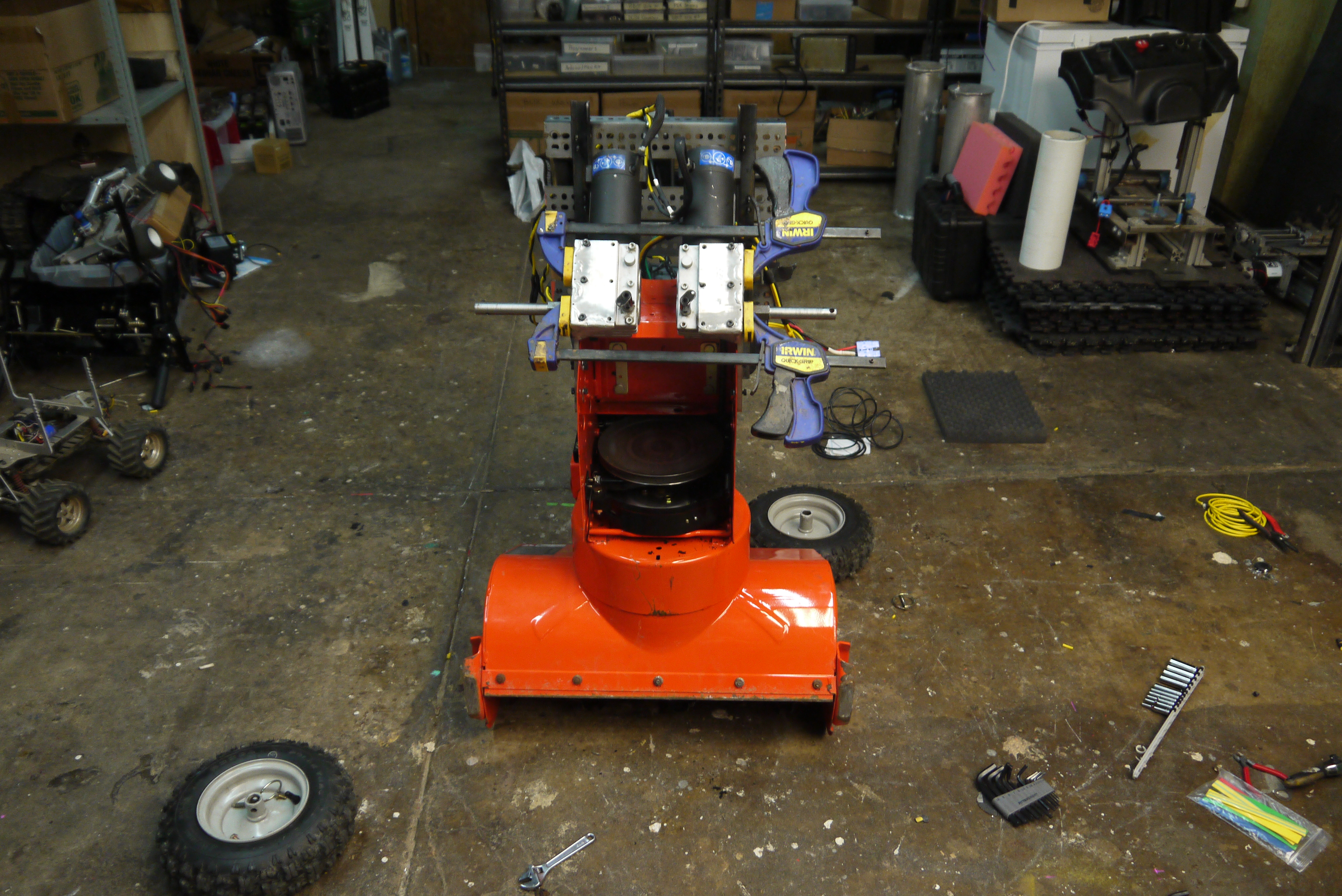
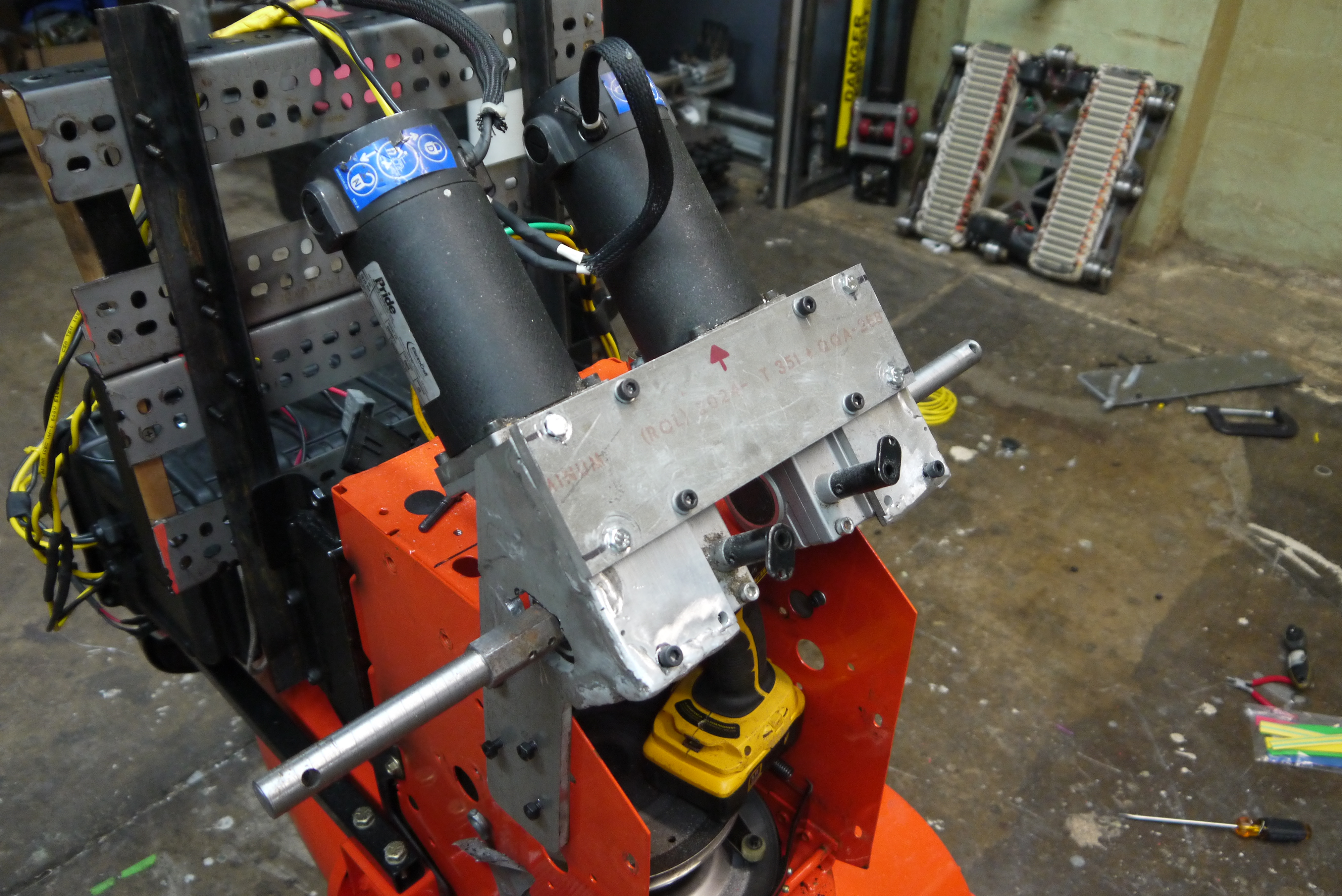
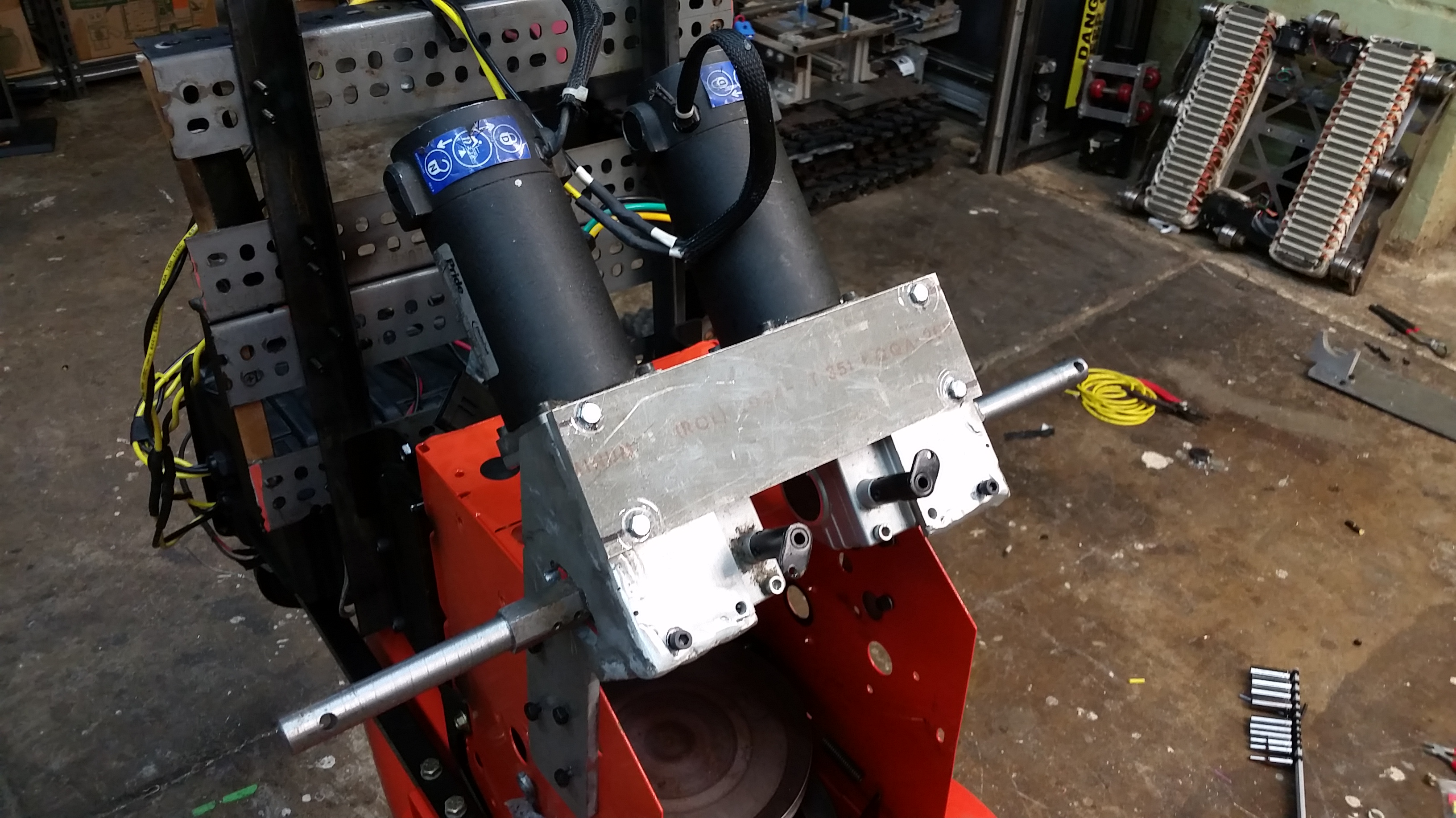
How much does this thing normally cost?Snowblowers are a weird creature, sometimes only used in an incredibly low duty cycle, but can be quite expensive. I looked around, and while the product itself is discontinued, there seem to be a few hiding on craigslist periodically. Quite a curious unicorn. Version 1 robot-if-ication: Quick propulsionMy plot was simple, the great storm was coming: Bolt two wheelchair motors along the sides with a big plate and test it out in the snow: Develop a better wheel mount as time allowed. Note that I did not have the stock wheelchair wheels or shaft adapters, so there would be a bit of work to do to mate these together. 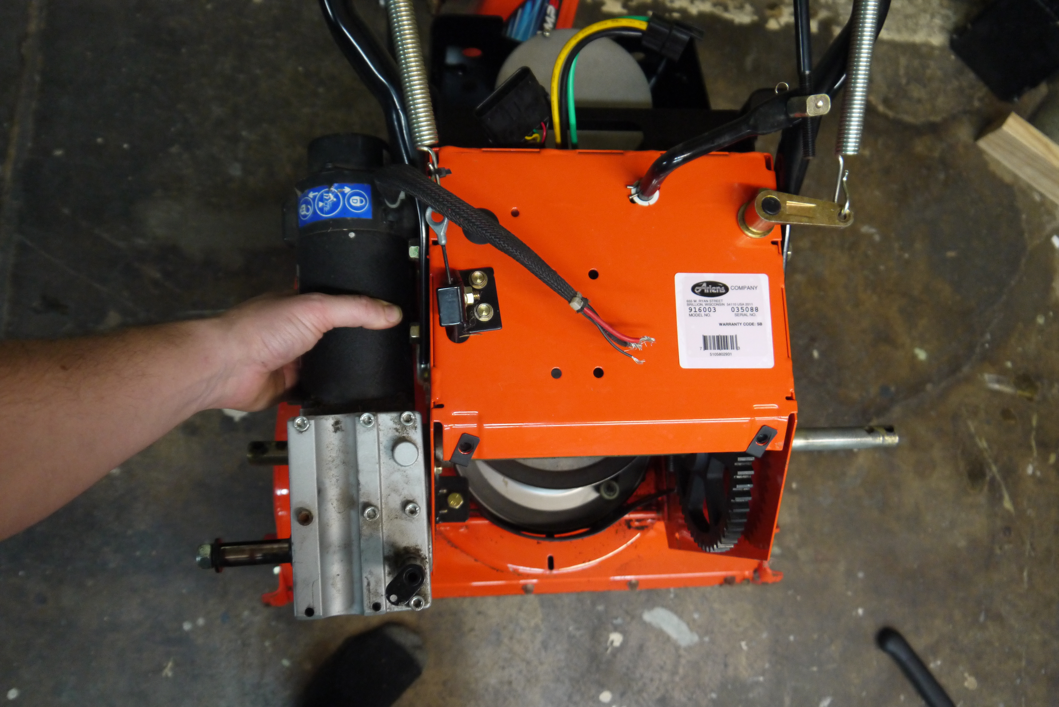
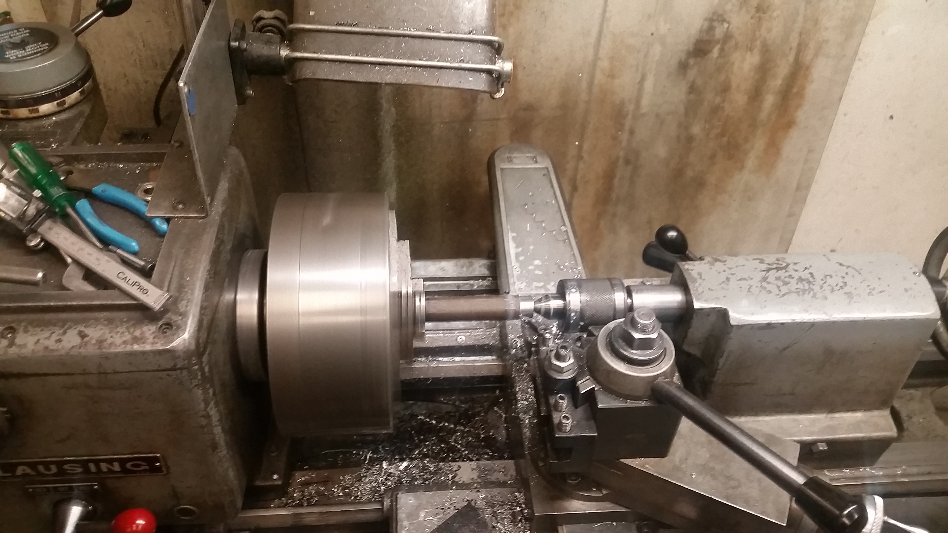
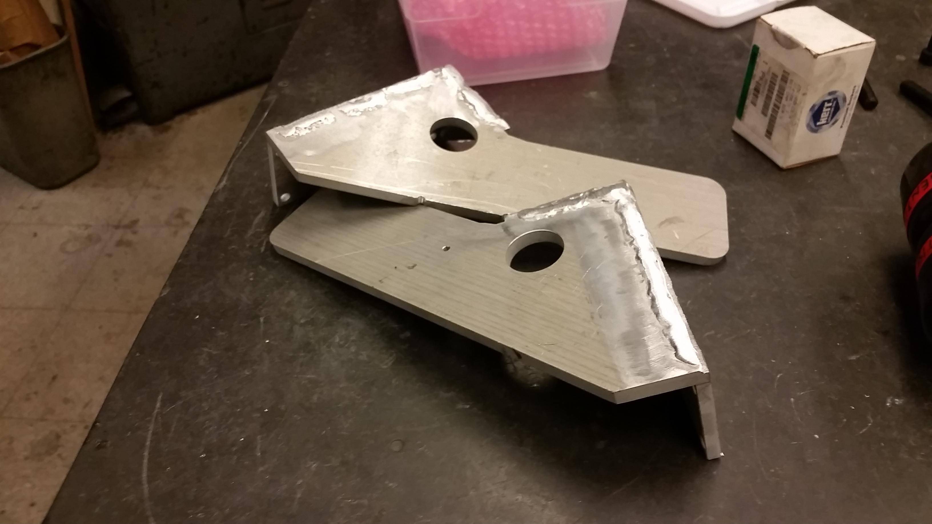
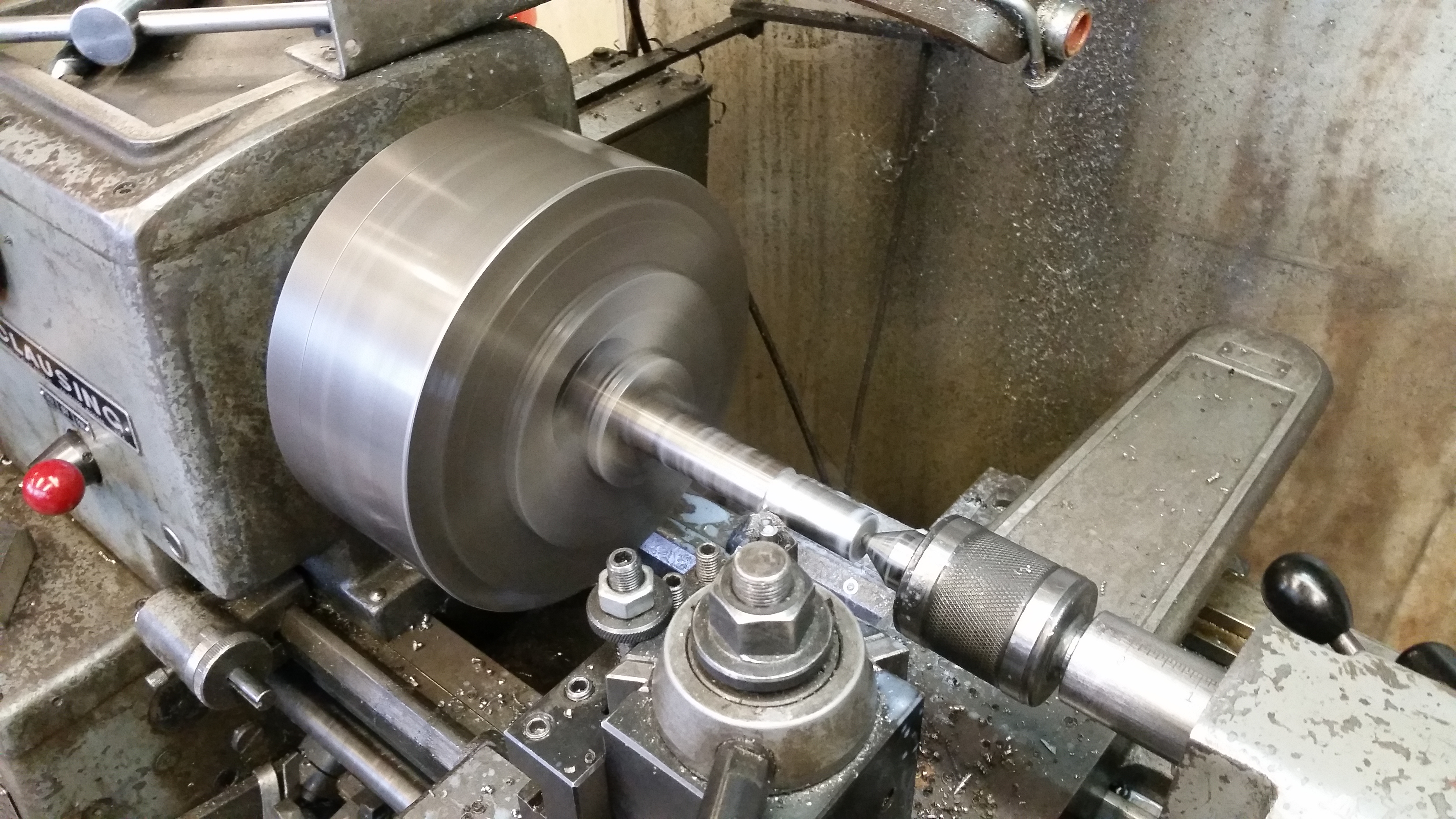
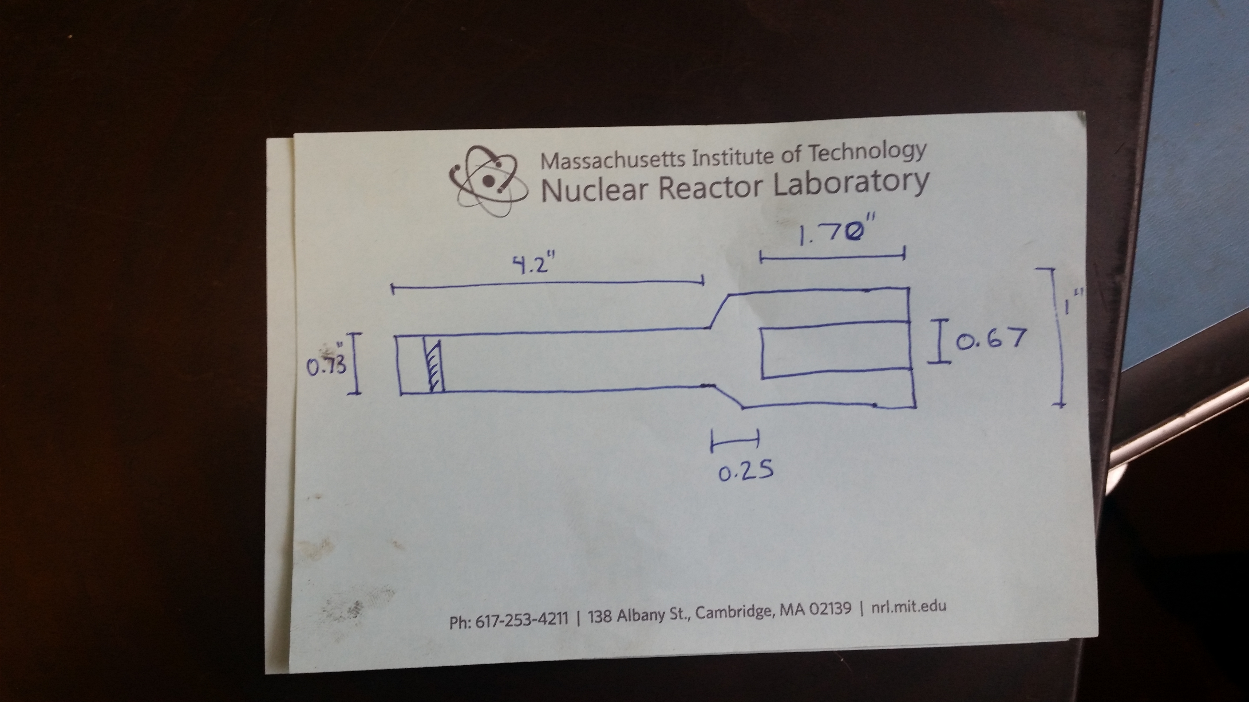
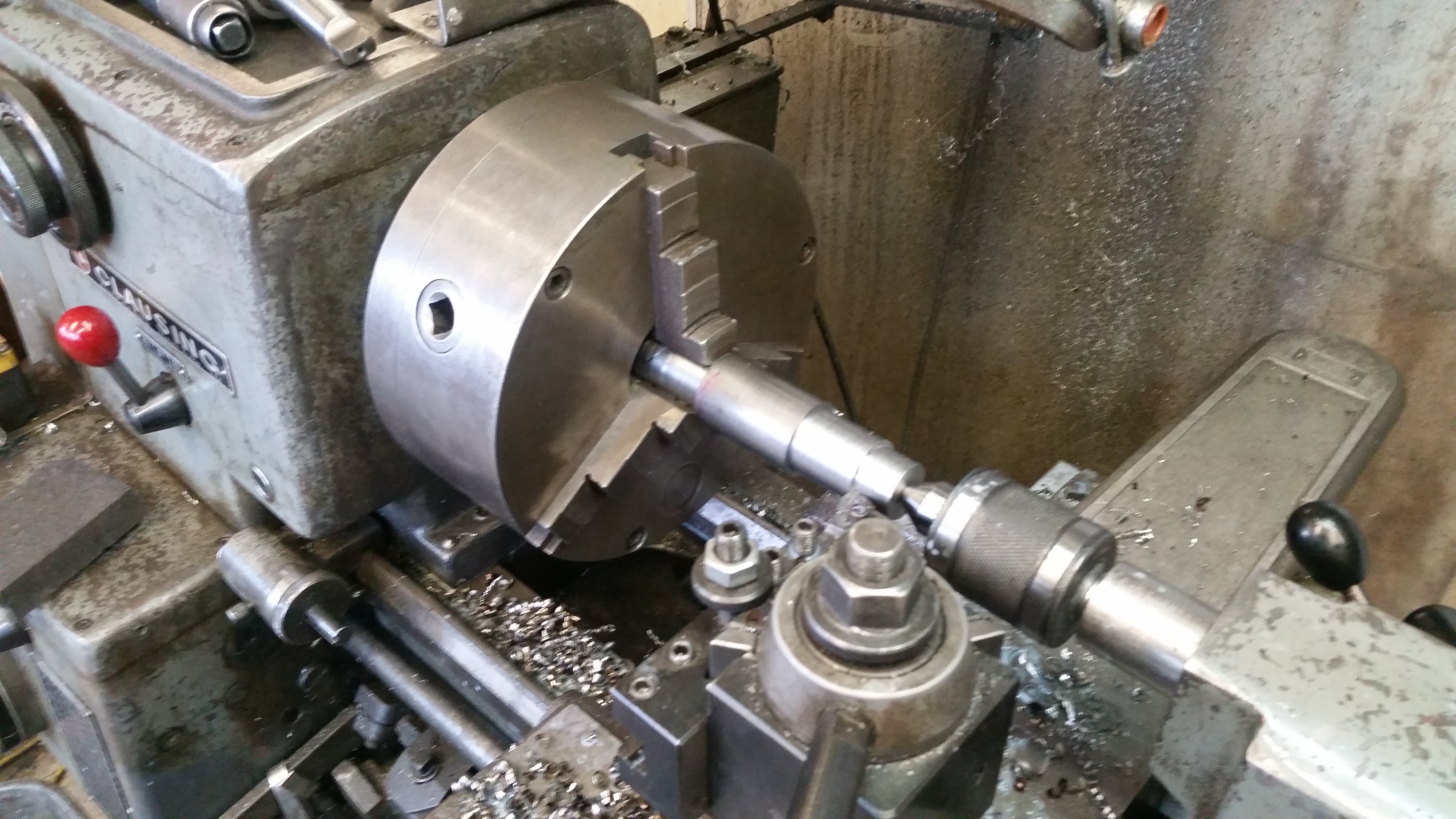
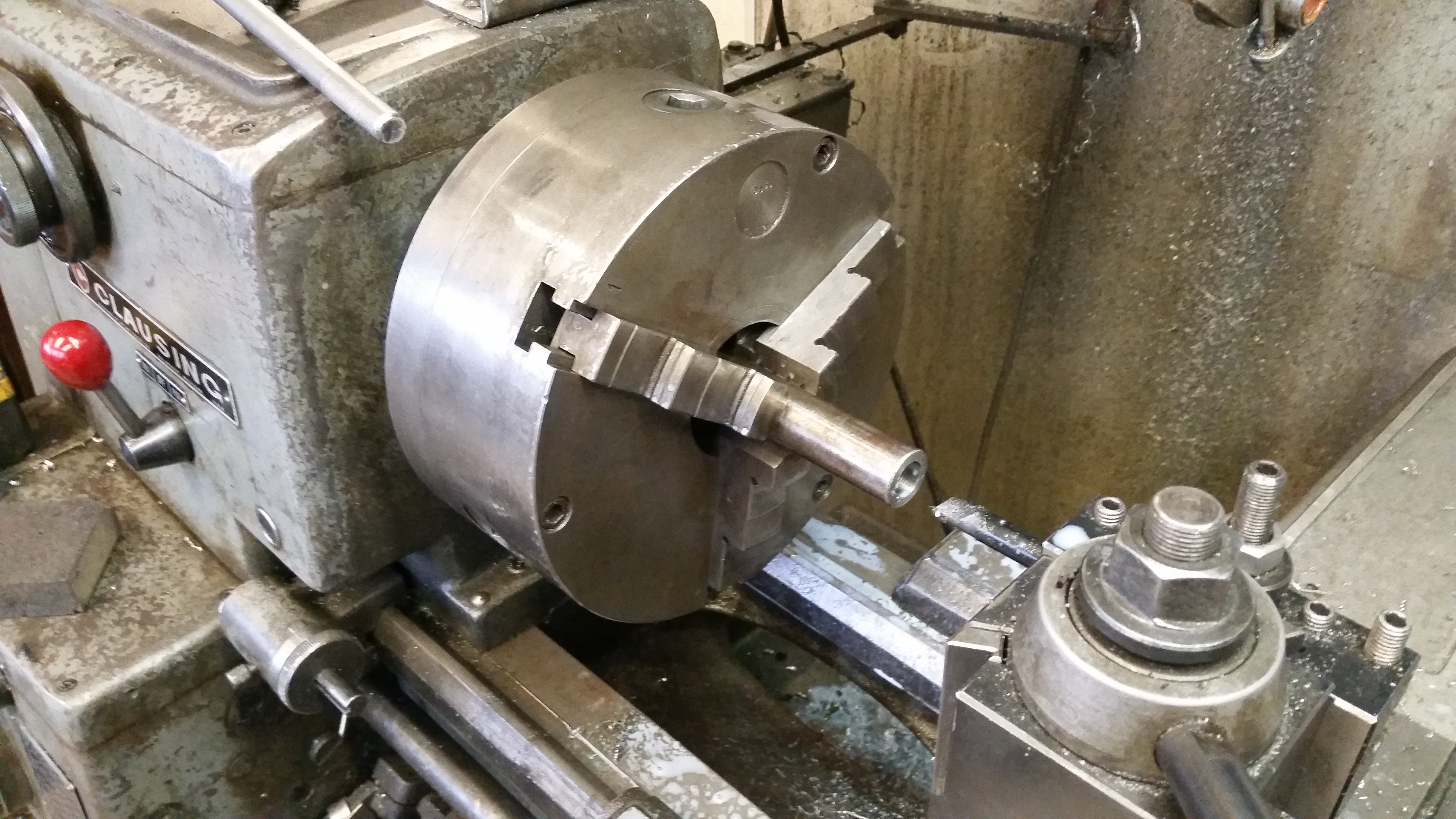
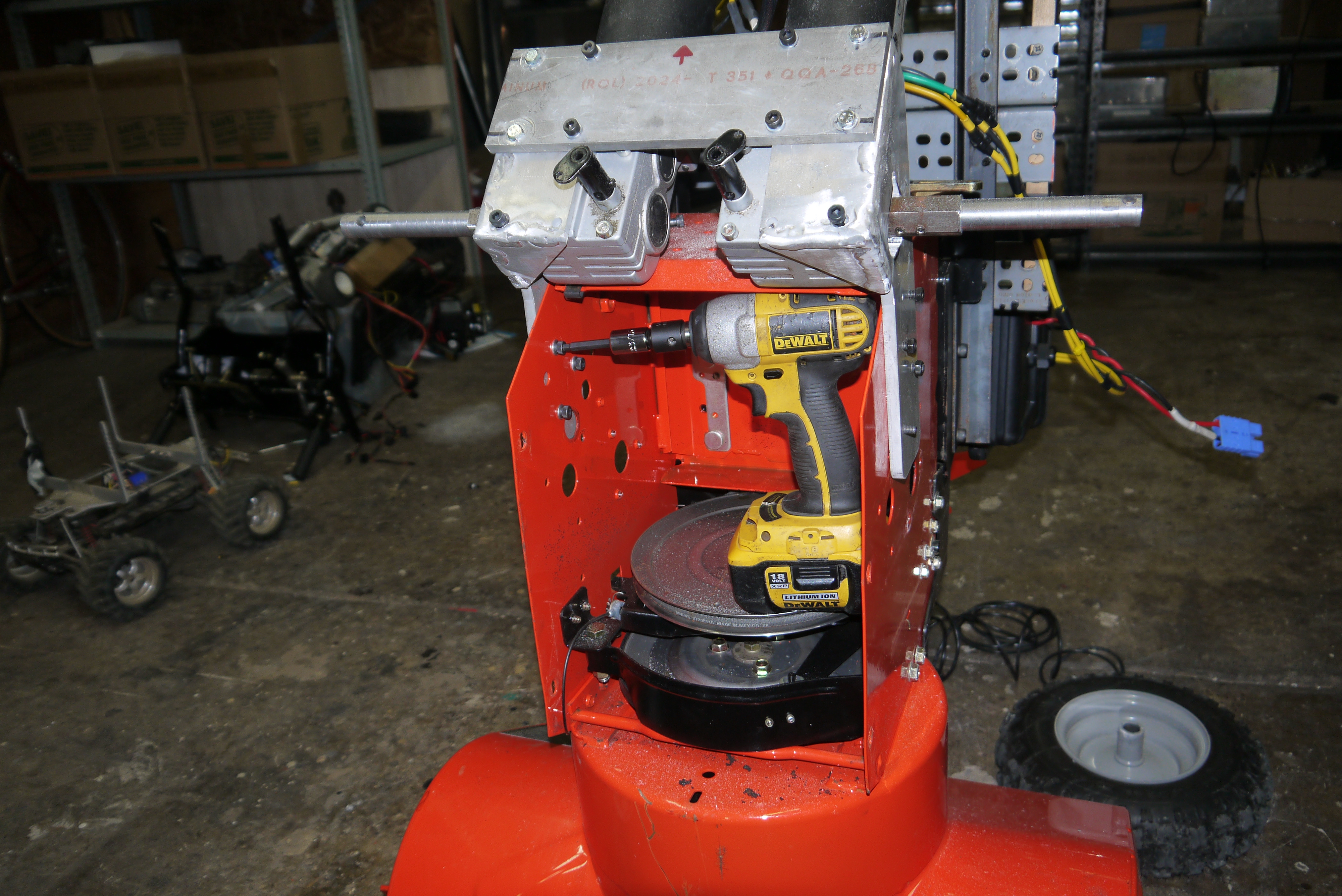
For the shaft adapters I started with some scrap hex-stock, I turned down one side to fit the wheel ID and counter-bored the hex-side to fit the wheelchair motor shaft. Miters lathe made quick work of the mild-steel hex-stock 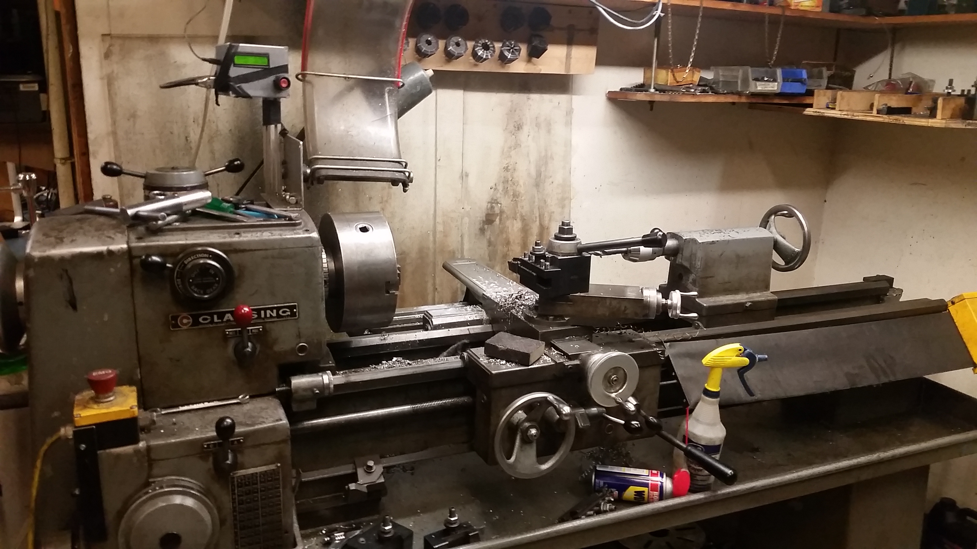
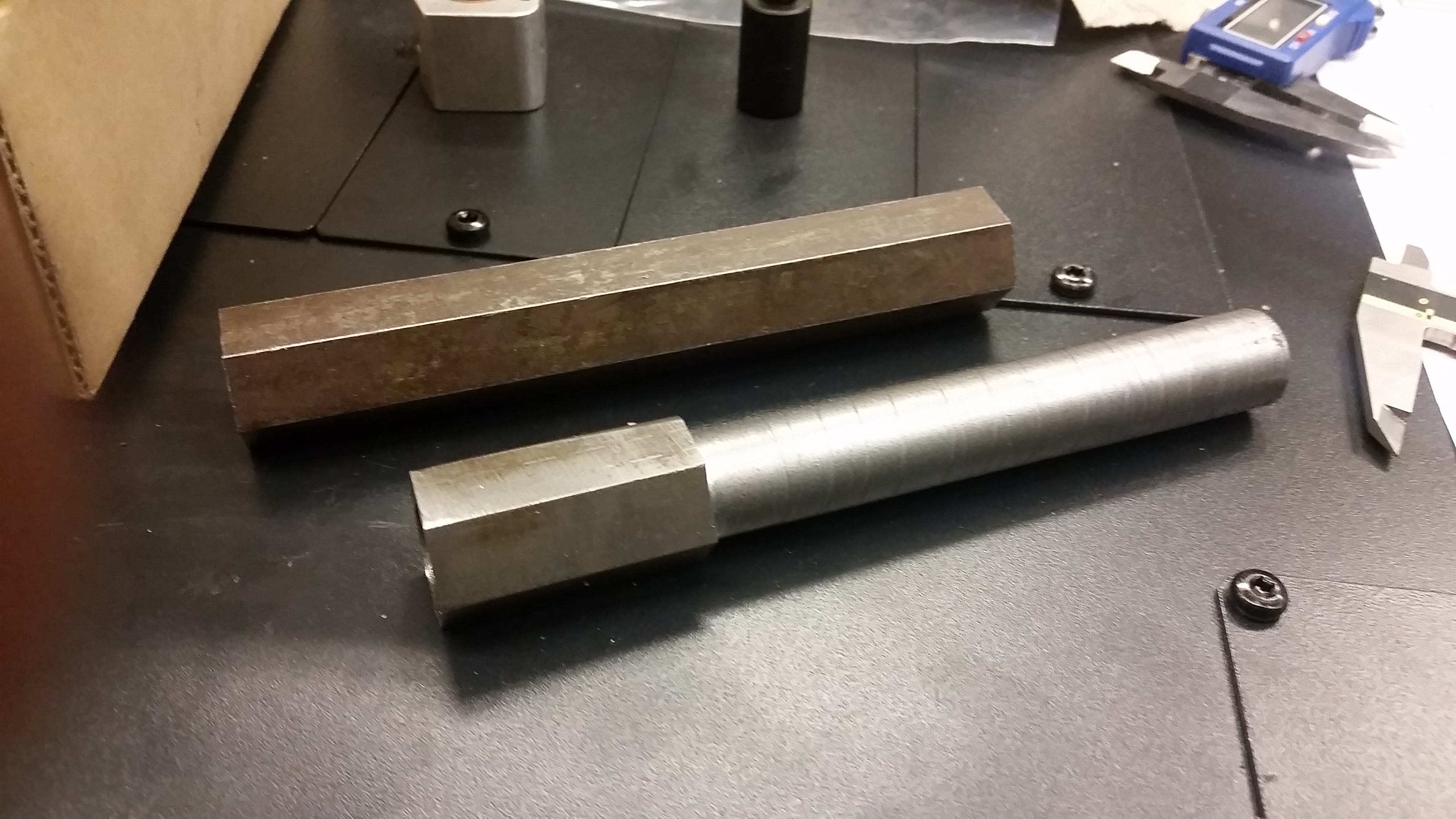
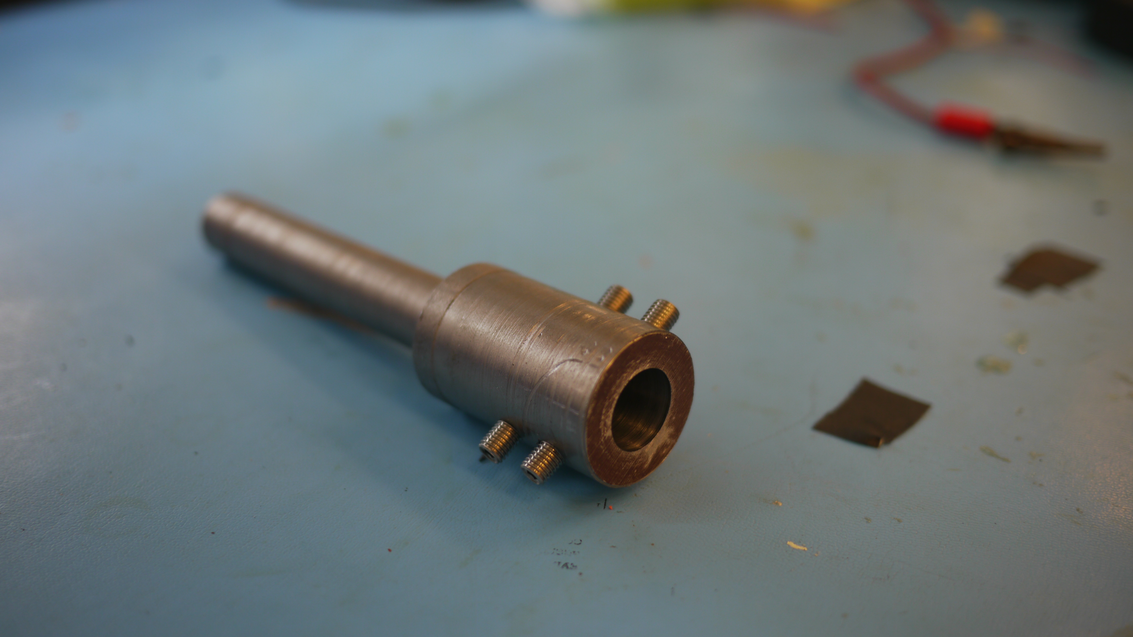
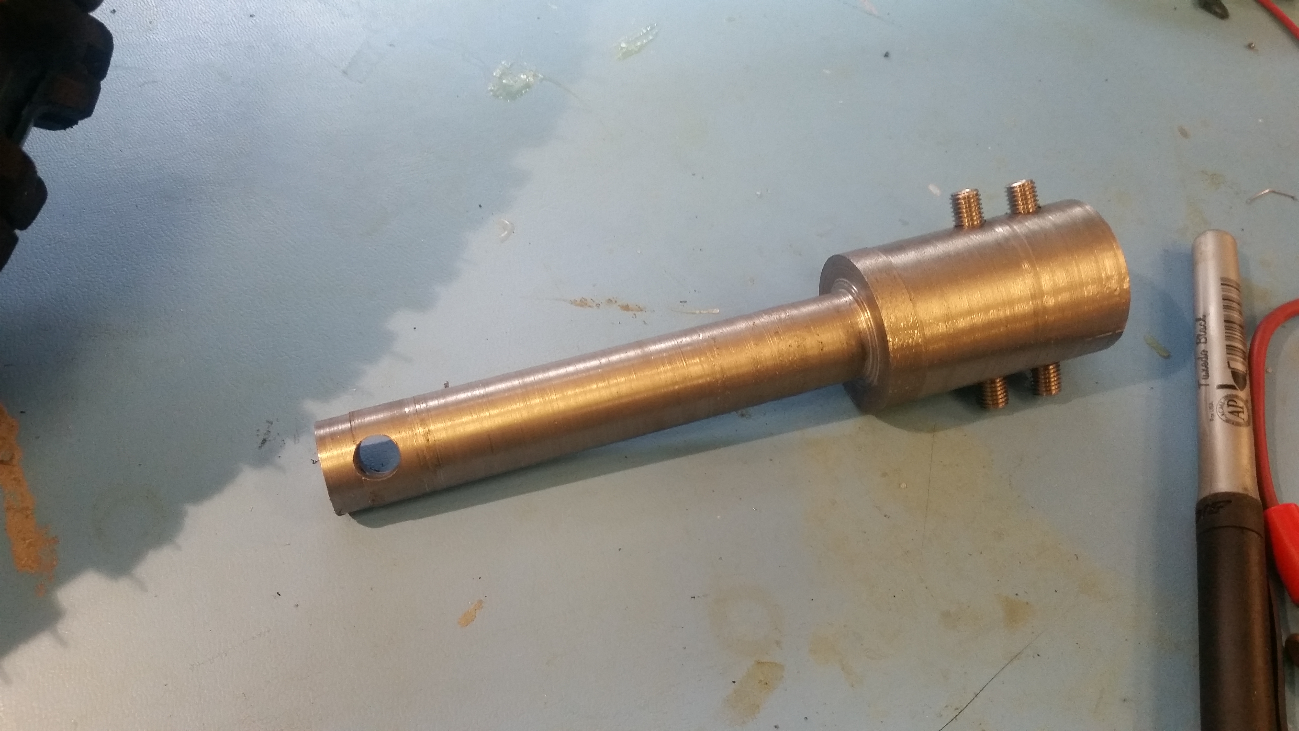
Here's a before-and after, these are the 'night before the storm' shaft adapters. I went a bit overboard counter boring the wheelchair mount shaft such that there's a bit of a thin-wall between the ID of the wheel and the OD of the wheelchair motor. 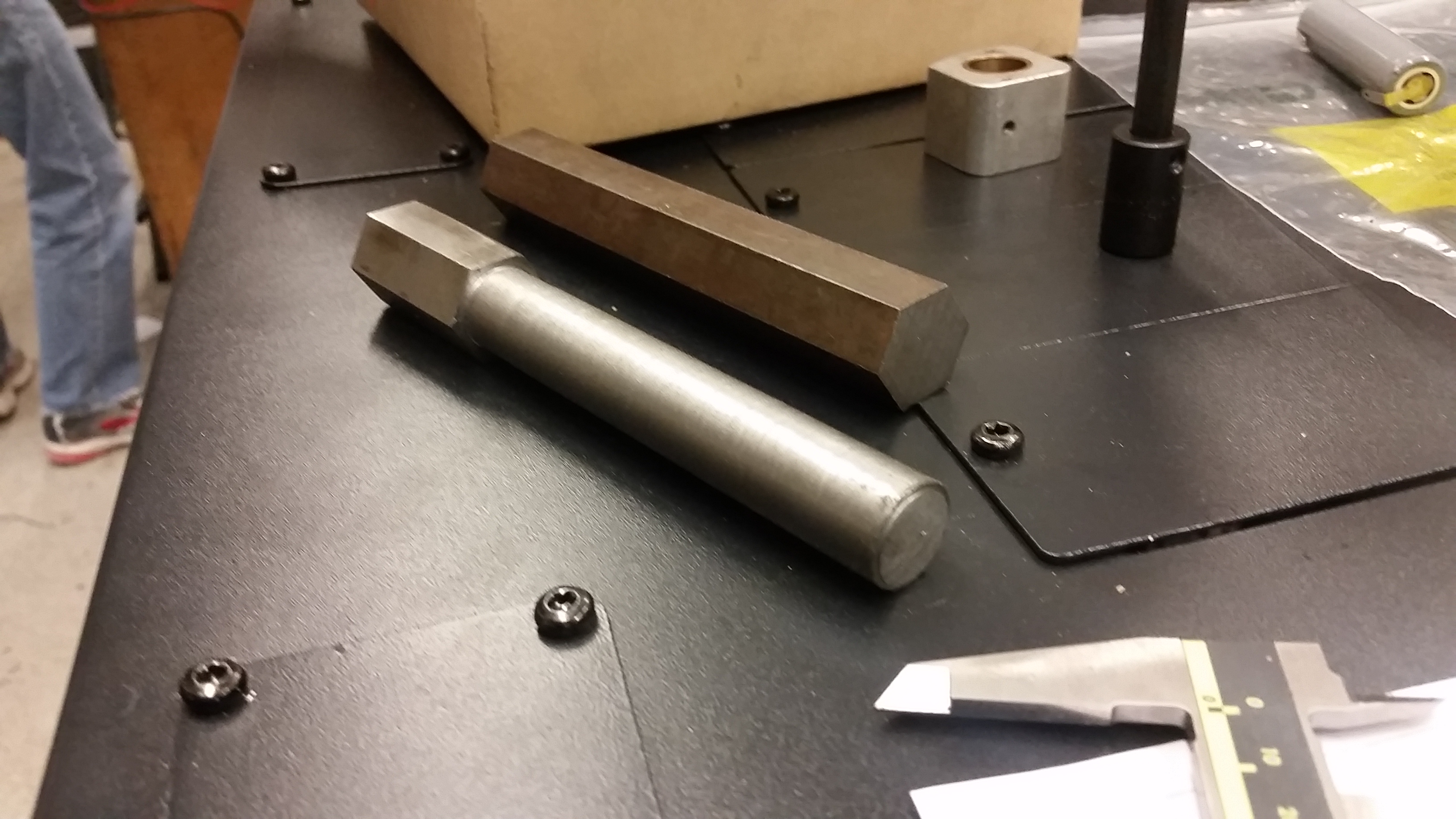
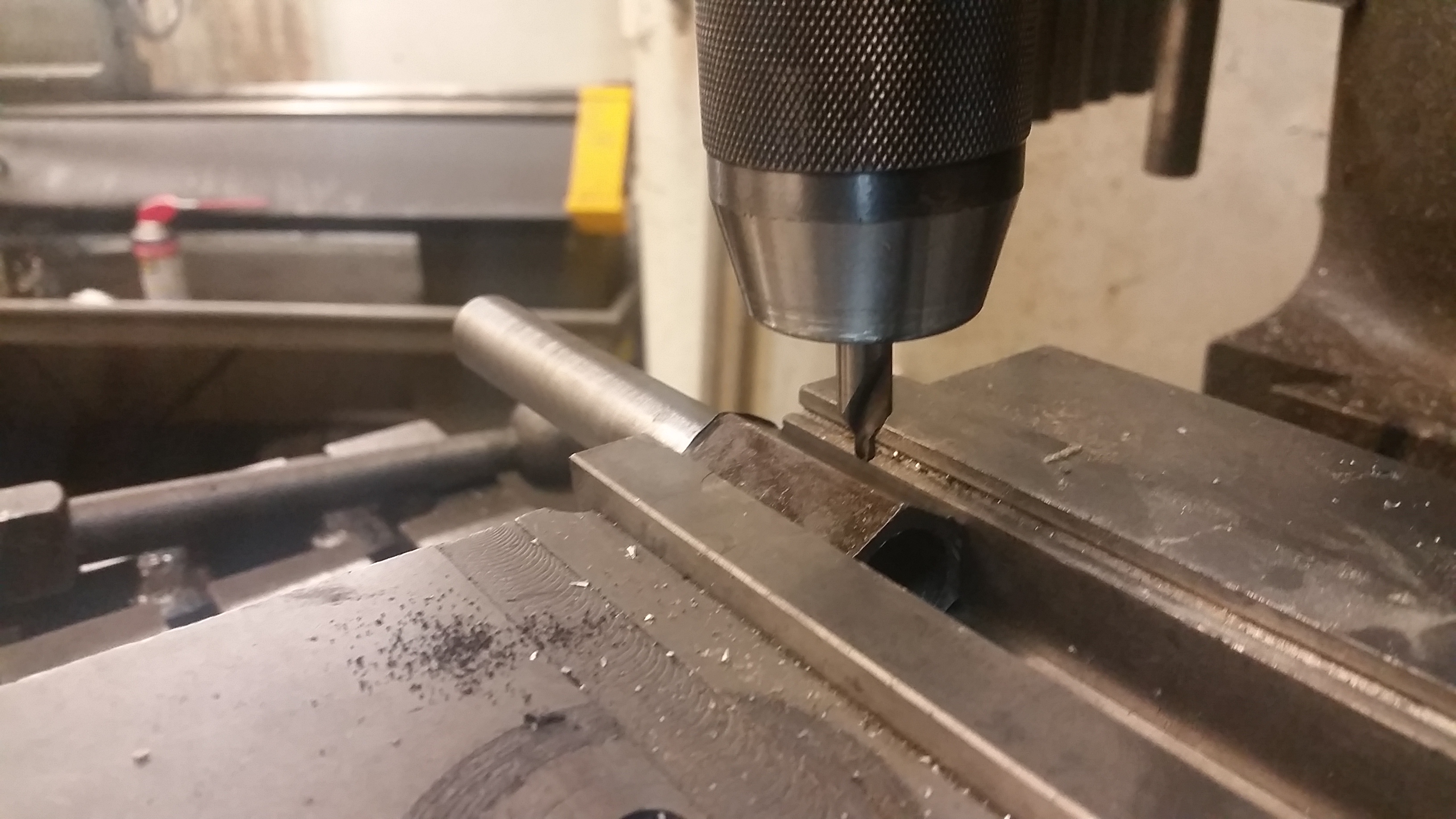
Next up, two tapped 1/4-20 holes to interface the shaft adapter to the wheelchair motor. I used four 1/4-20 set screws and green-loctited them in place. The counter bore kept everything snug and concentric. 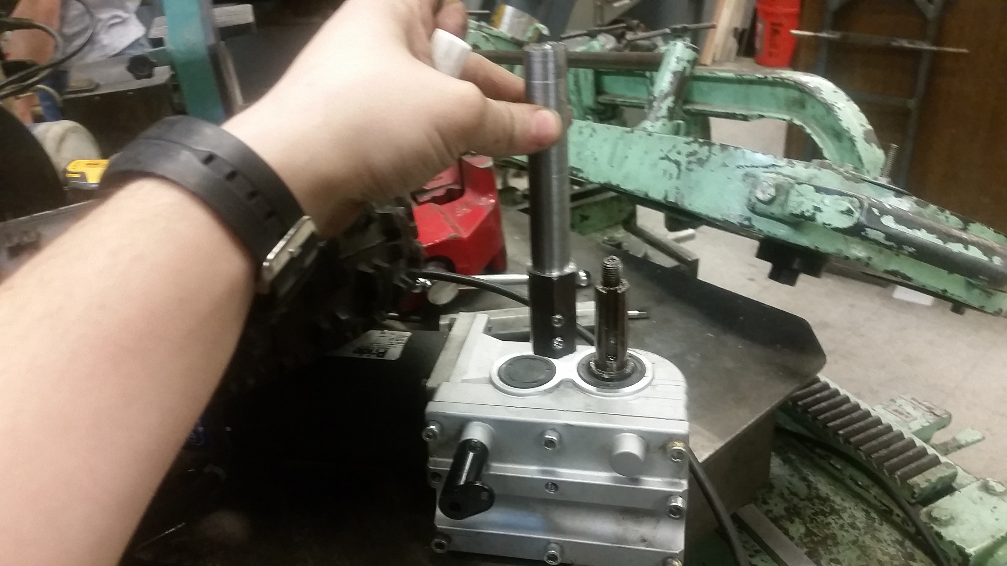
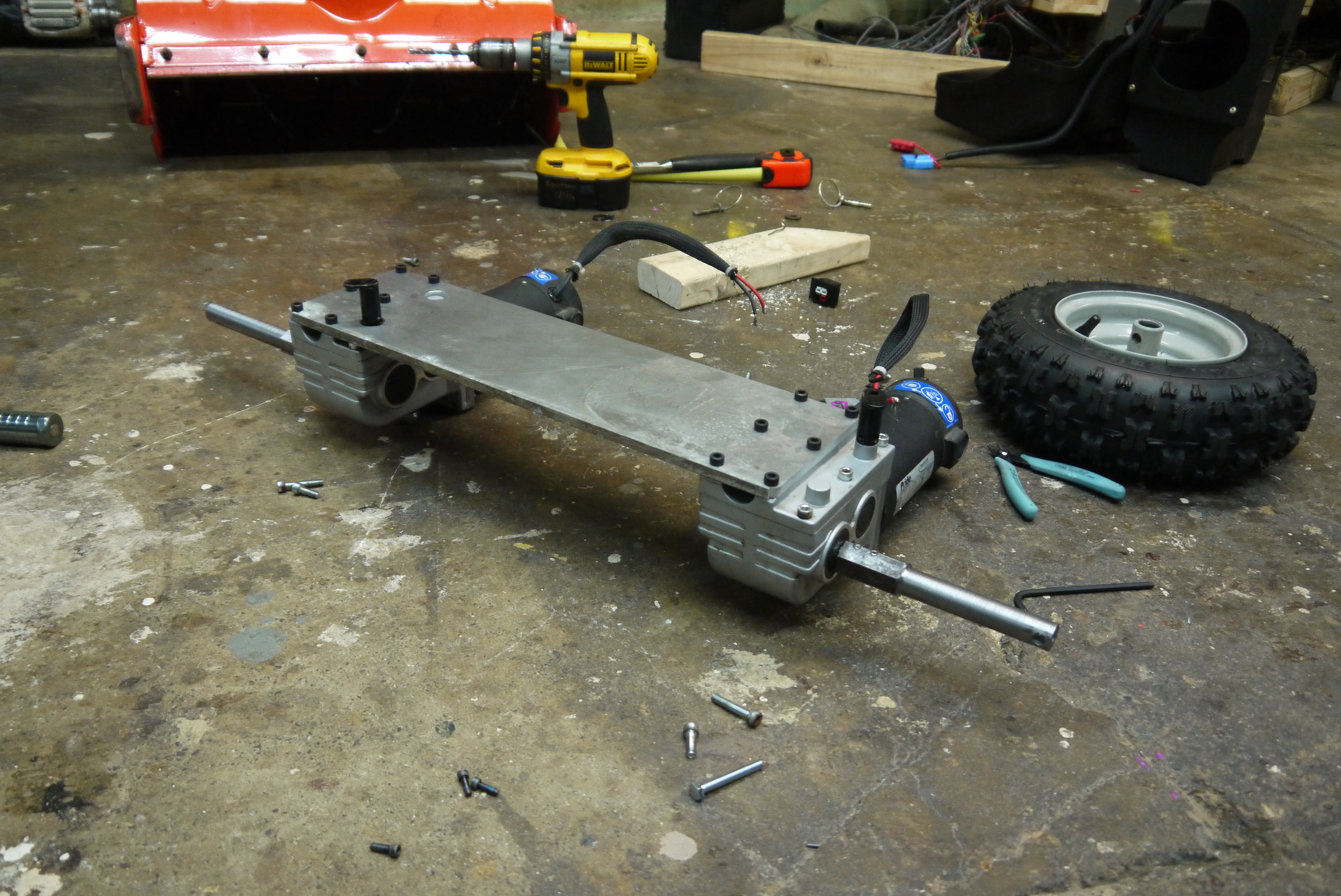
With the two shafts complete, time to mount the propulsion and build up the drive electronics. 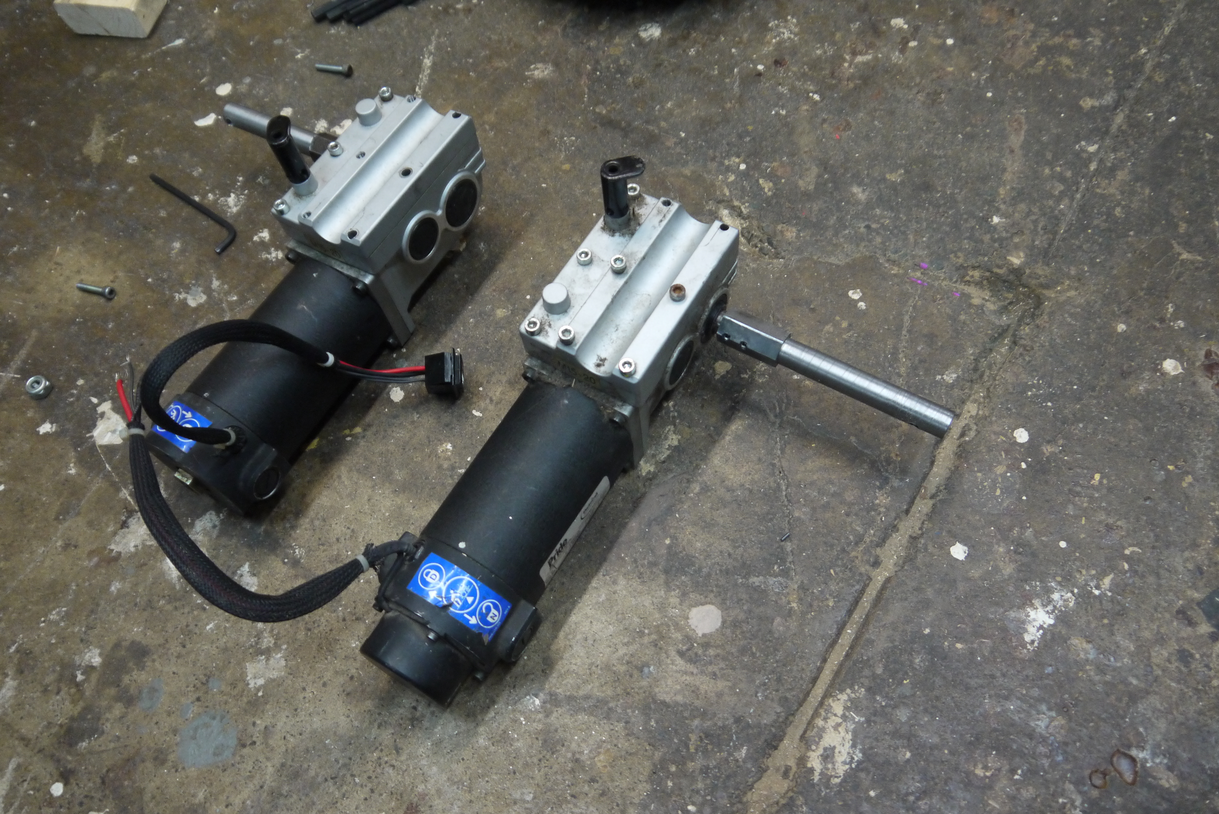
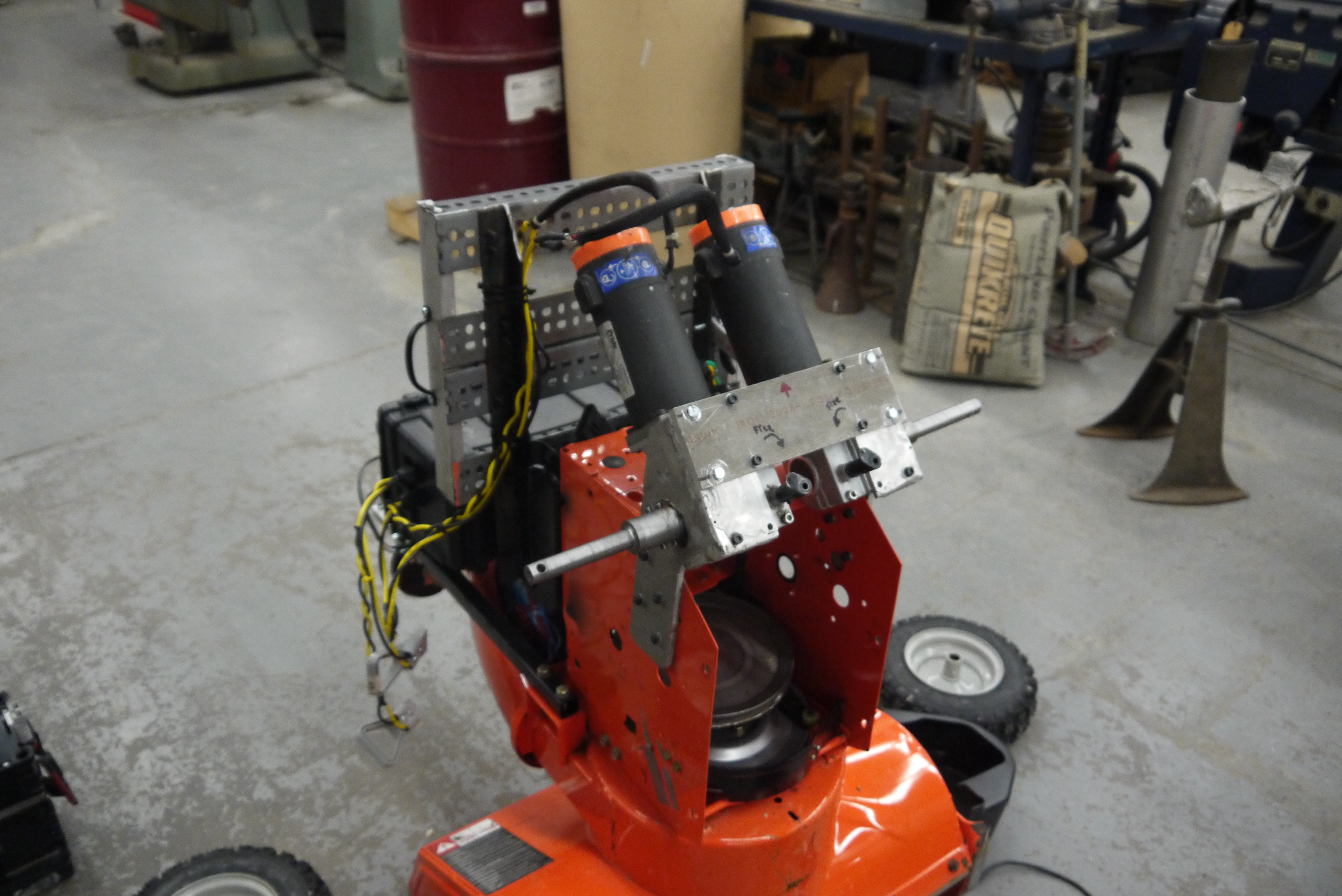
A large aluminum plate was used to attach the two motors to the snowblower. This was the 'super simple' route. Interestingly the two wheelchair motors were at once a pair, however, when I was taking dimensions for CAD drawings, I had placed the back plate on one in reverse. This surprisingly didnt affect the gearbox as much, just the break-enable lever was affected. Once I realized this i ended up swapping he plate around and drilling new holes. 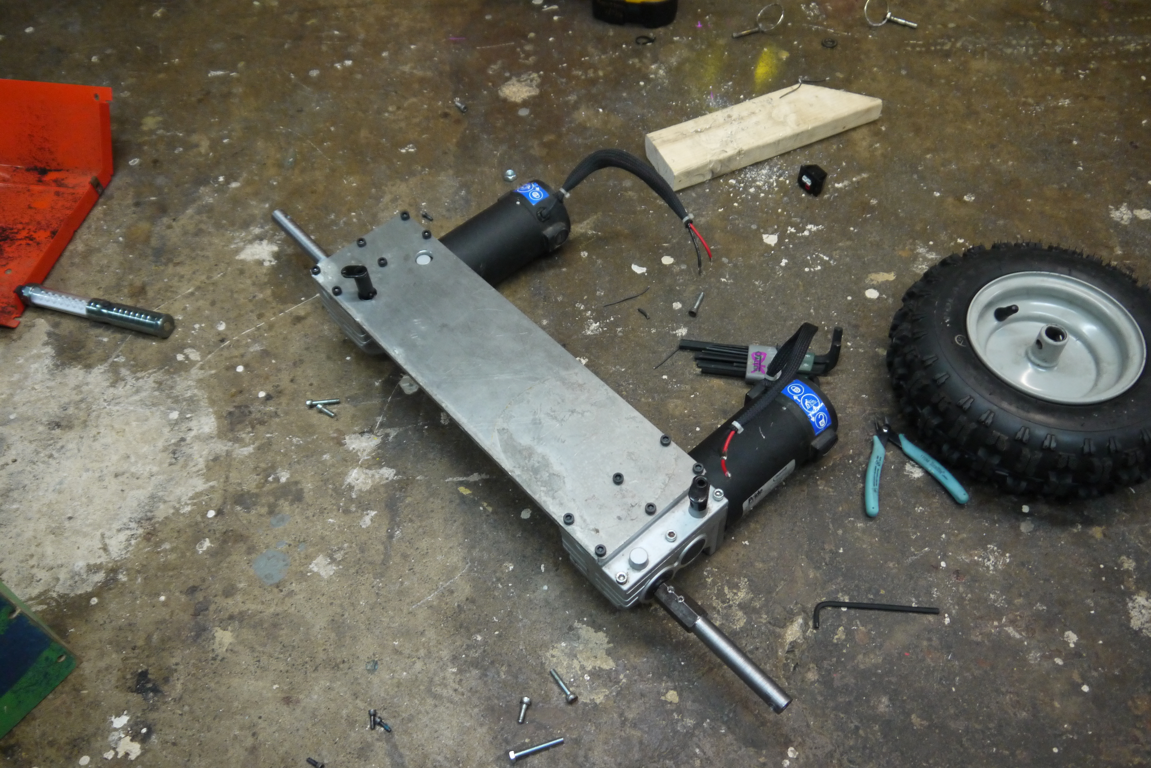
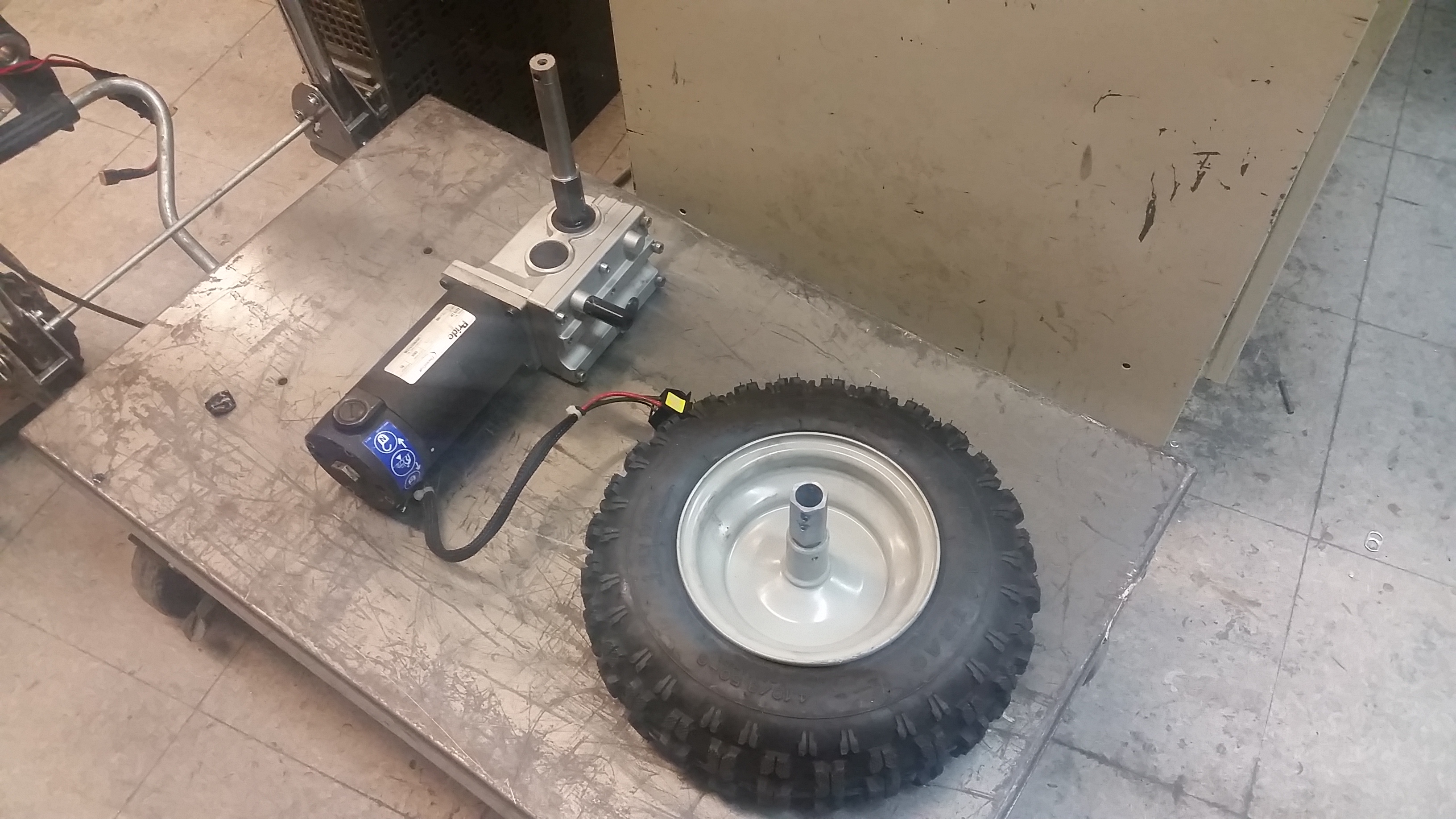
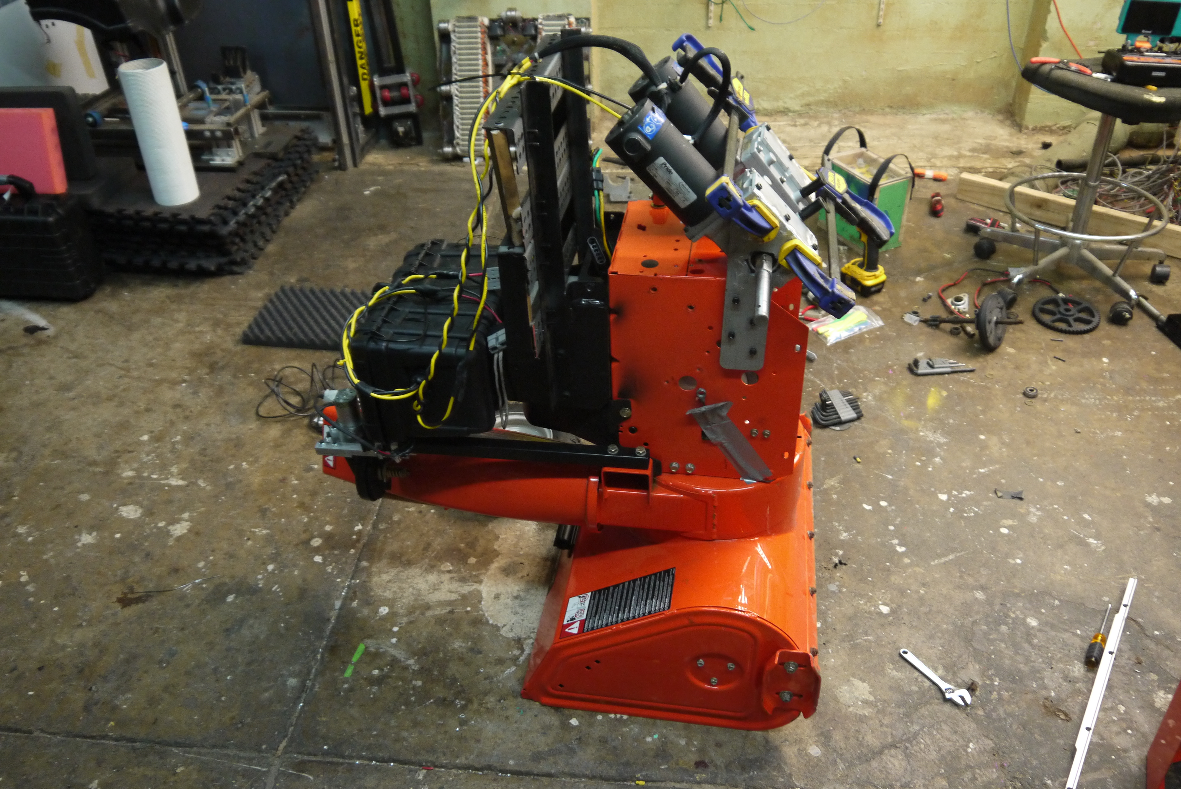
Mounting the wheel assemblyHoly moleys this is wiiiiide. I didn't initially want to remove the stock drive shaft, namely due to time constraints, so they remained. 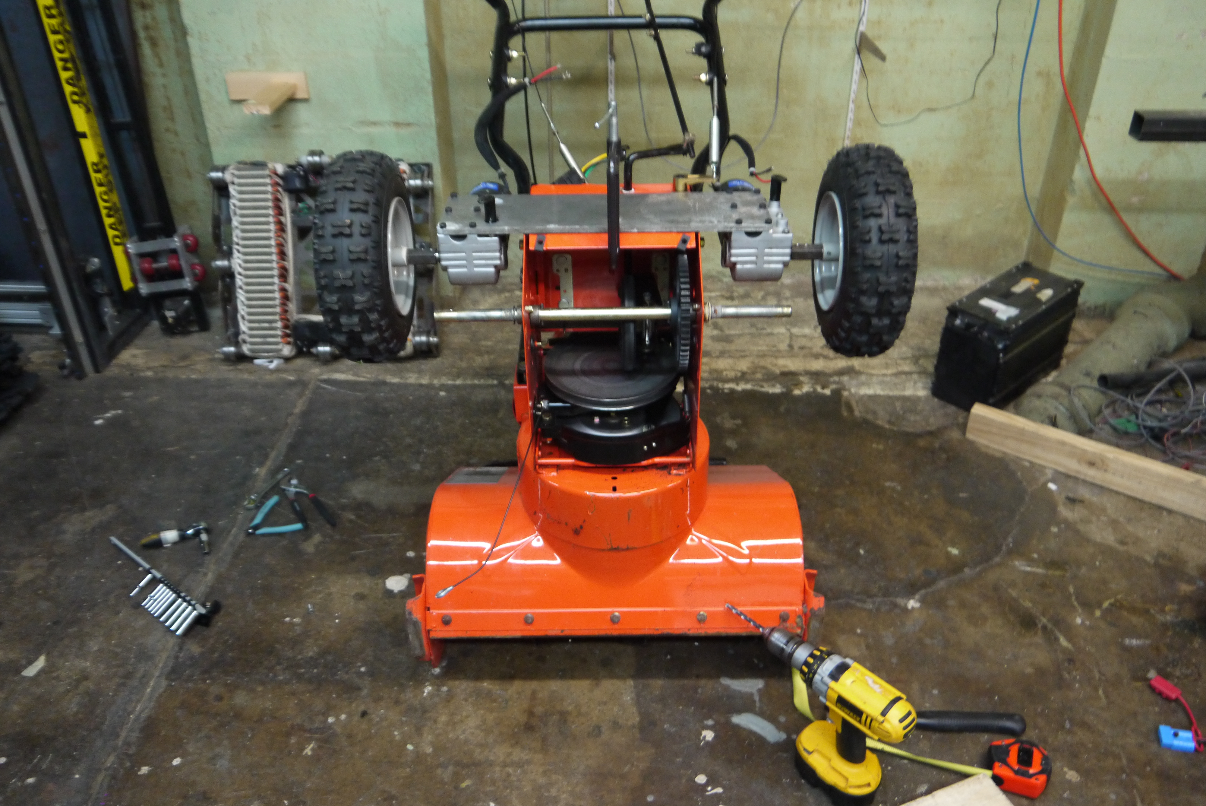

Shown is the whole wheel assembly from the side. With the wheels mounted and pinned in place. There's a bit more of a lever-arm on the shaft adapters than I'd like, placing un-due loading on the internal wheelchair motor bearings. Its also apparent how wiiide the wheelbase is. 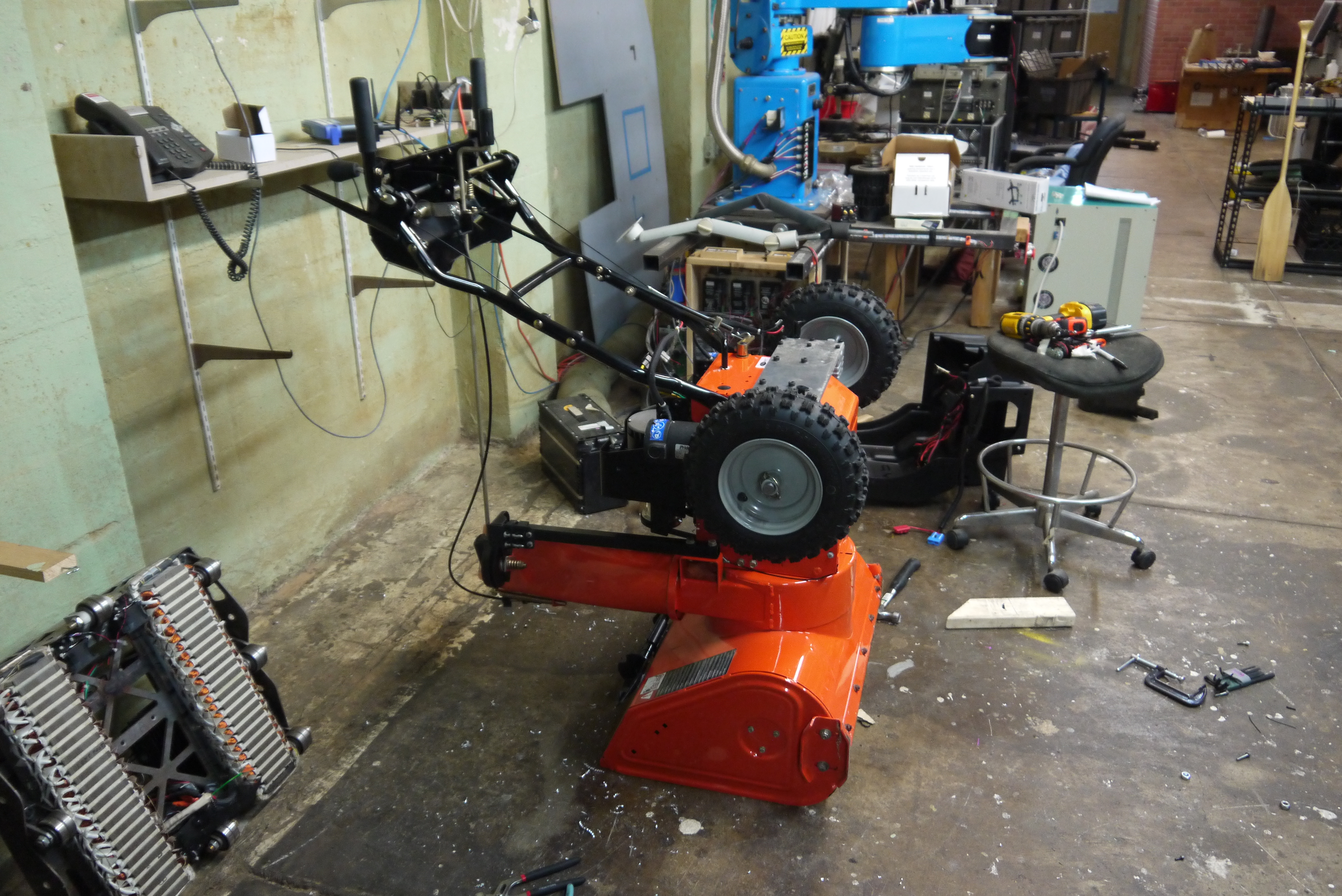
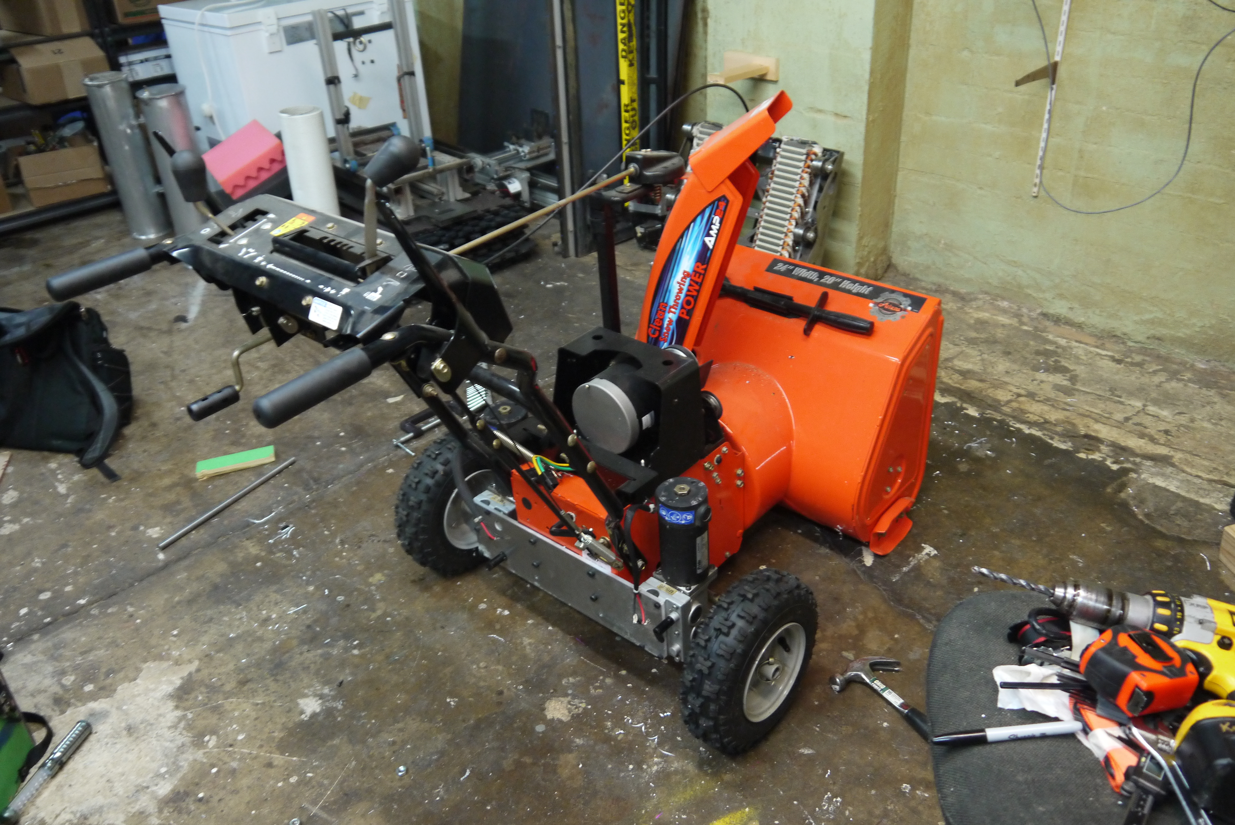
While it looked a bit absurd, it was taking shape. At this point it was 7PM and the storm was scheduled to appear by 4am. Time to get to work. Next up, remove all the handle-controls, make room for battery packs and set up some electronics. 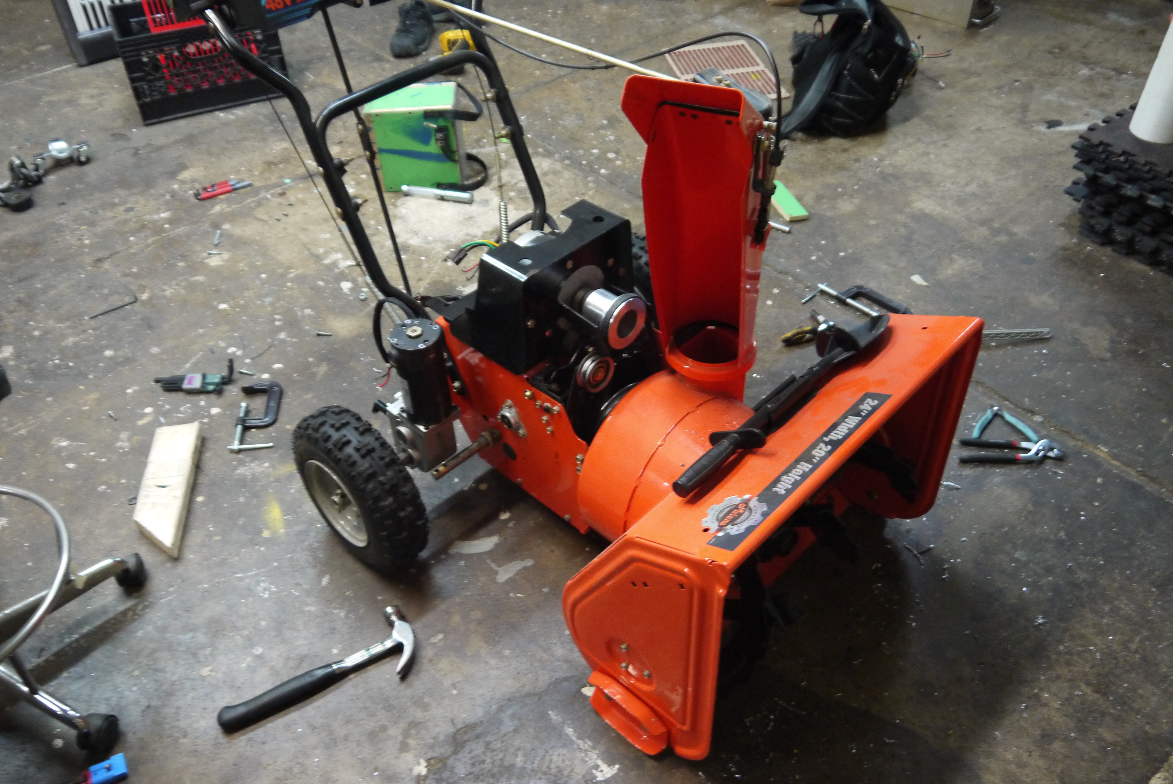
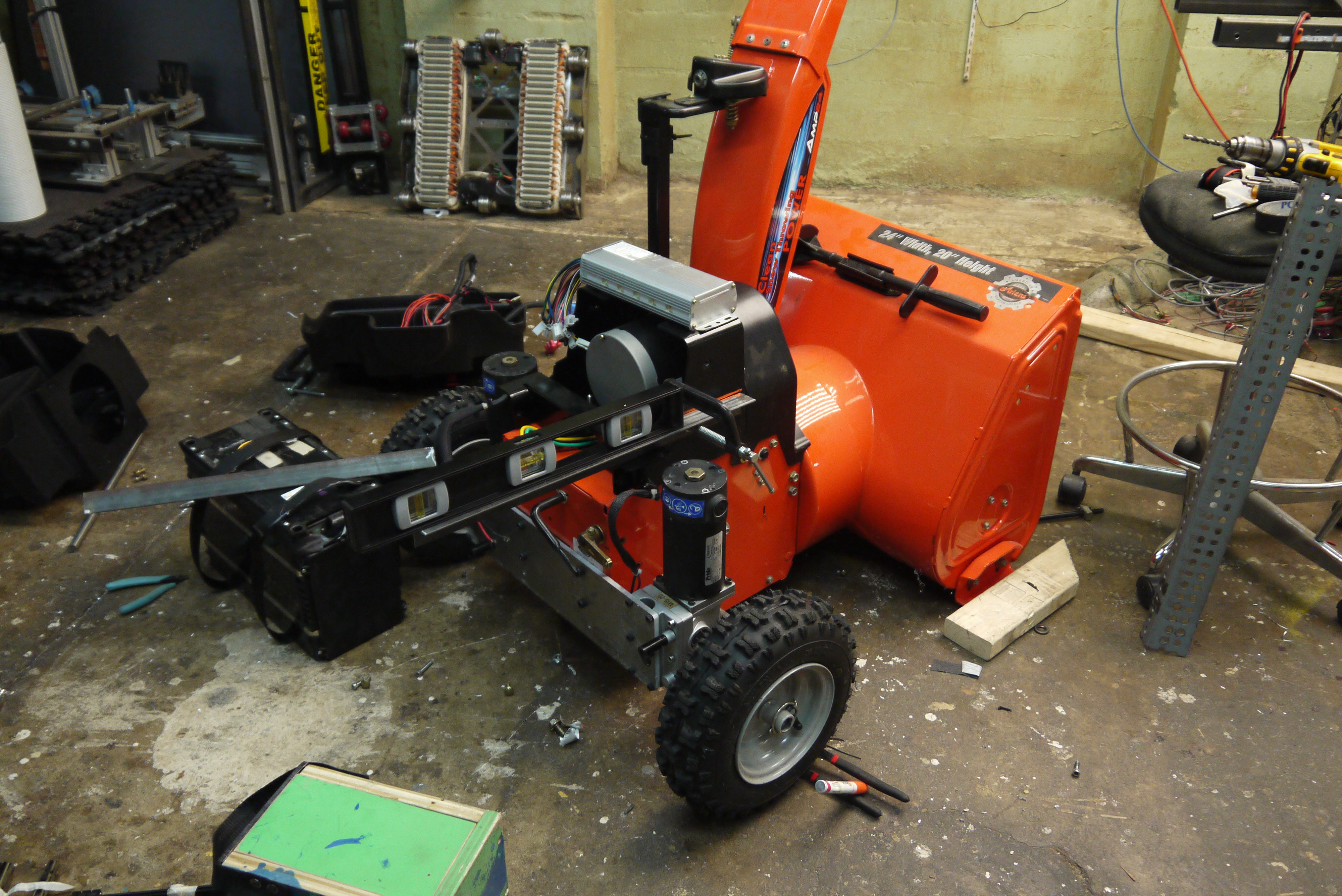
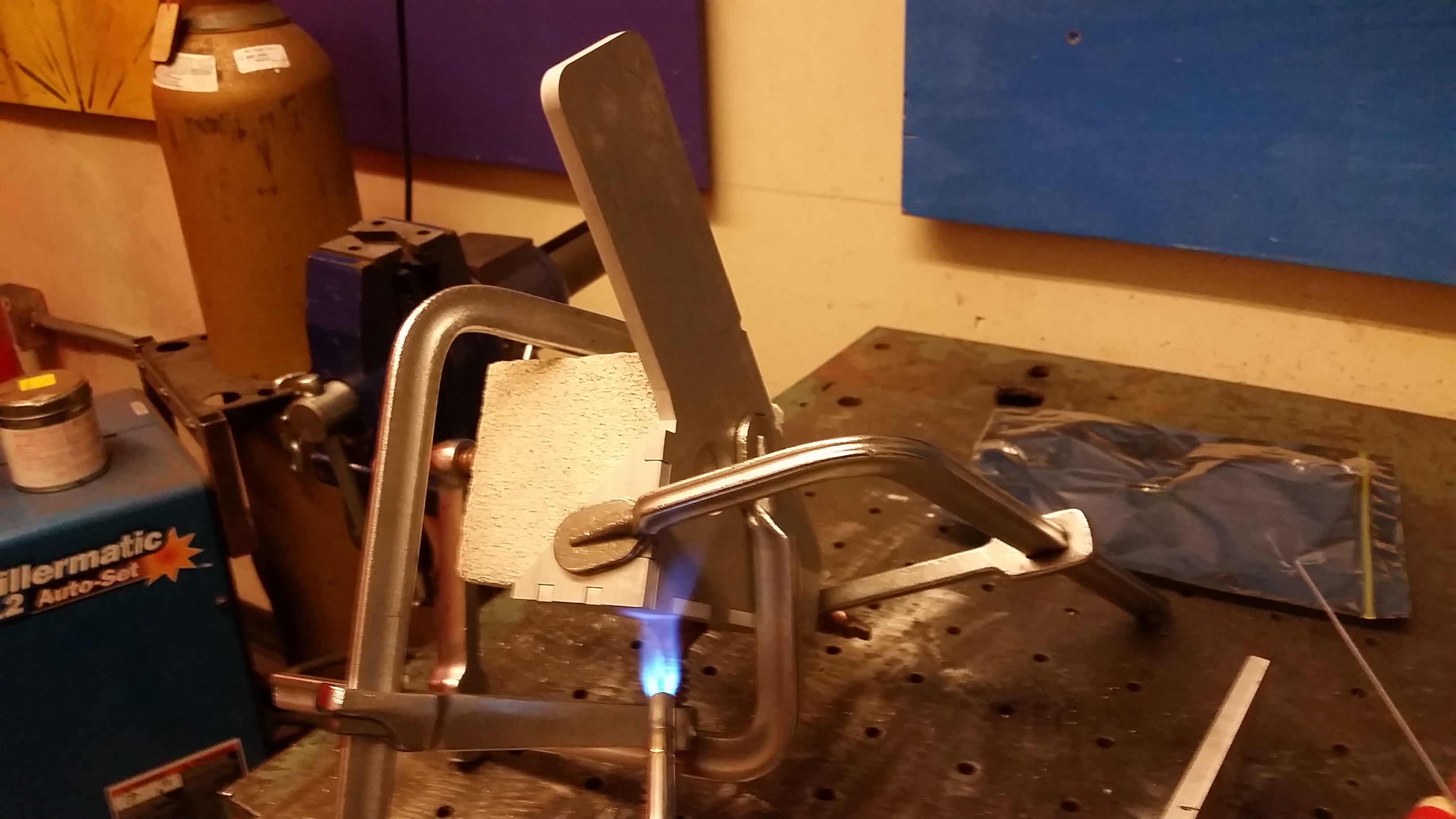
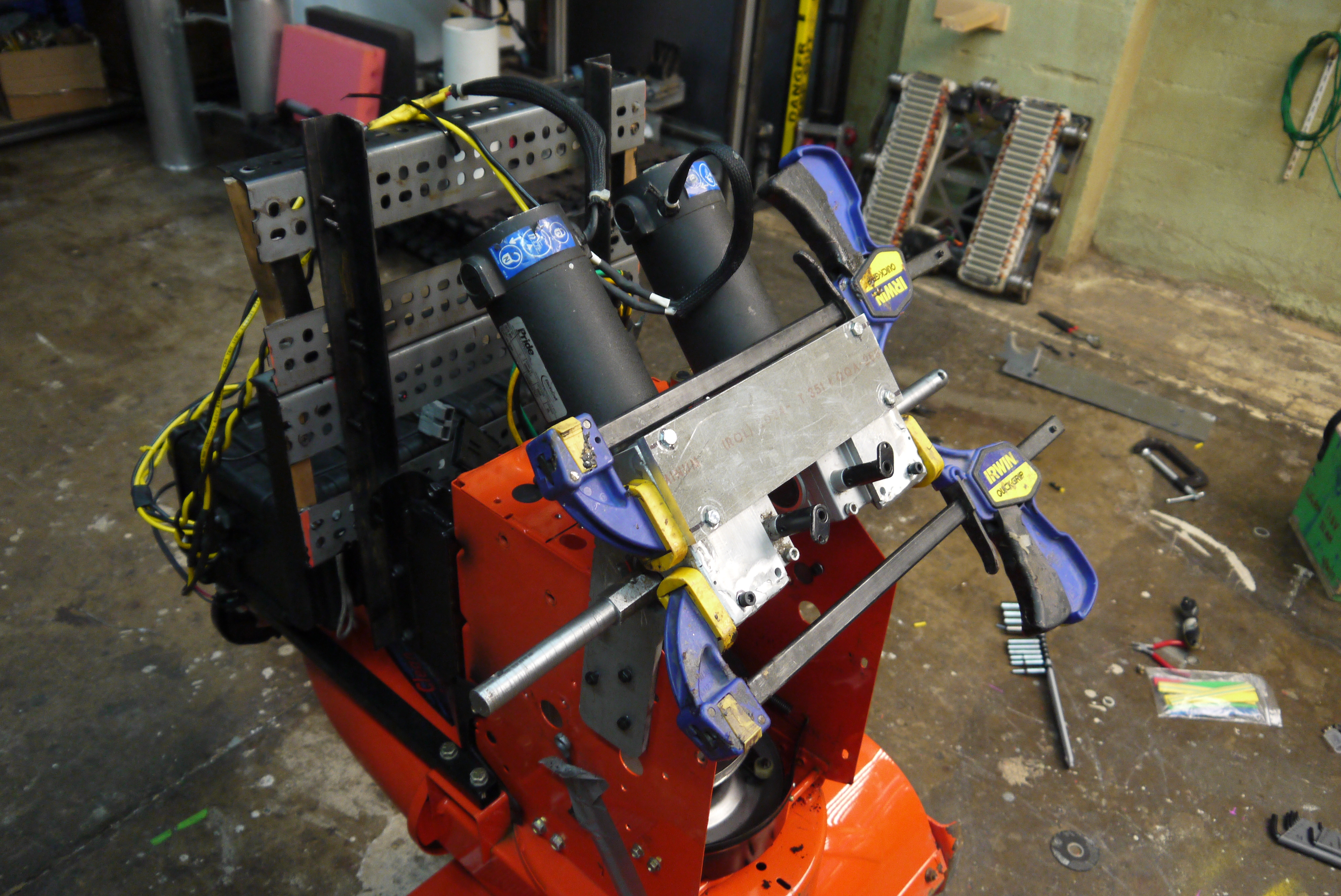
Using some angle steel, I attached directly to the motor mount baseplate. Each of these extends about 10" behind the rear of the snowblower. I used a magnet-mount level to make sure that the battery platform base would stay relatively parallel. 
C-Clamps were used to hold the angle brackets in place while pilot holes were drilled. I drilled through with an M8 Tap drill and then clearance drilled the angle bracket. After tapping the motor mount plate, I applied a locking compound to the threads and bolted everything in place. I found that leaving everything loose and slowly tightening, with an eye on the level, worked well. 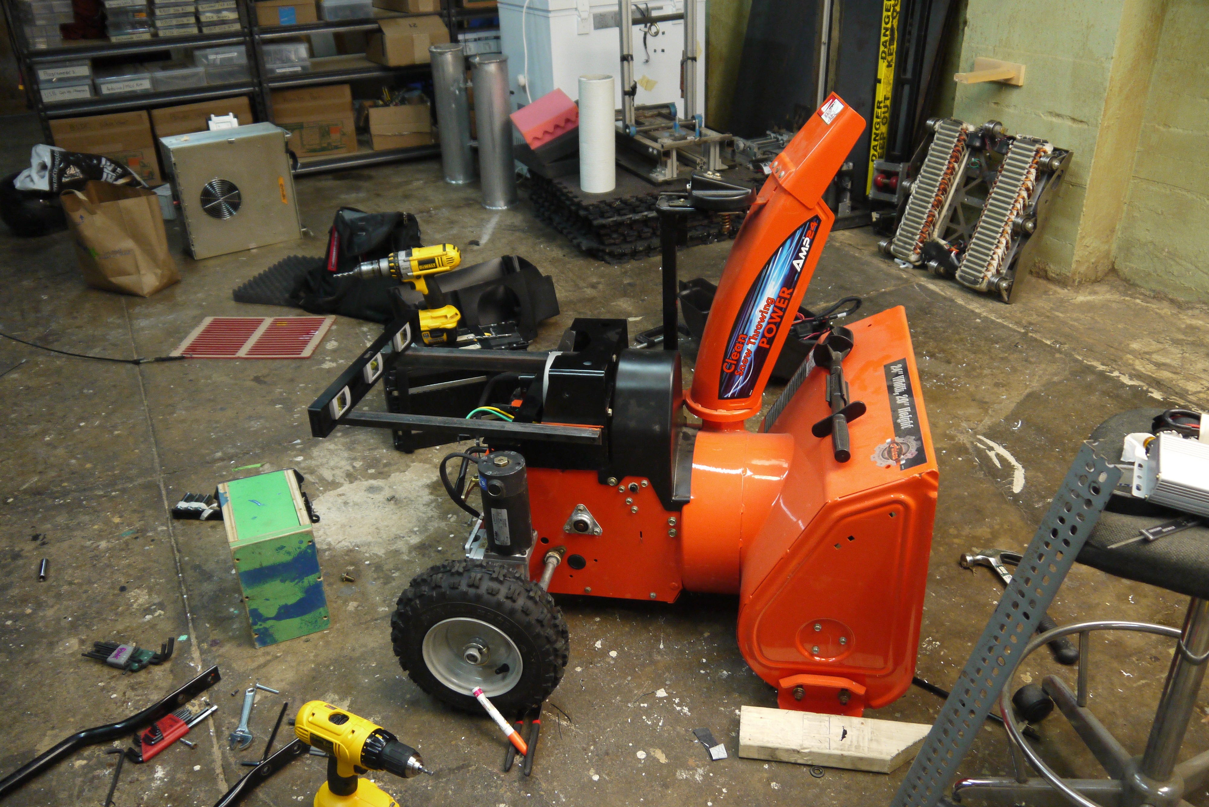
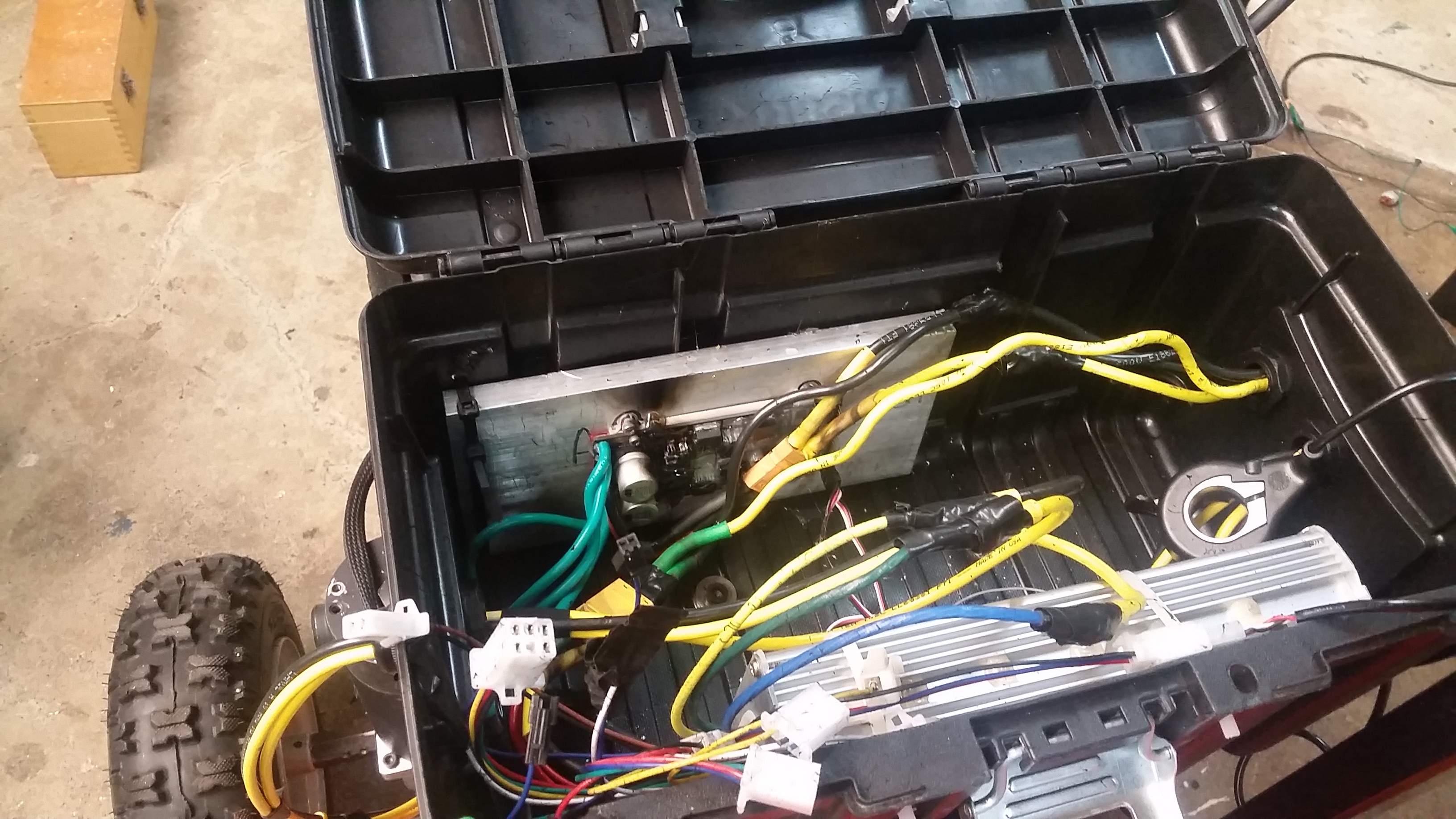
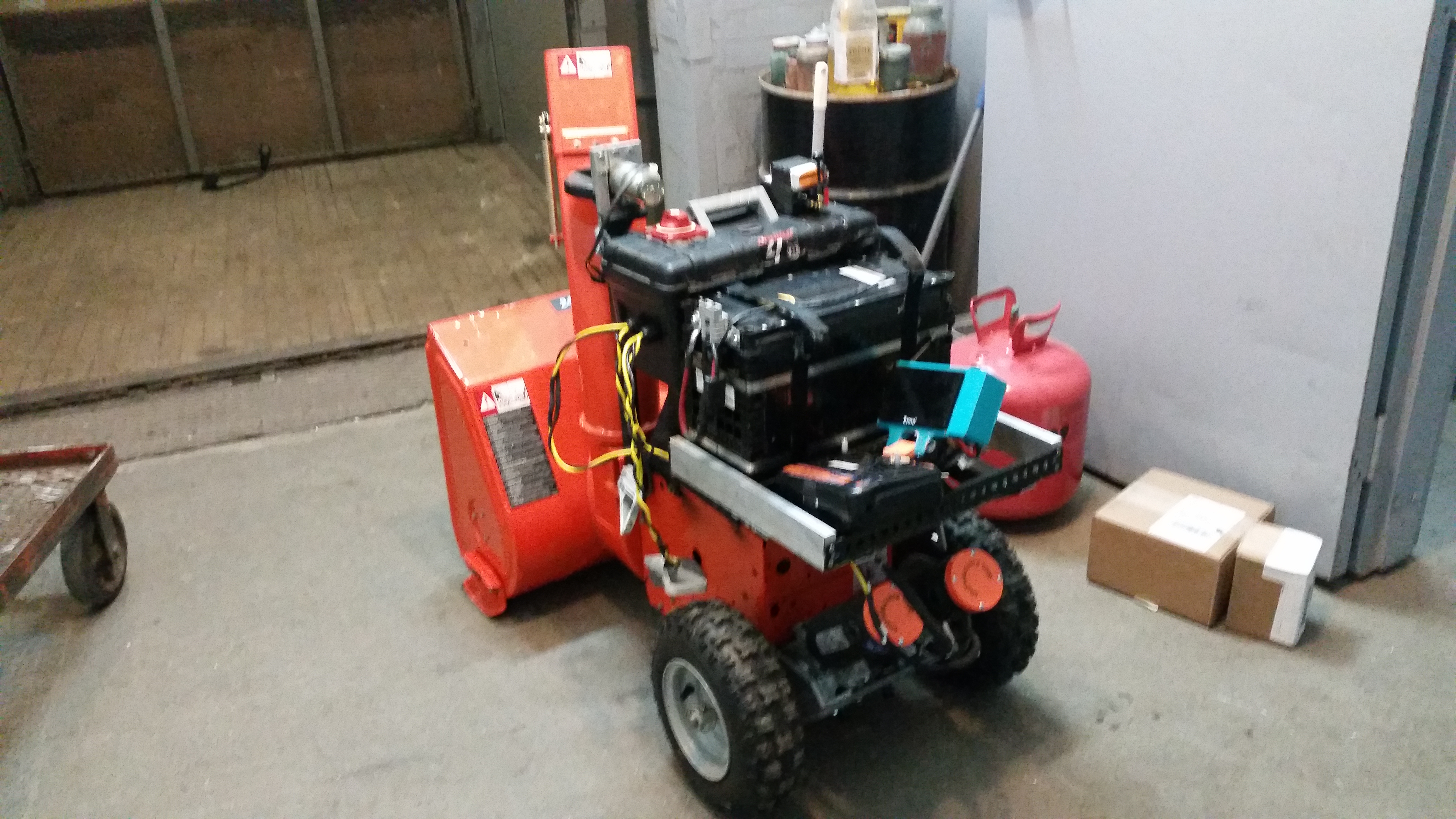
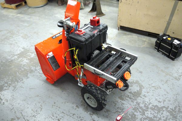
Next up, electronics containment and finishing the battery back. I will remind you that, ahem, the storm was upon us. I had a former Christmas present toolbox that had sat silent for over a year. It seemed quite excellent and rather waterproof, so, some fender-washers and bolts later... It became part of the snowblower. I was fortunate to have a few watertight cable-glands handy for running the motor cabling through. 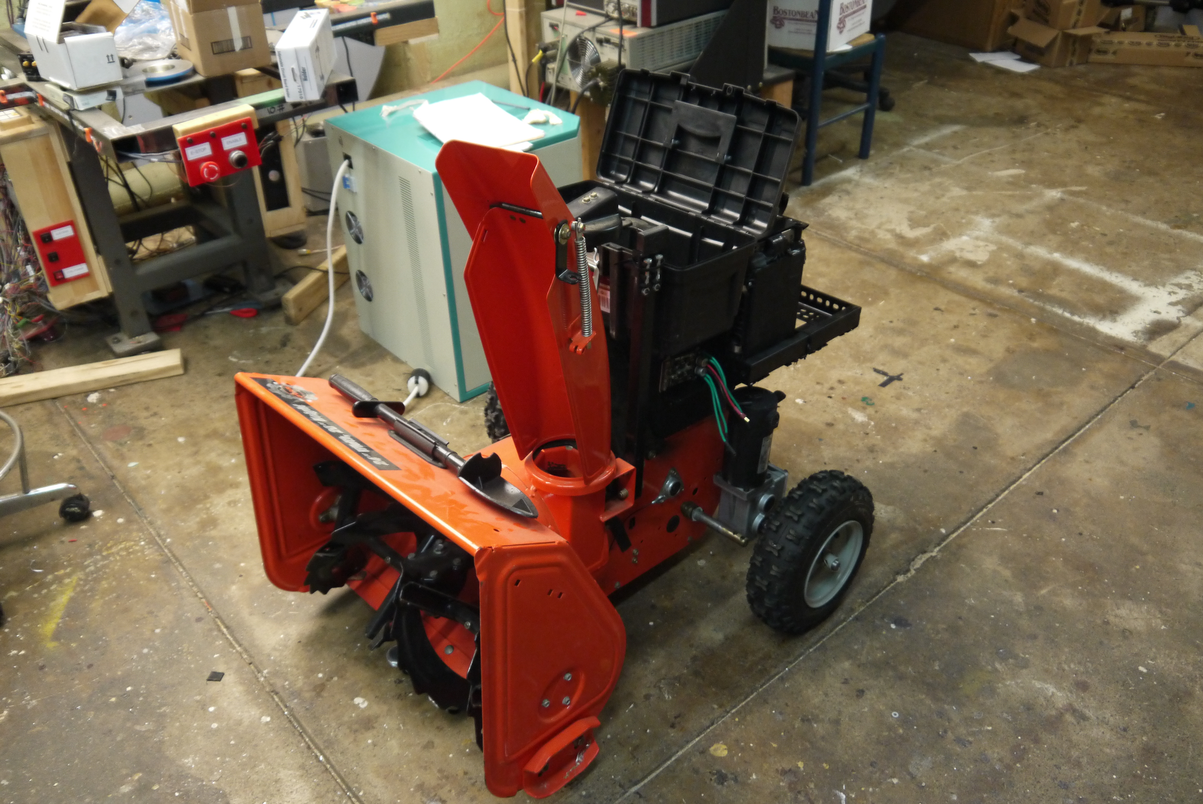
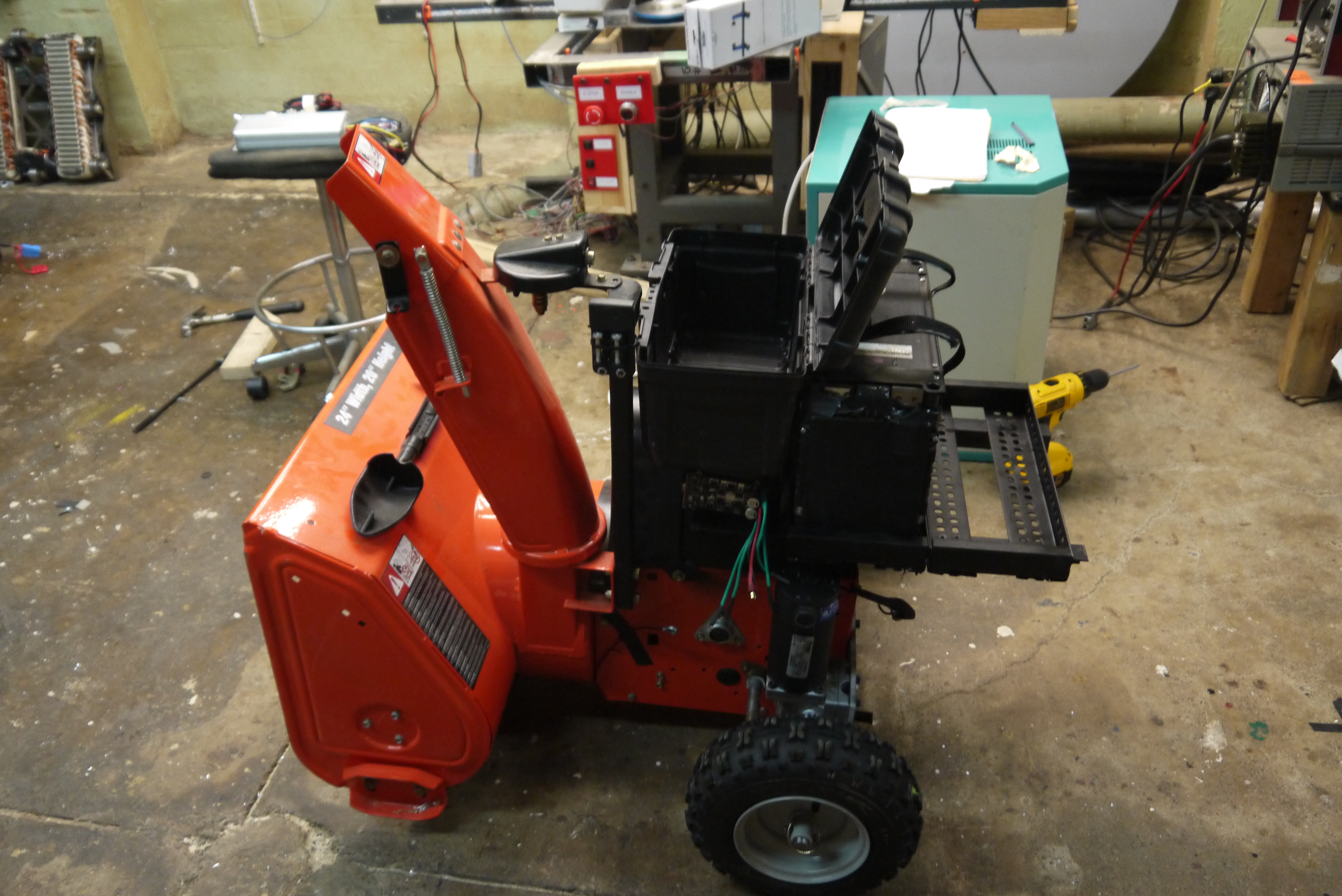
This worked quite well, a little oddly shaped but reasonable. Note the photo shown left is quite 'burney' more on that later. Two plates were attached as heat sinks, one to cool the three phase bldc controller and one to cool the drive motors. 8 awg wires were used to run the high current applications (two dc-brush motors and three phase impeller). 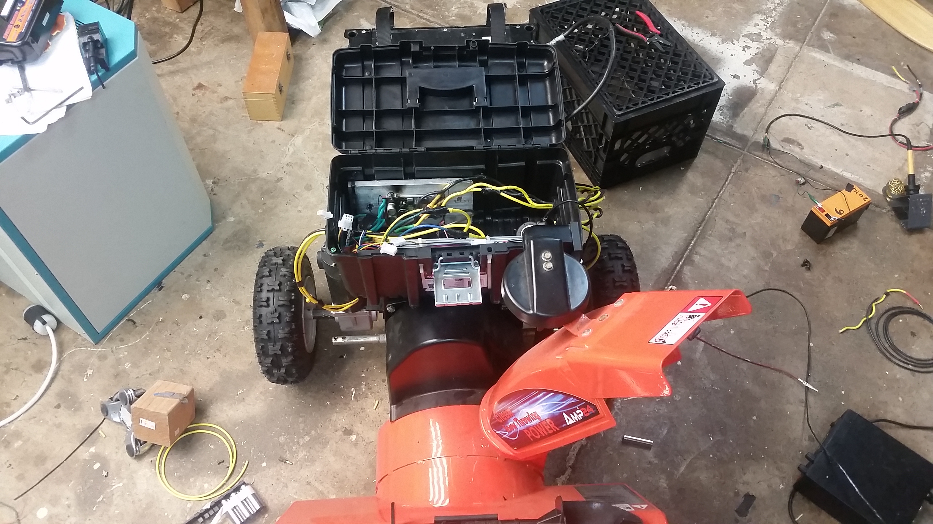
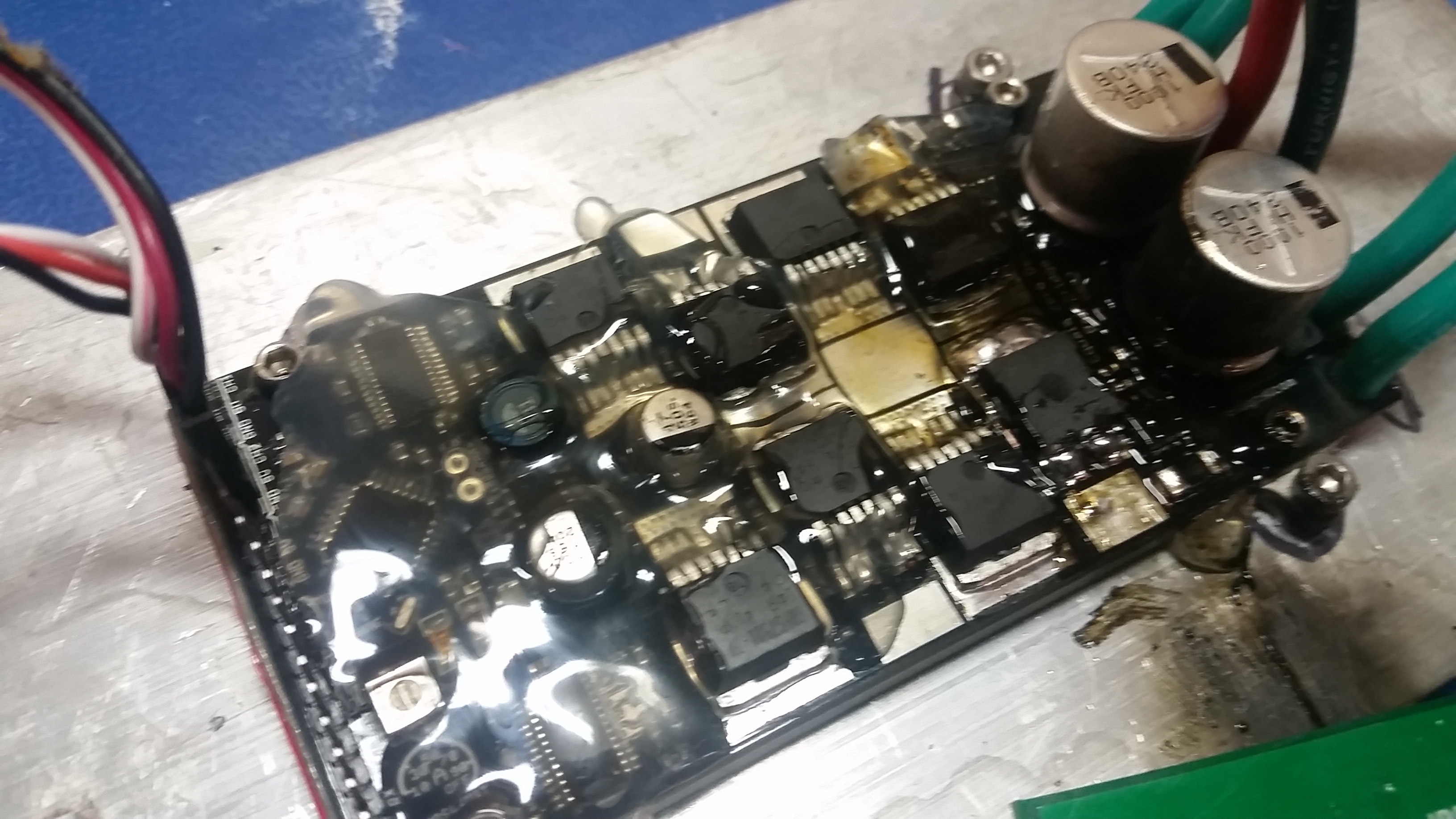
For the motor controls i had co-opted a ragebridge v2, formerly from the battlebot HaluCination. To prevent snow-intrusion, holtmelt adhesive was used to cover the board. Heat-sinking to a larger aluminum plate was provided to ensure the drive electronics stayed cool. Nominally the ragebridge is rated for 8S LiFe operation, however it quite effectively grenade-ed itself. It appears a gate-drive failed and left the low-side mosfet in the linear region. Nominally this was probably damaged in battlebot duty, so i gave it the benefit of the doubt. 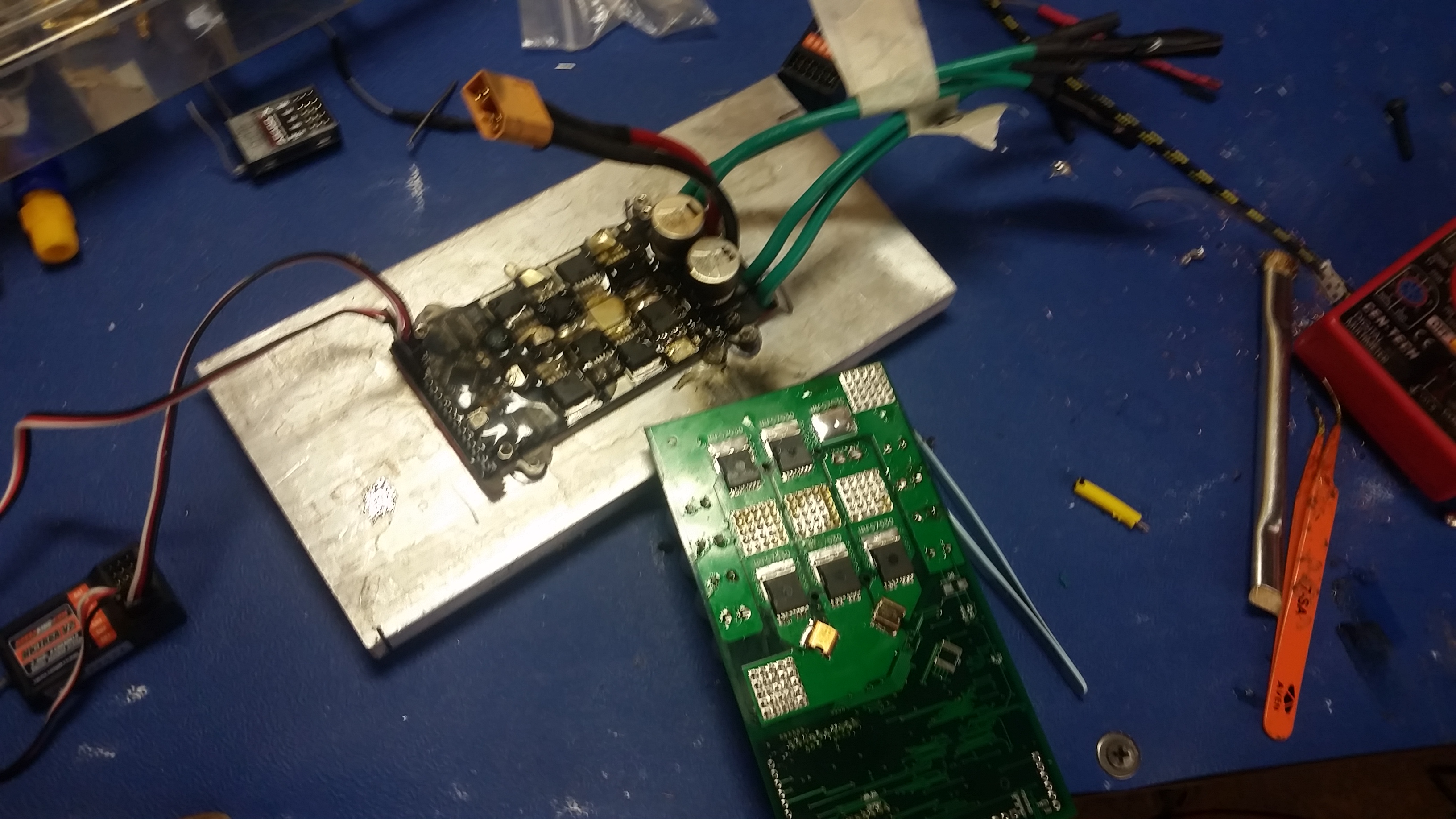
I fired up the UP! mini and made a case for a new ragebridge. An hour or so later it was mounted in place and I was back up and running. 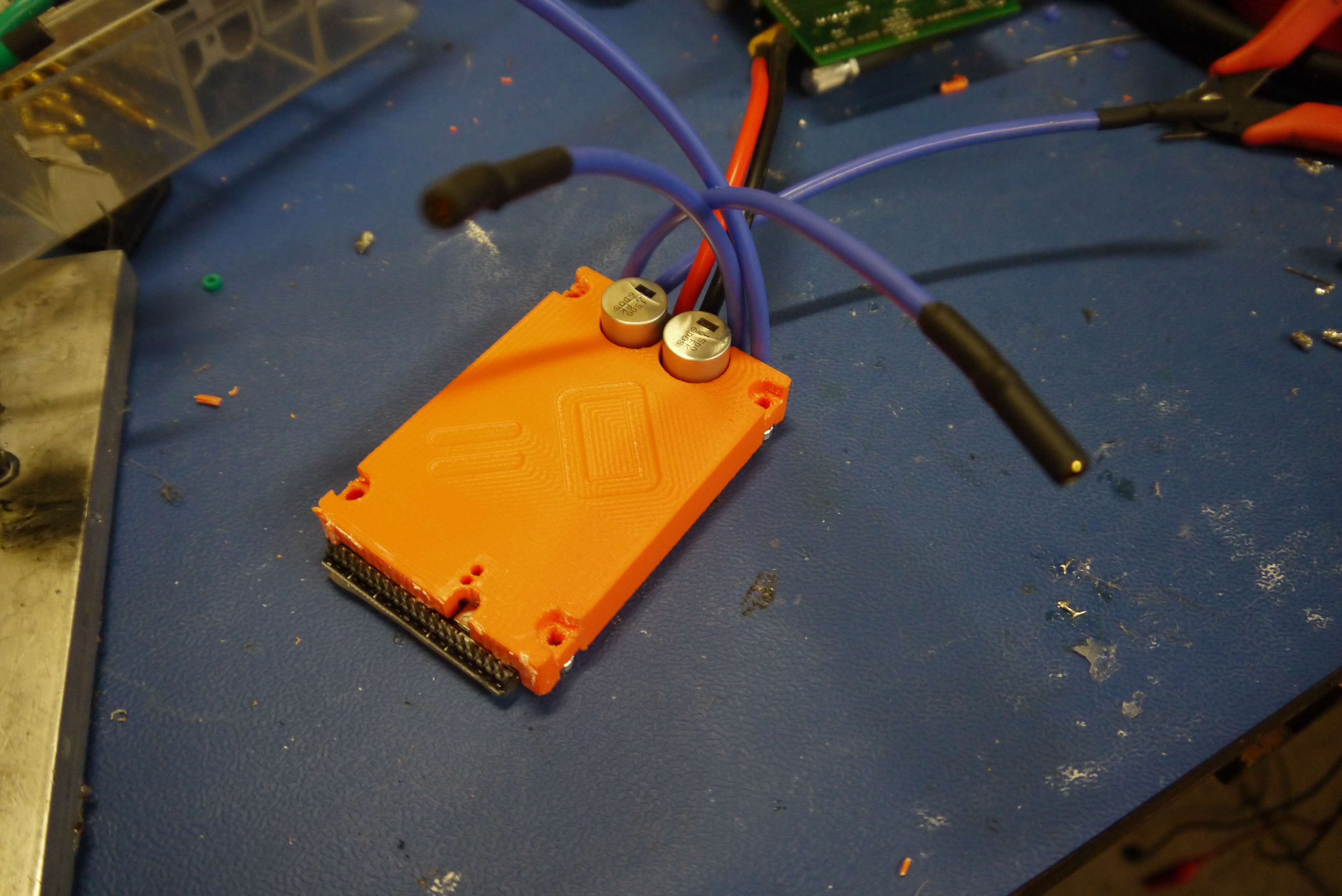
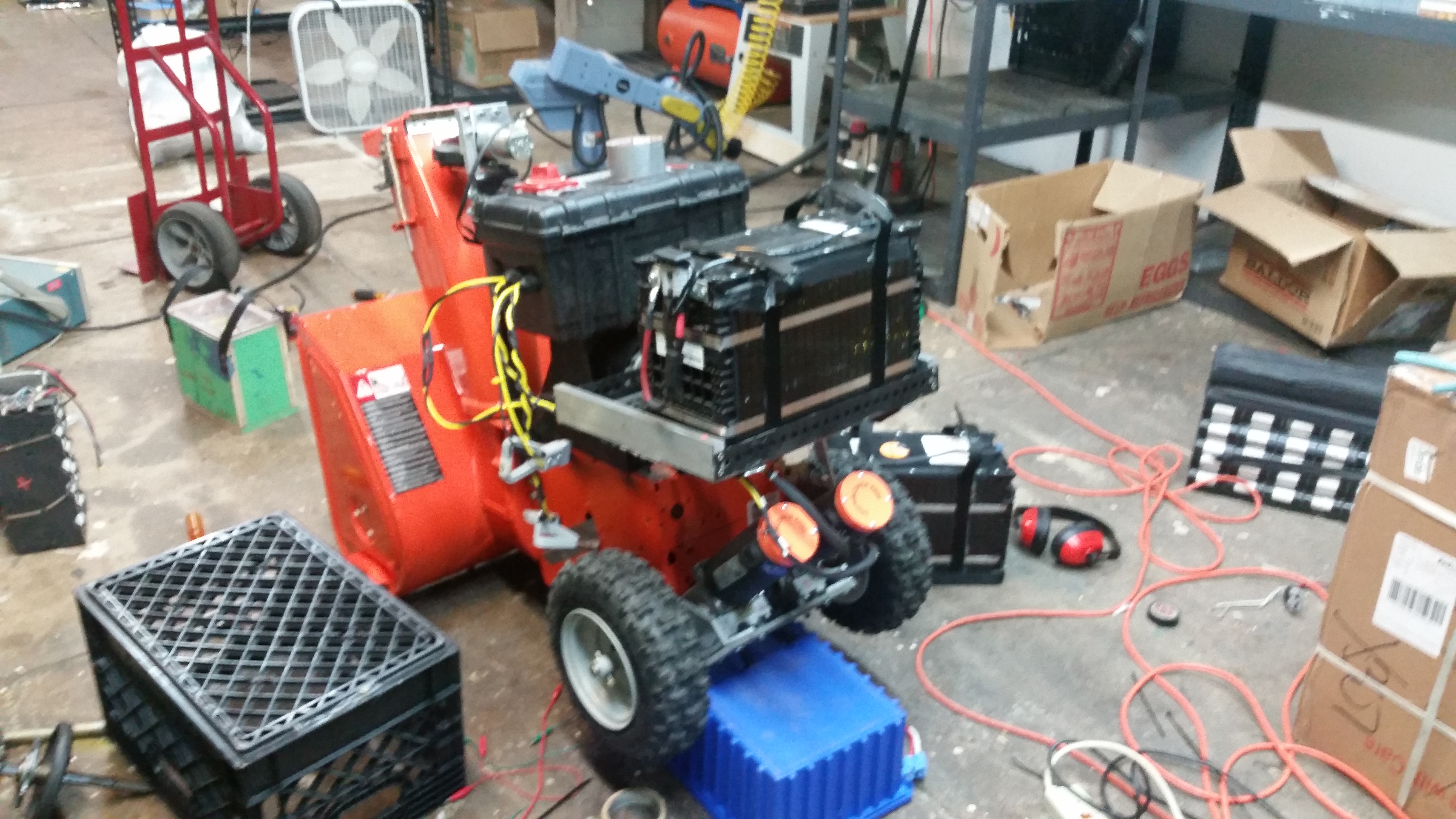
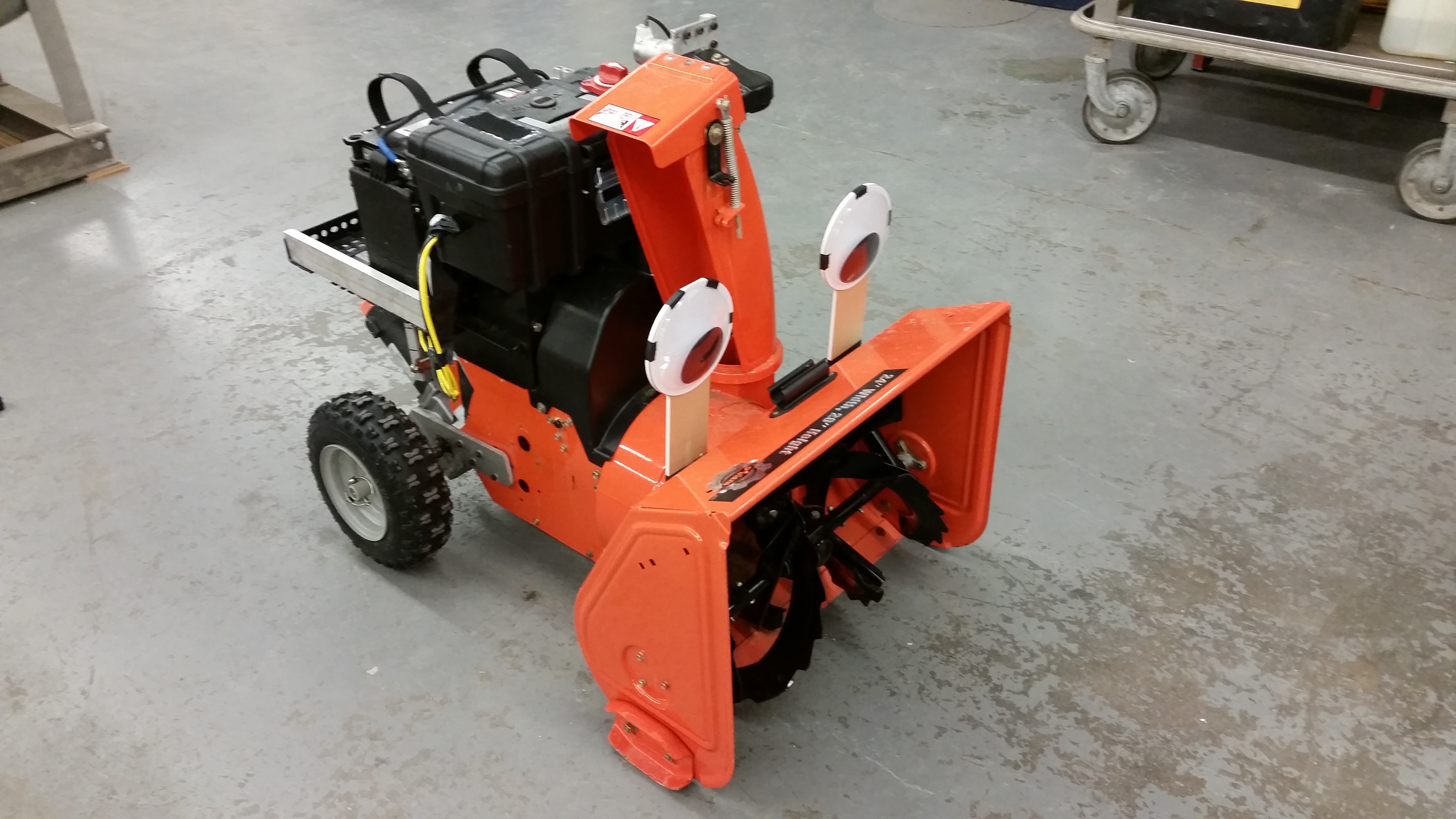
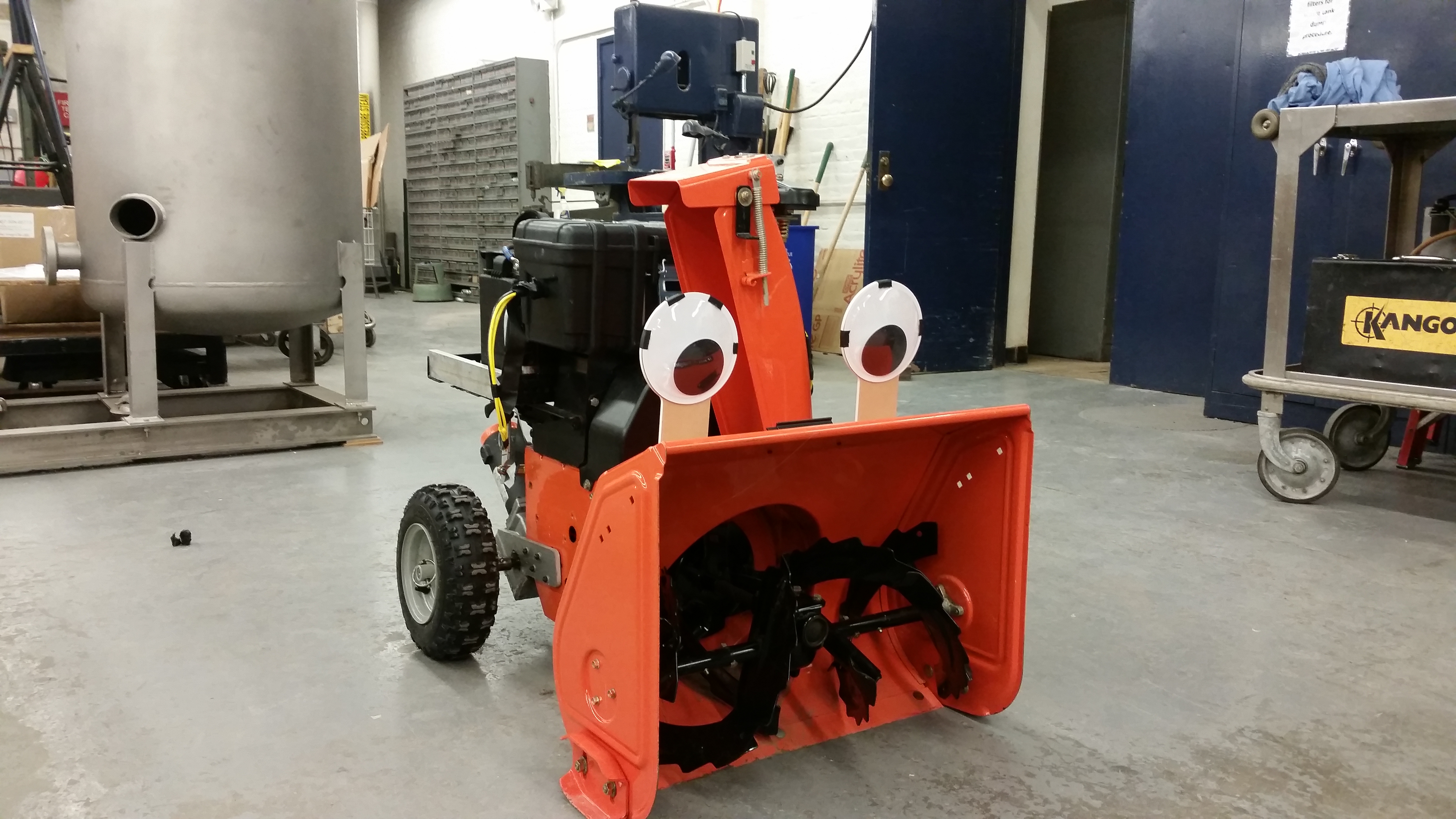
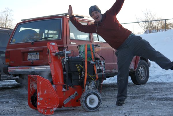
A Snow Creature EmergesAt this point the great snow creature began to come to life Apologies for the mess in the background. At this point drive and chute were complete, and control of the impeller was the only outstanding item to sort. For this test i was running everything from a single 4S LiFe battery (13.6v nominal). I hadn't completed connectorizing the battery packs, and this was easier for a first-run test. Its impresivley lively at 13.6v, I was a bit anxious about running at 28v. Just seeing it jumping about really provided some extra incentive to get everything done. The great bomb-cyclone was approaching in ~4 hrs at this point. Giant Battery Pack ModulesThe battery packs for the electric snowblower were scrapped from a prototype battery backup for cell phone towers. Each module is an 8S 6P prismatic A123 LiFePO4 module, or 26v 120AH. The two modules are connected in series to come in at 52V nominal (6.2kwh total). I know what you're thnking, "But Dane, I do not have giant prototype Iron Phosphate Batteries!" I understand, there are alternatives, Cells from a Nissan Leaf (40ah, 7.2v each) are readily available from surplus sources and a reasonable voltage pack could be assembled from 7 cells in series, less capacity but still quite reasonable. For a more straightforward approach, Four large PbAcid 12v tractor batteries could be used. 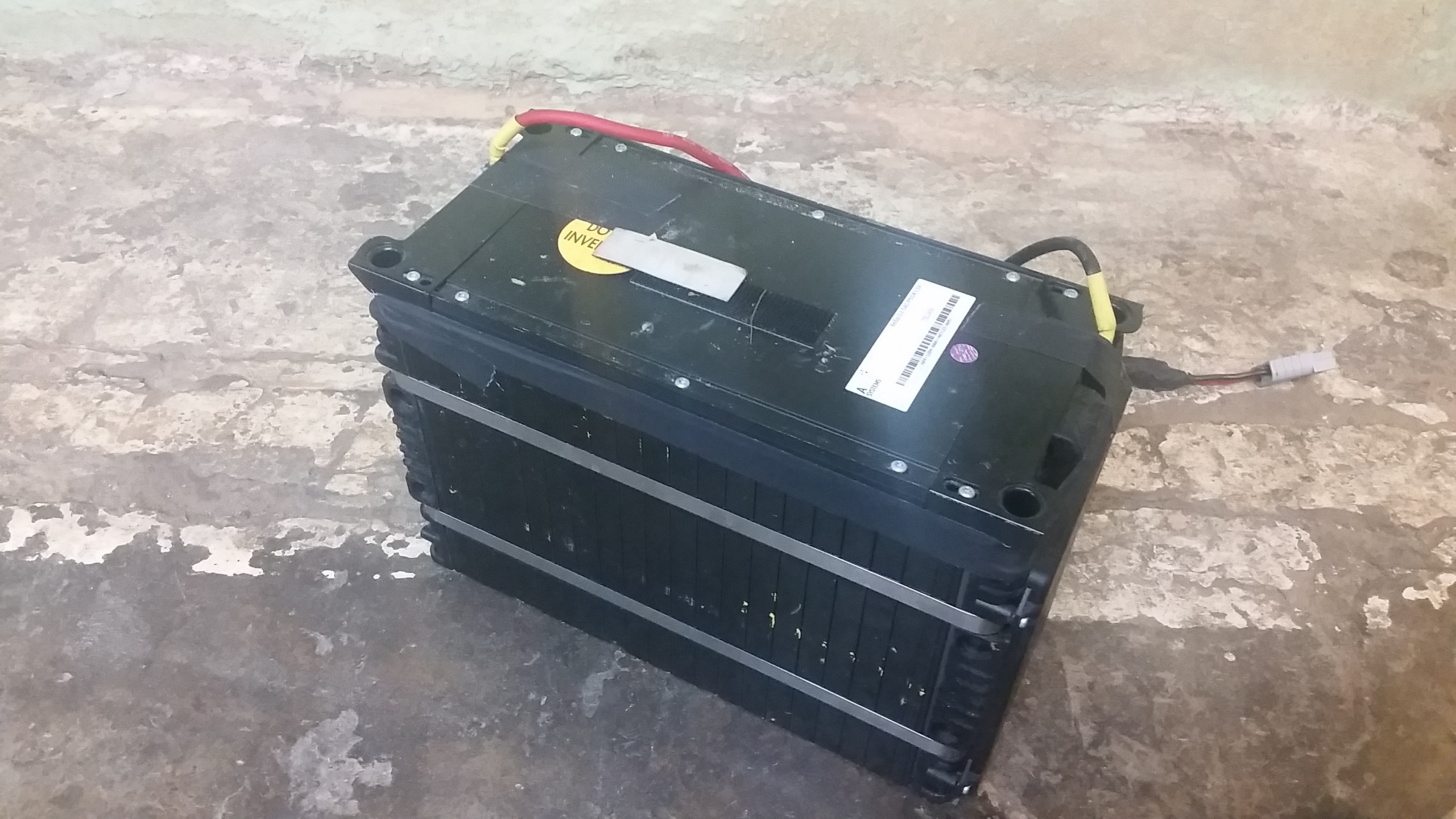
These were 'prototype' batteries, (unfortunately ones assembled during the open-loop-quality control A123 Michigan. T days). A cell group had died :/ Its very very difficult to 'cut them out and replace individual cells', as this involves un-doing the pressure-straps (the prismatic cells are always under pressure) grinding off the weldments, etc. So, I ensured the cell group was in fact at zero volts and soldered in a jumper. This pack was then re-labeled to indicate that is was now (7S) instead of (8S). 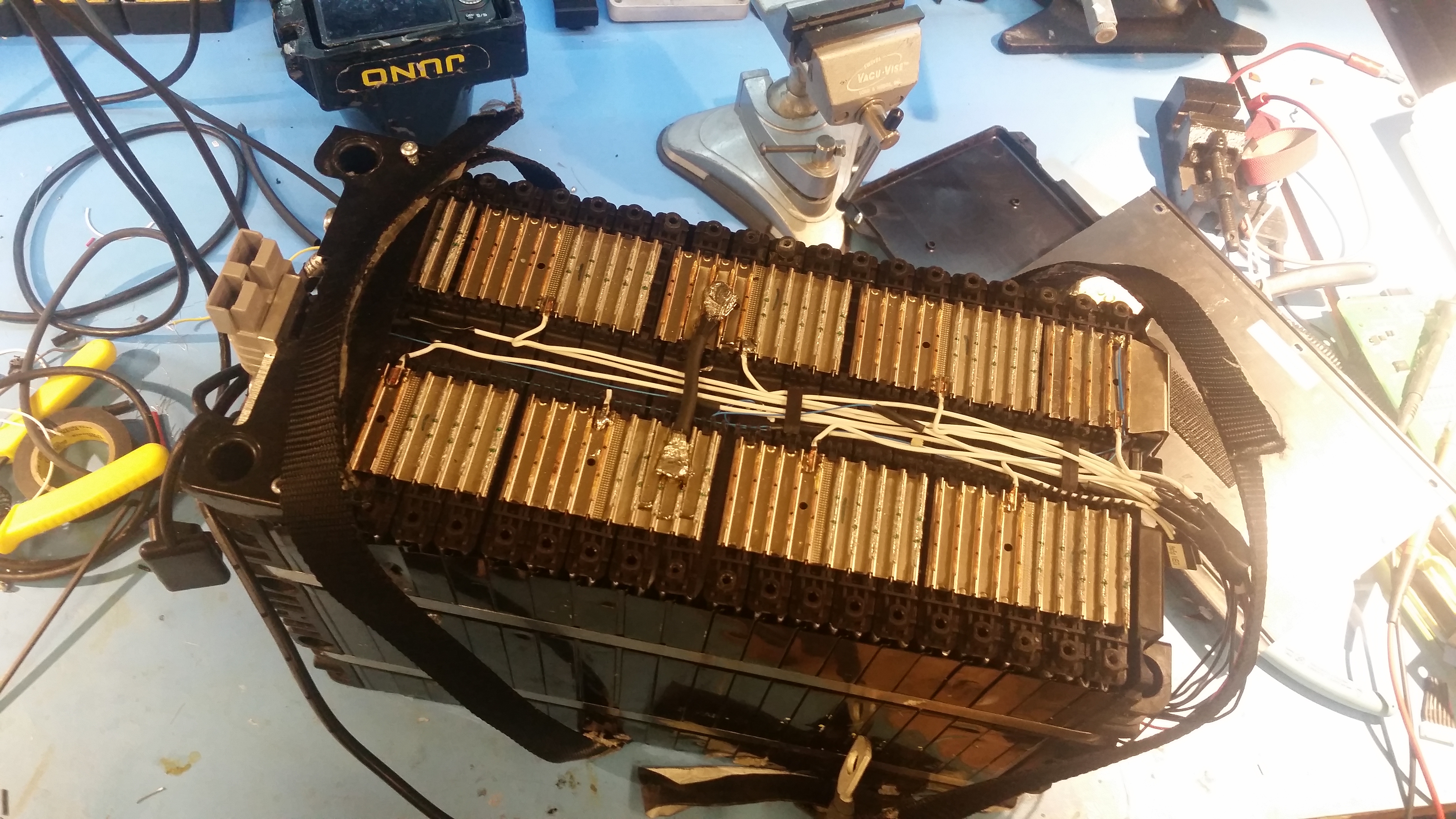
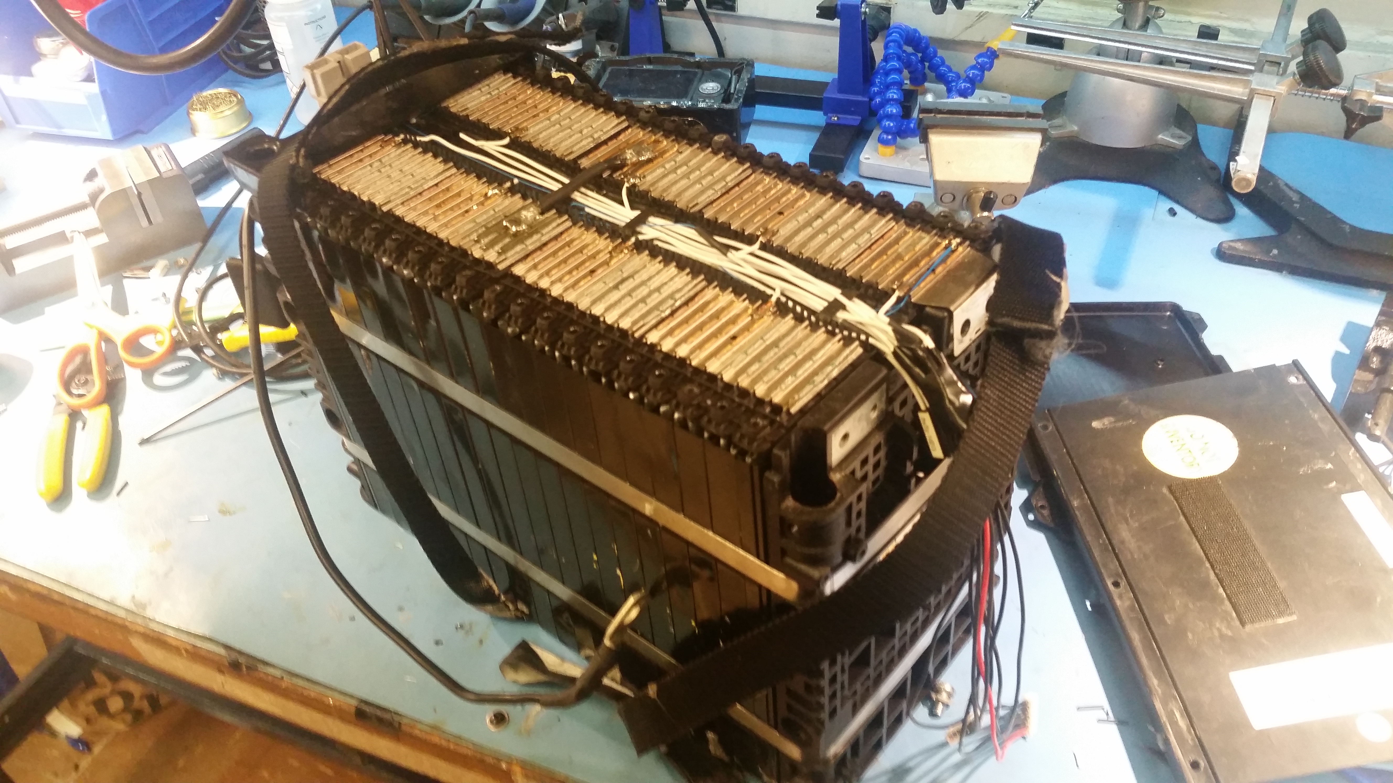
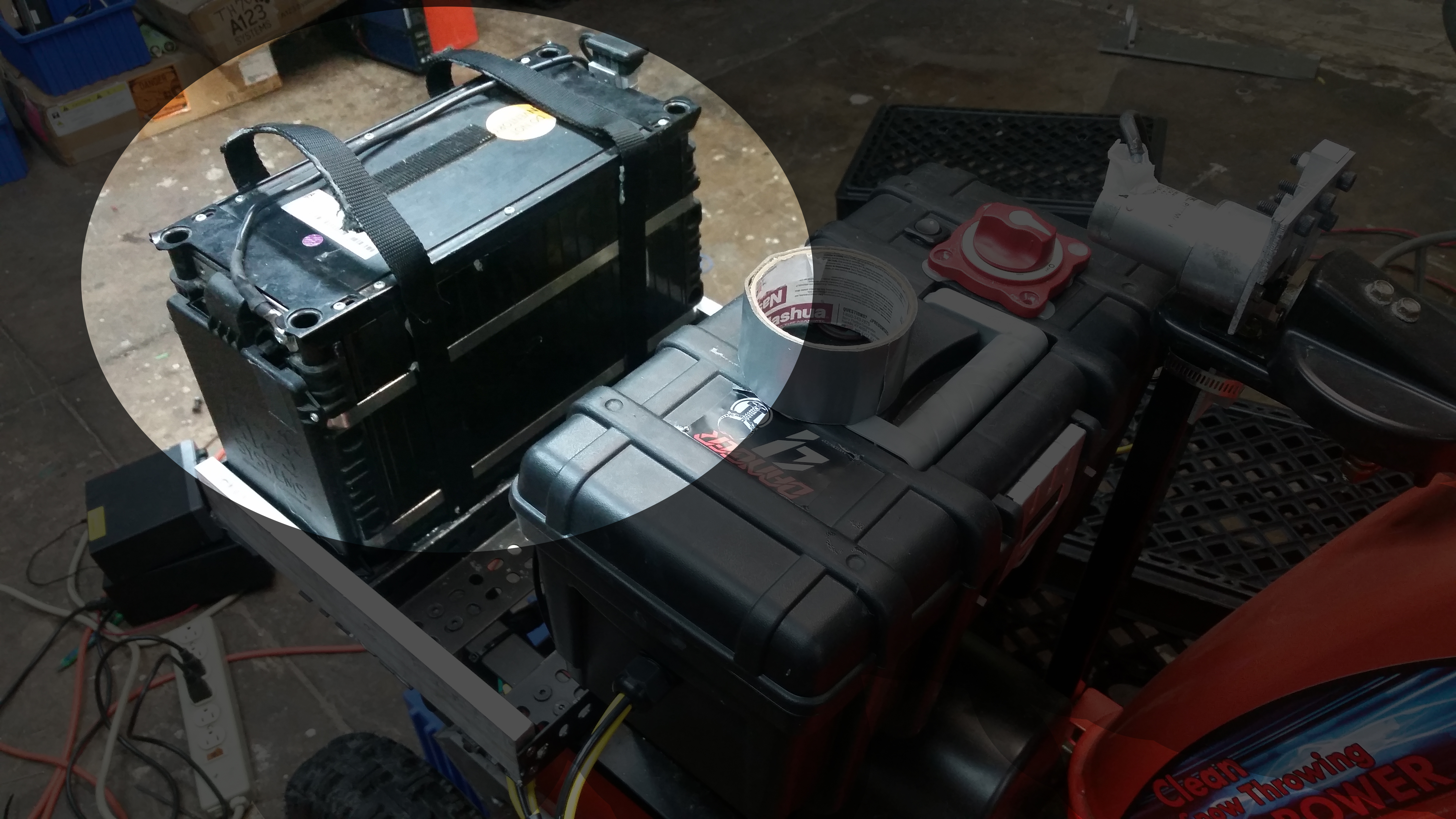
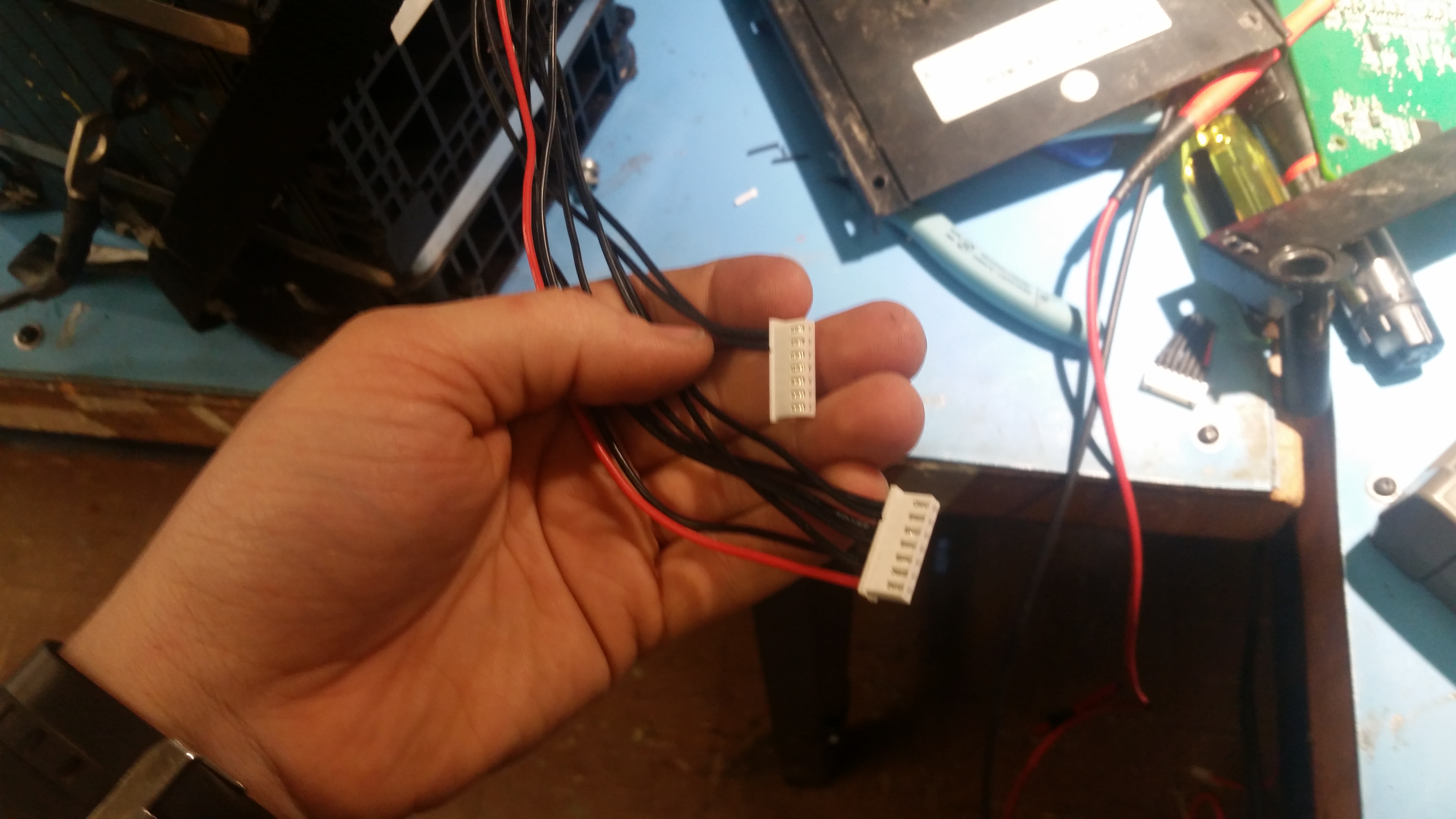
Balance leads were added to ensure that everything was matched and charged correctly. I ended up leaving these tucked away inside the side-pouch that contained the stock BMS. As these modules are on the heavy side (42lbs each) I added nylon webbing straps to wrap around and form a cute pouch case. I used a silione glue on the end of the leads to help prevent it from abrading / shorting out. 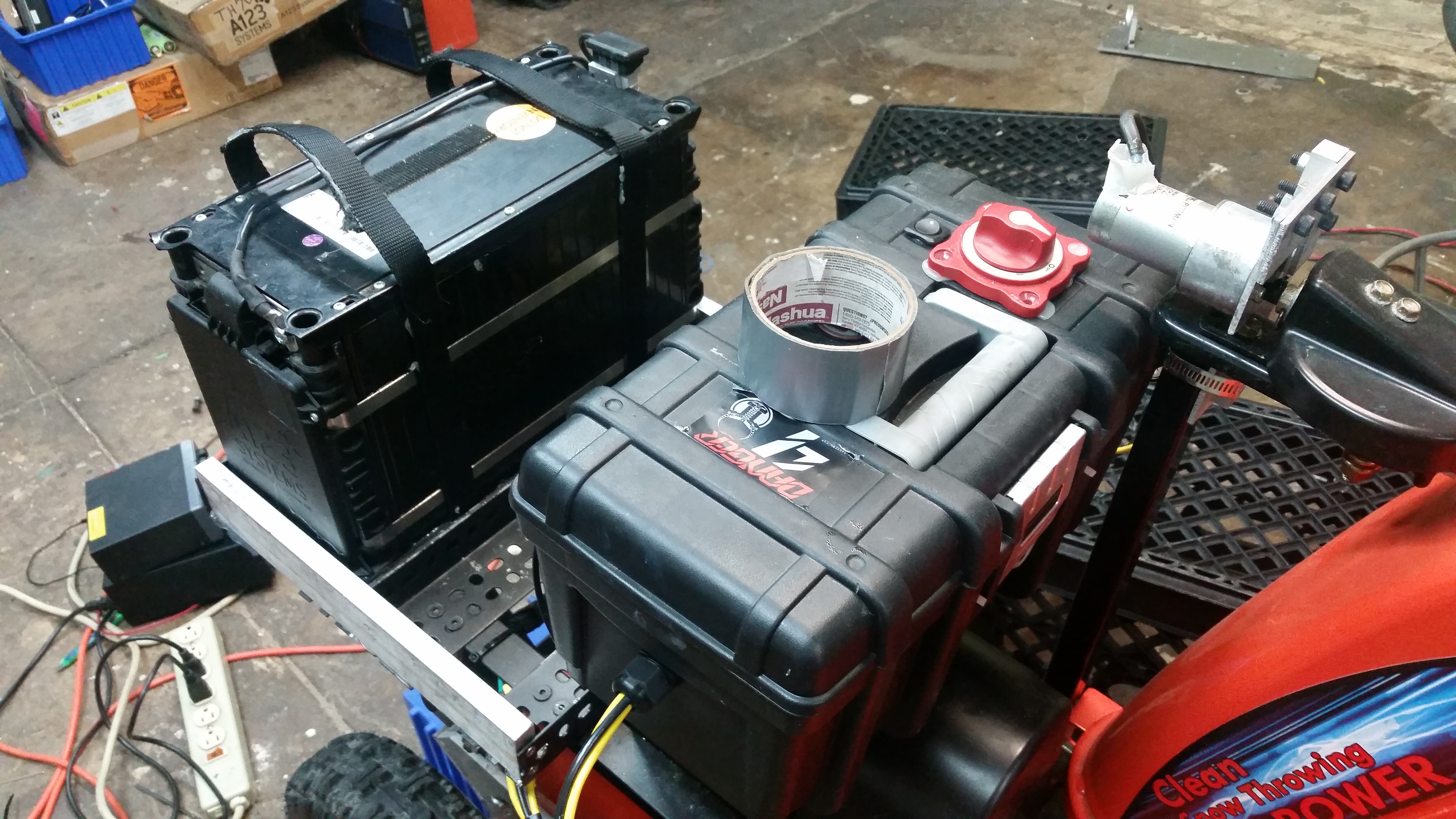
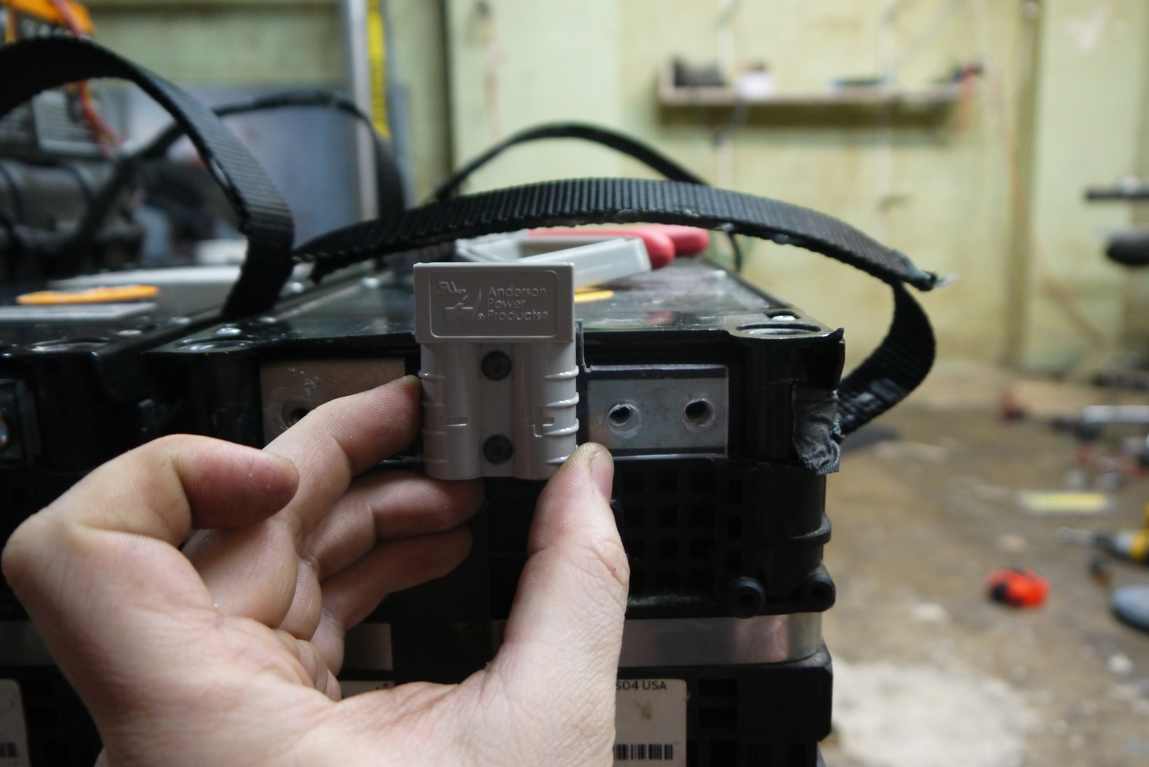
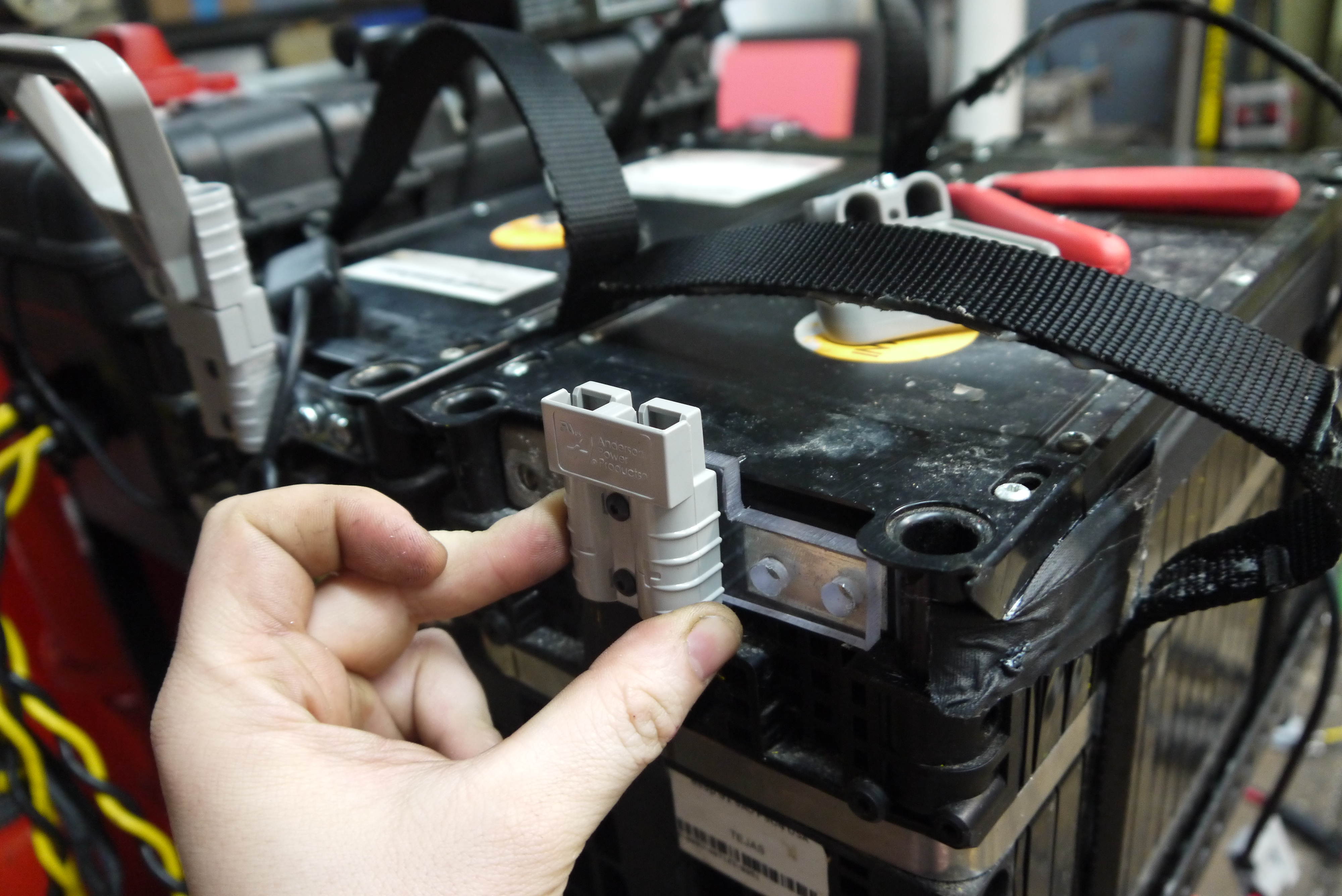
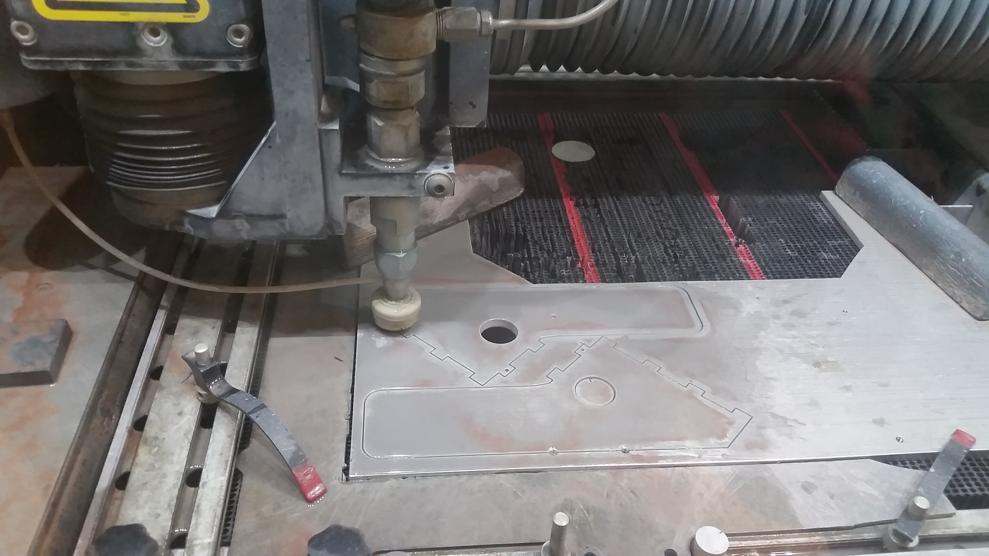
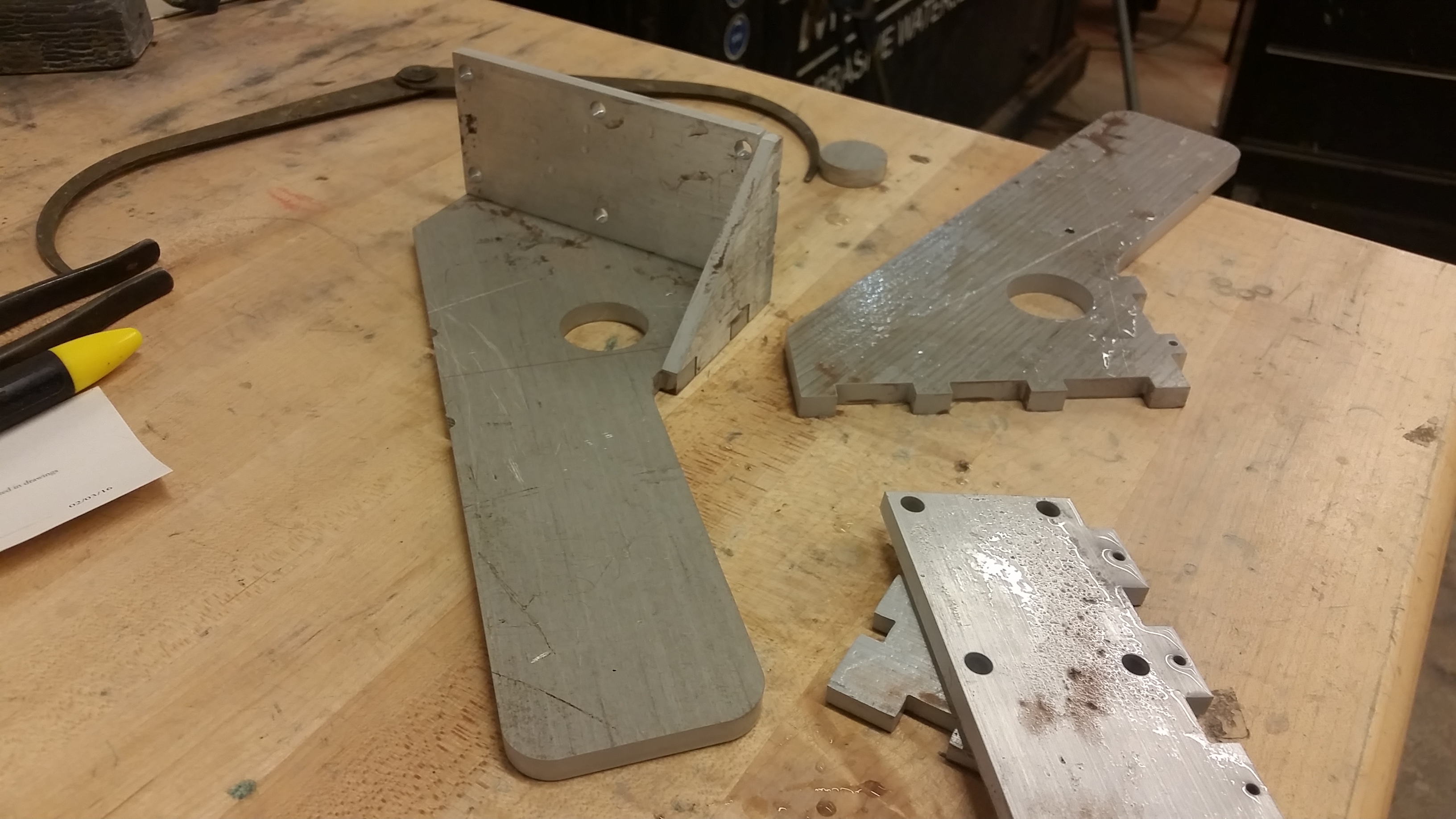
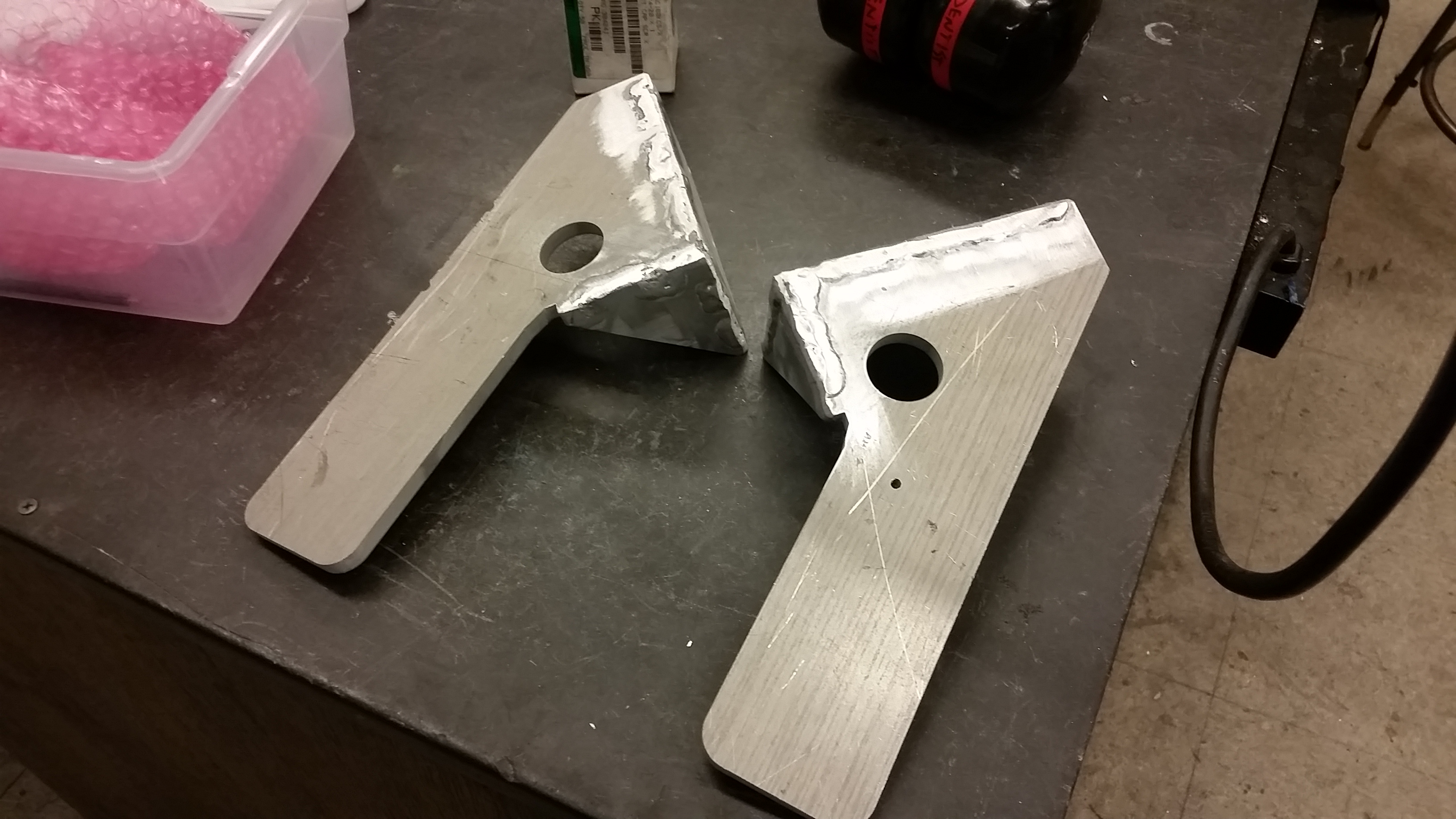
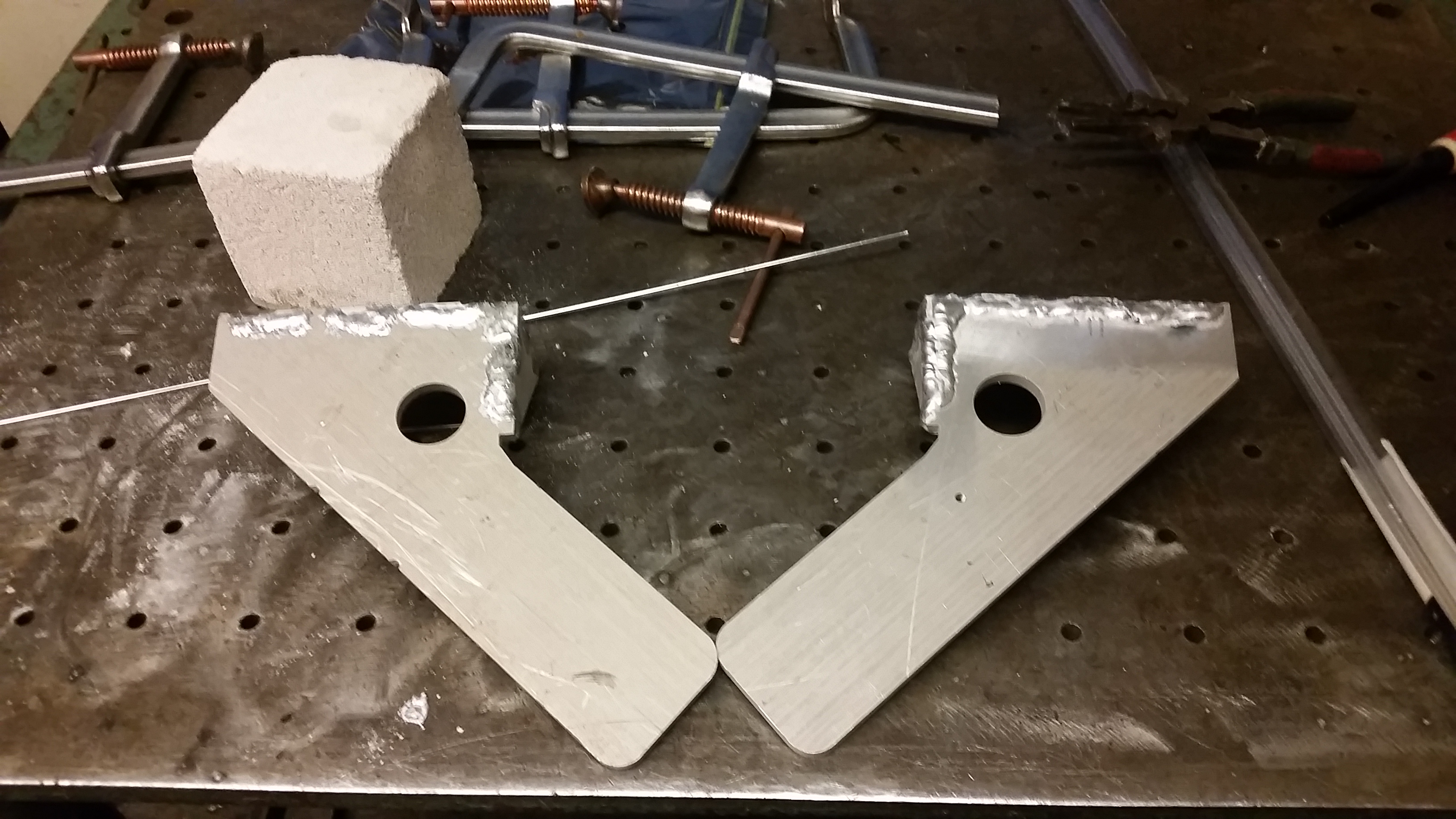
Next up was connectorizing. I did not want to hard-wire the batteries in place as, nominally, moving the batteries was waaaay easier than moving the snowblower. I opted for SB50 connectors and in-line 100A fuses located on the battery modules proper. Here was my thought, there's a non-connected metal post in each pack, make a small cut-out that holds the SB50 in place mechanically and then run heavy wires to fit. Some quick handsaw work later and lo, and adapter plate. 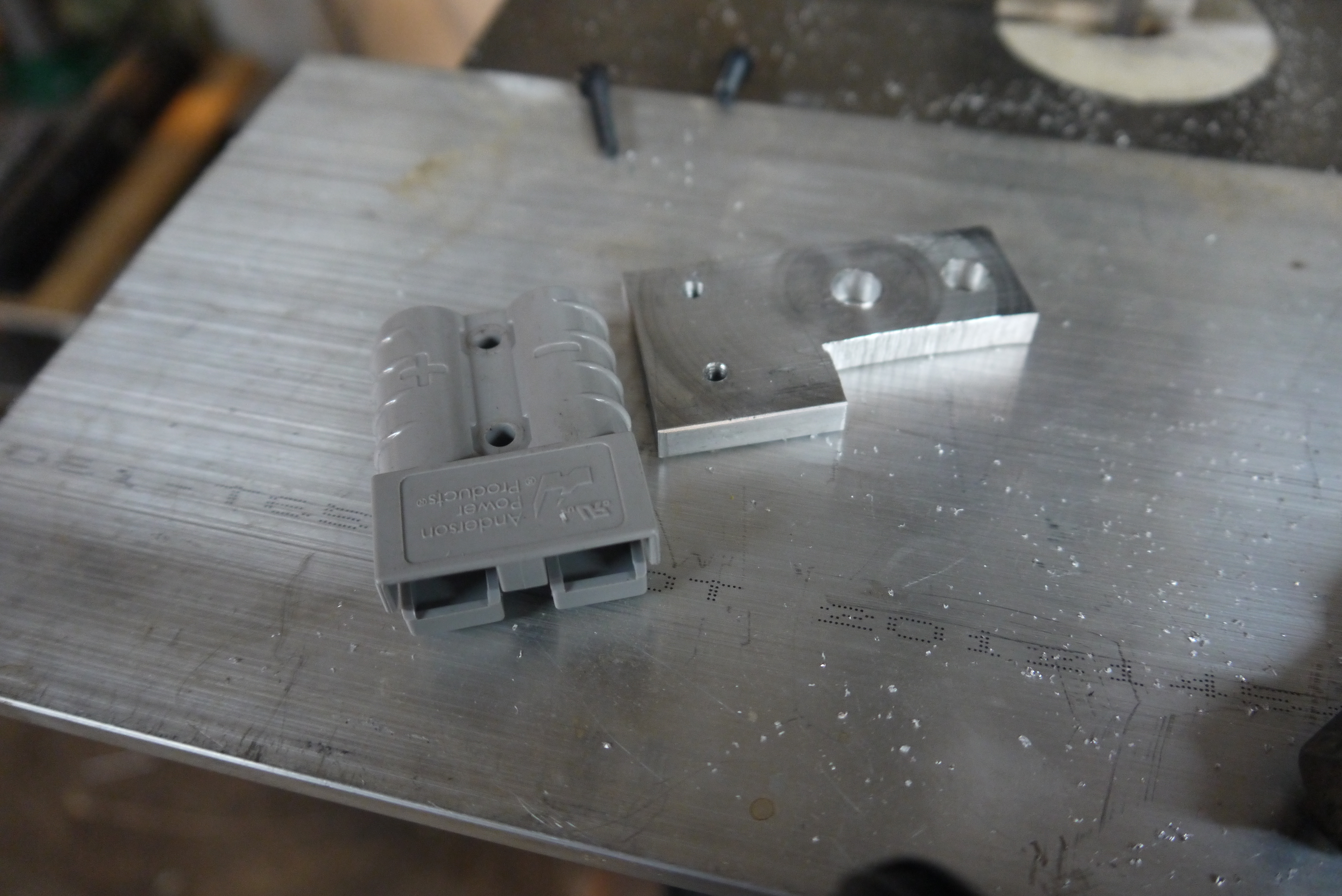
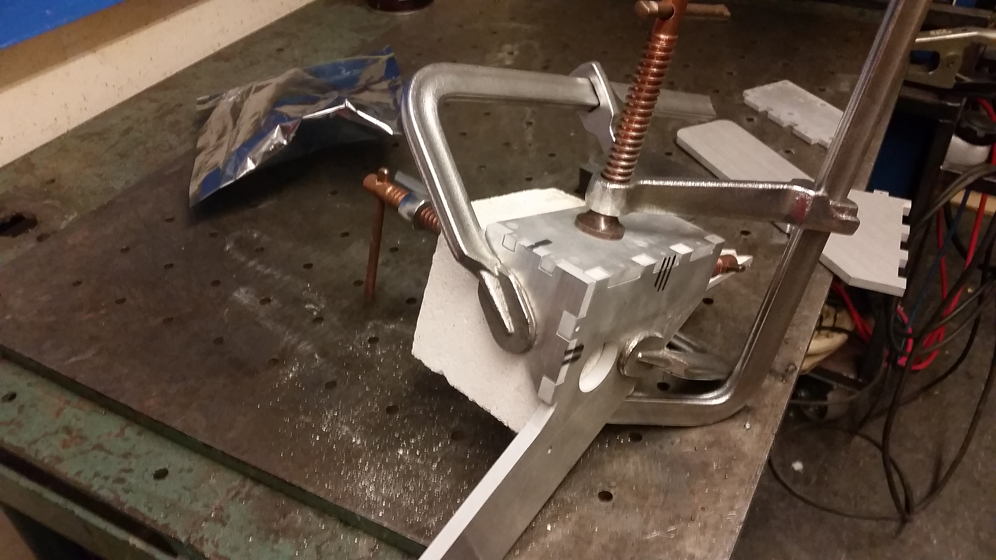
Once I sorted out the fit and spacing, i made a second. Each were hand tapped for 6-32 screws that fit the spacing of the SB50's. The two mounting holes were clearanced for M6 screws that mated to the battery pack. 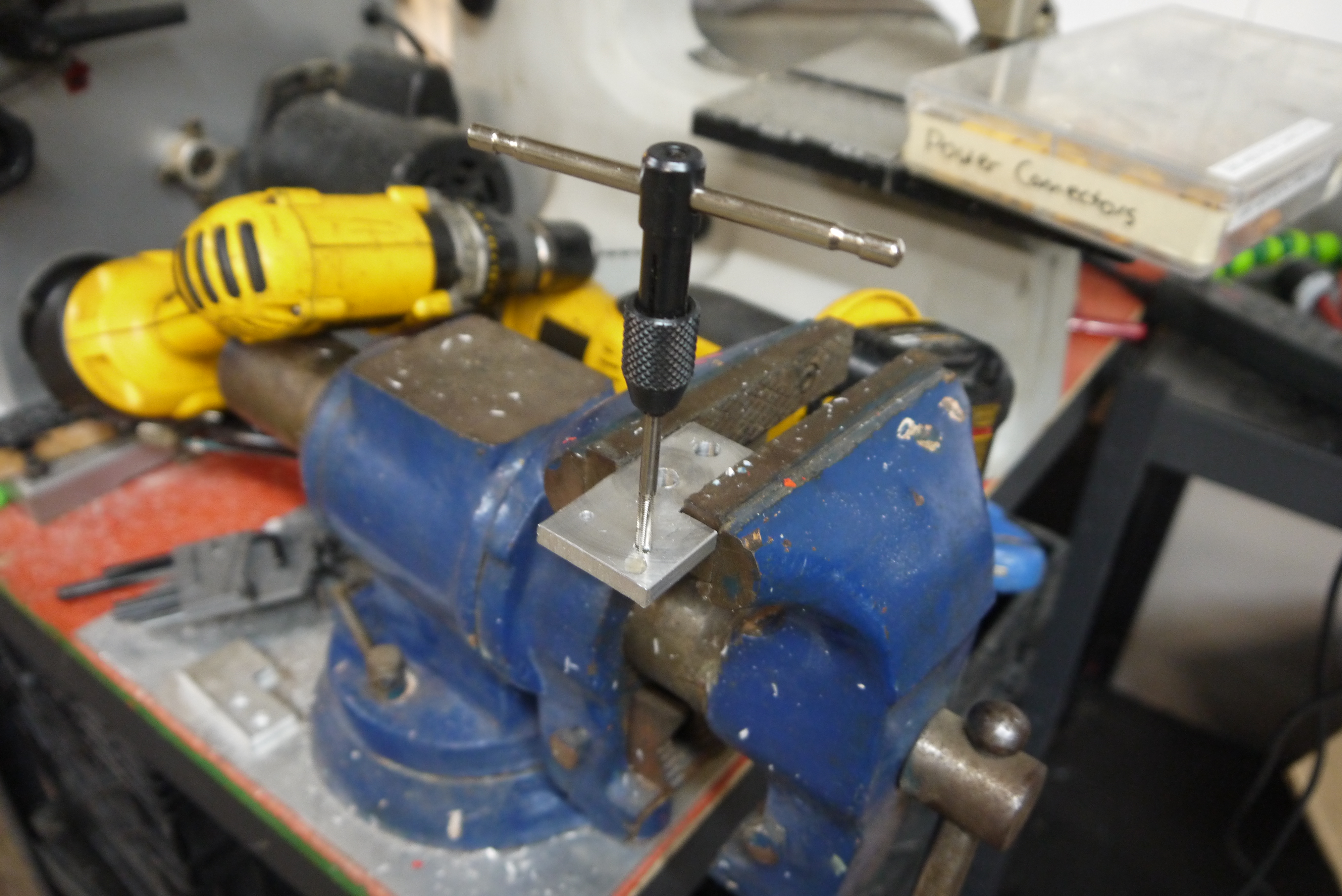
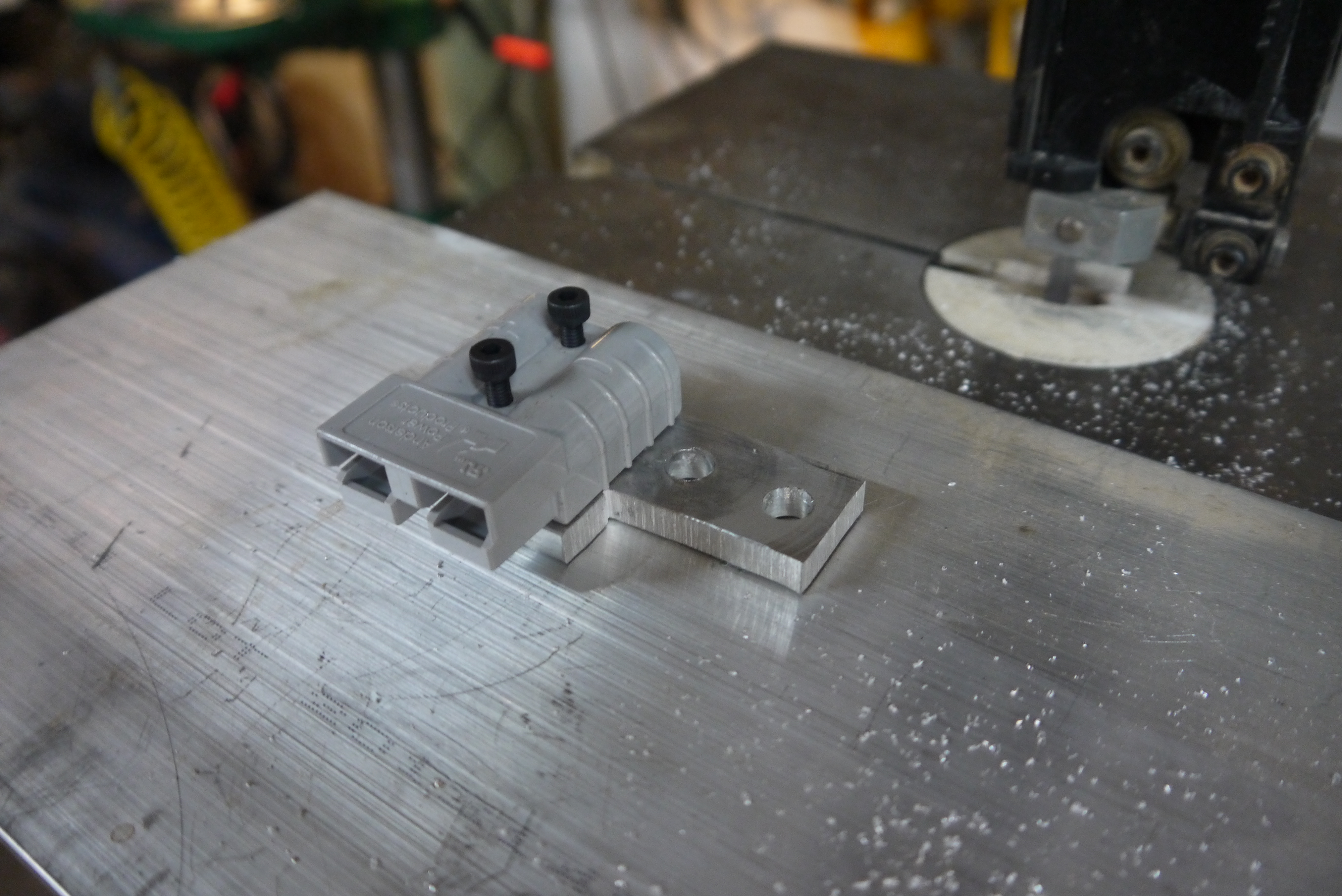
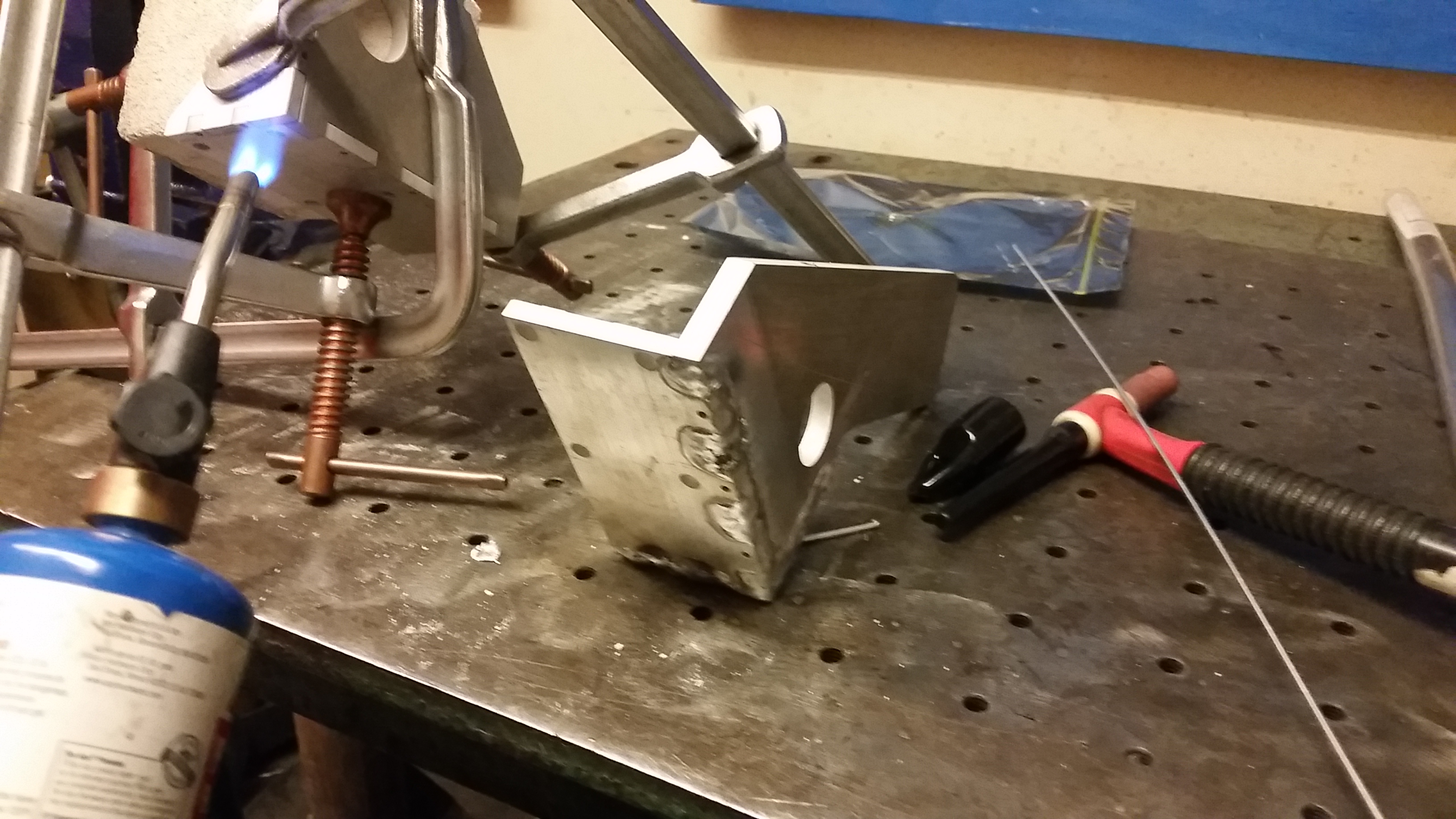
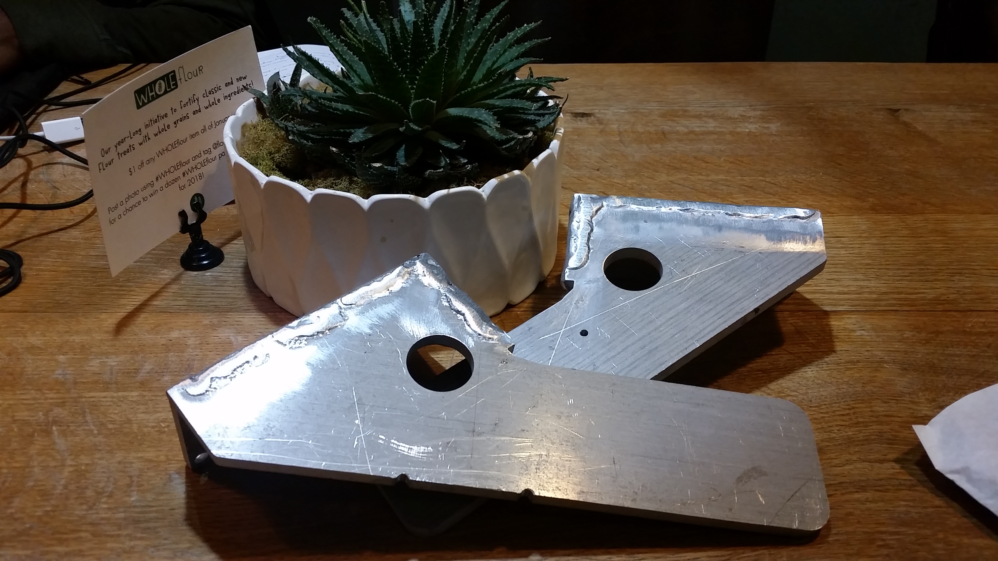
And lo, there's a connector. I opted to use the standard rubber-booty cover for the SB50's when not in use. Upward facing batteries also ensured that quick-release handles could be fitted to disconnect in an emergency. The SB50 6-32 screws were loctite-ed in place and I continued on with wiring the packs (6 awg flexible battery wire) and in-line 100A ring-terminal fuse holders. 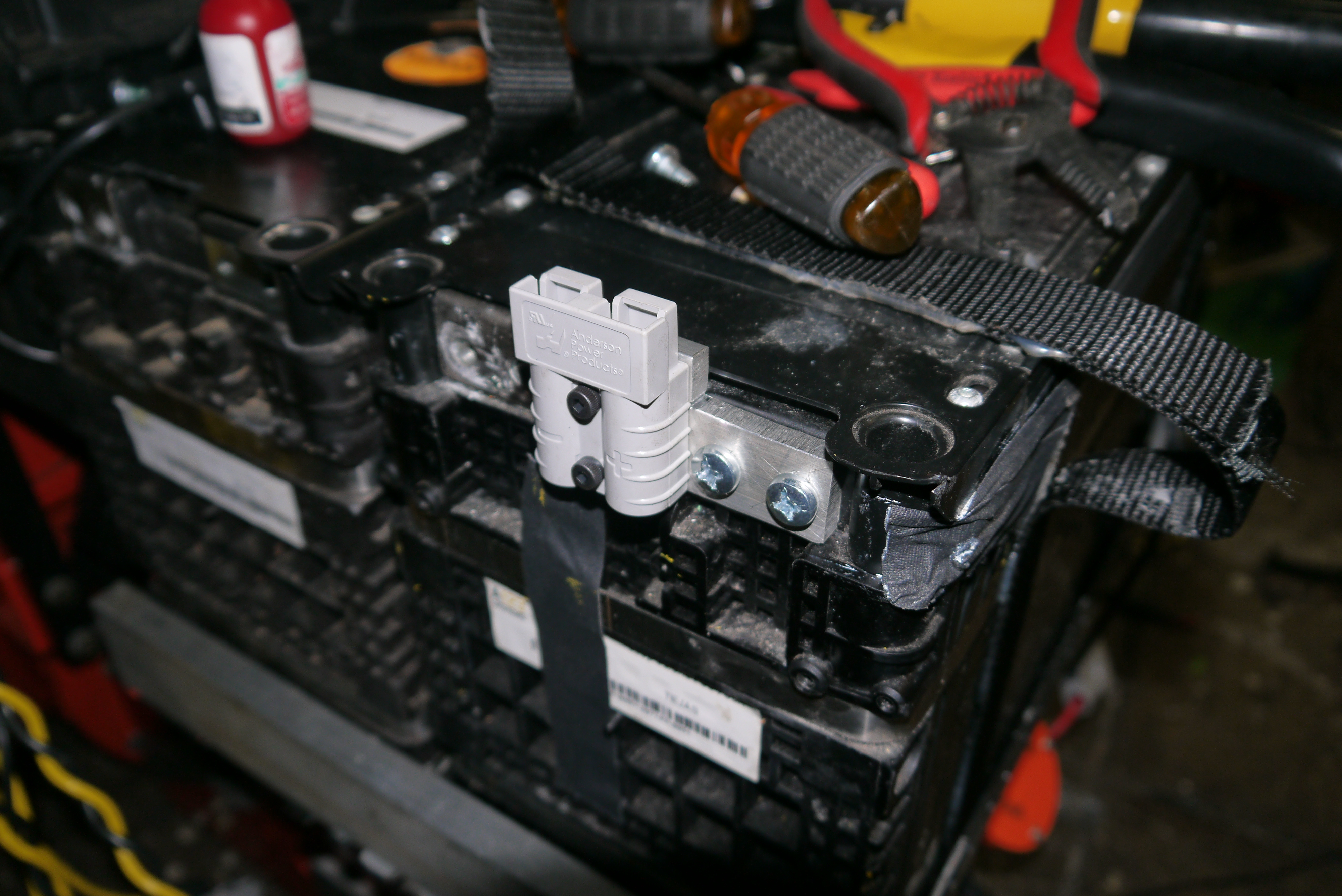
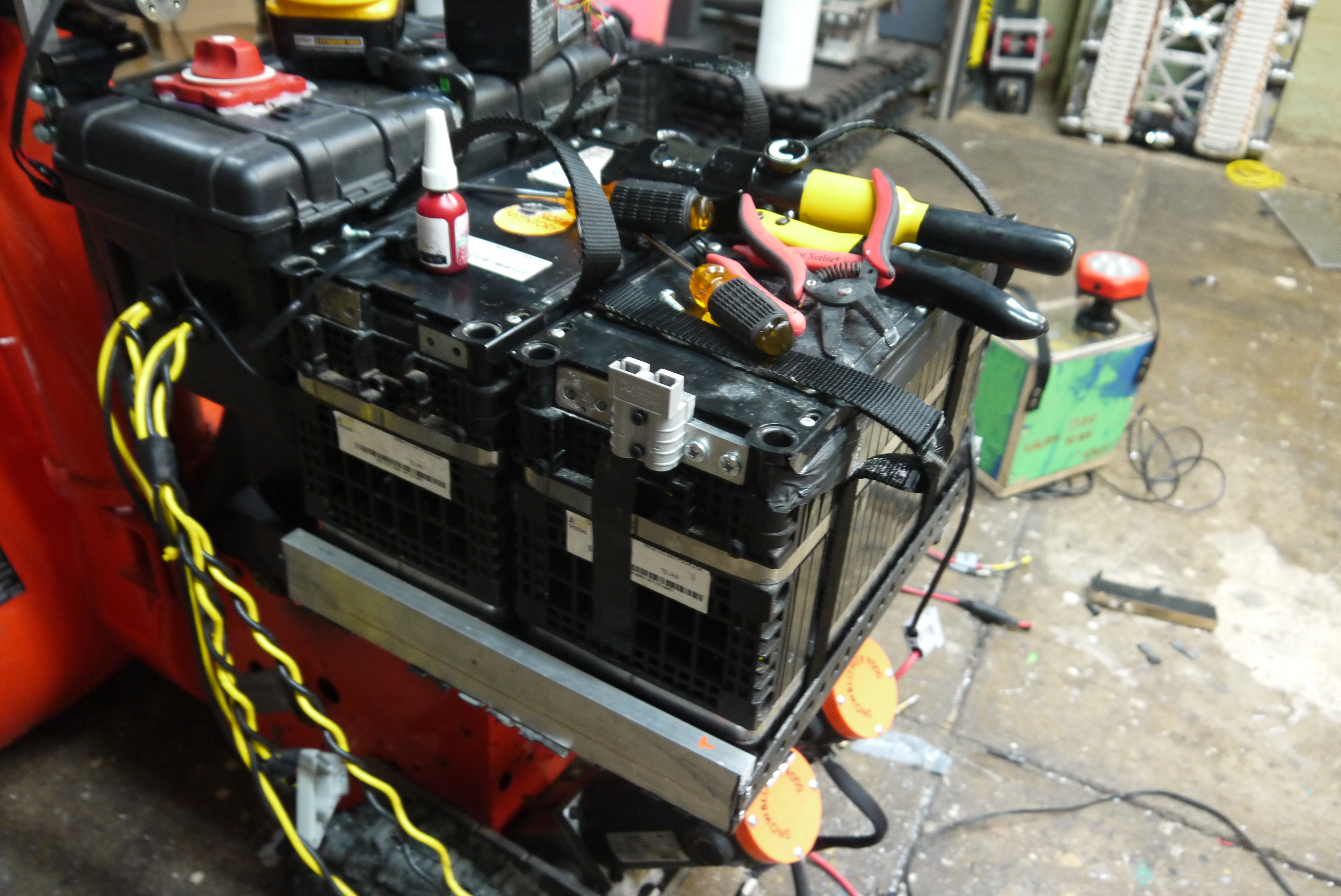
The two batteries fit snugly back behind the motor. This puts a majority of the battery mass over the back wheels, but not extending too far behind the rear wheels. The holsters for the batteries are actually made of surplus shelving brackets and scrap aluminum. 
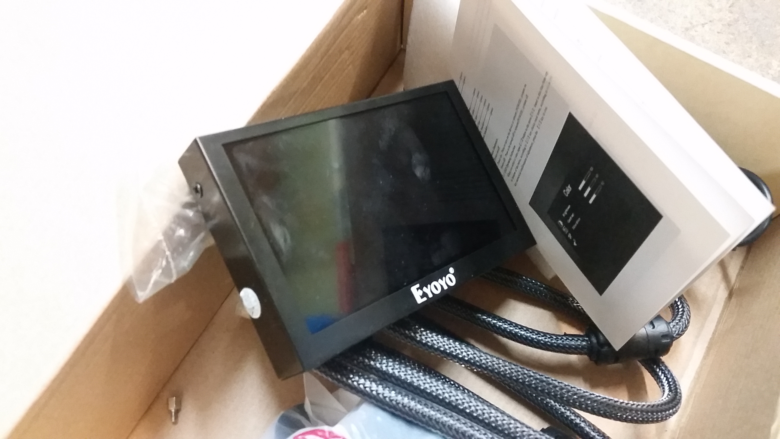
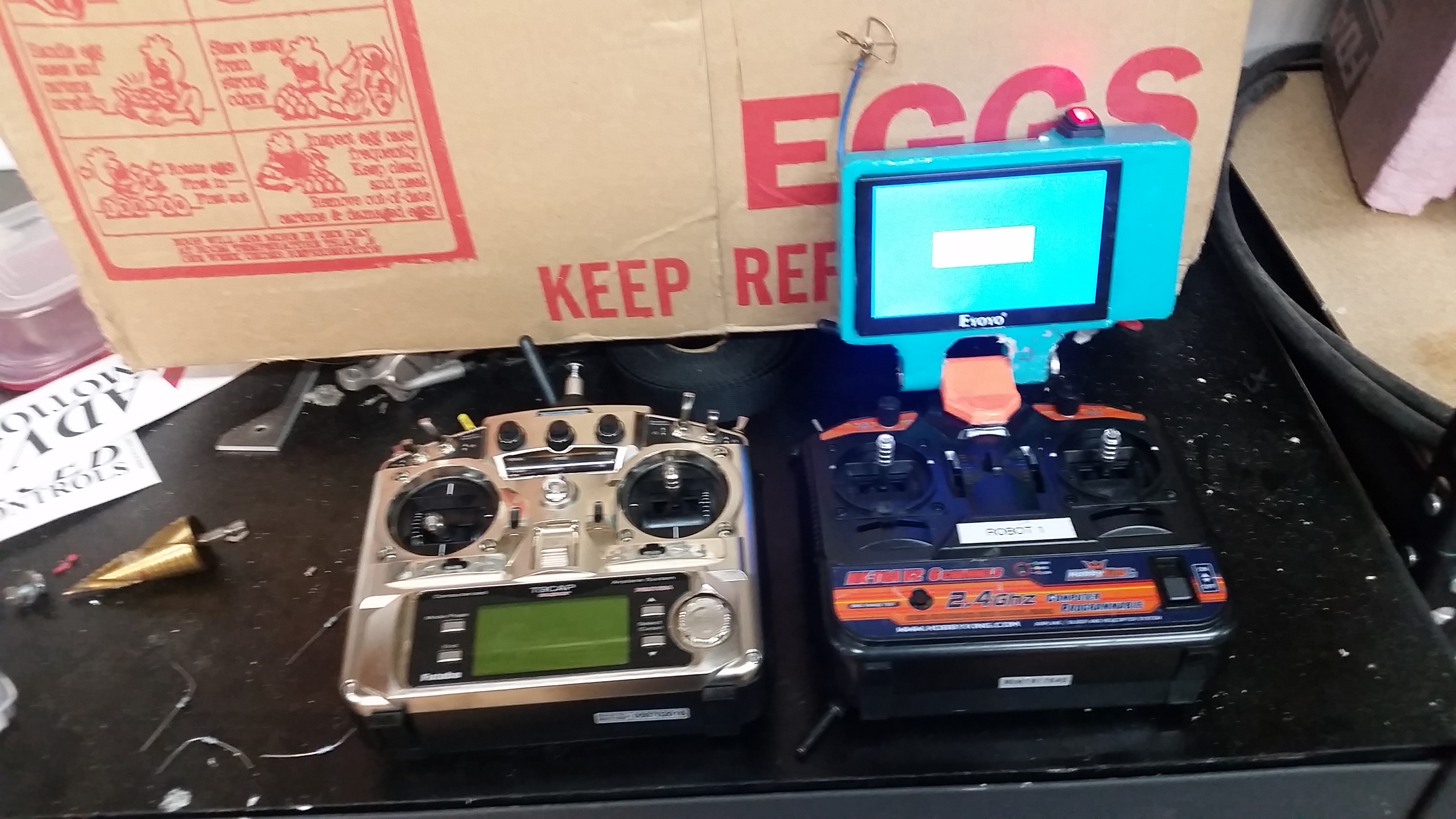
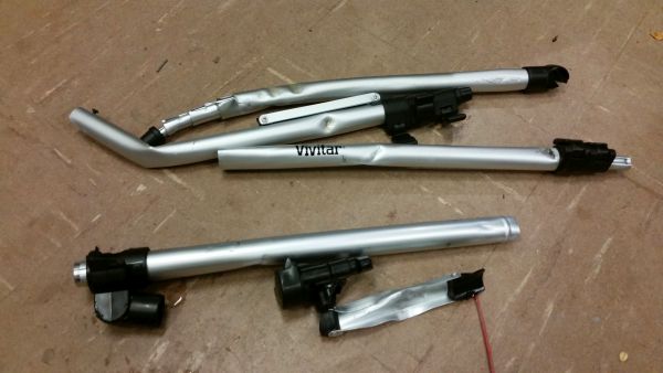
FPV: Live video from a snowblowerVersion 1: A free LCD Monitor and some amazon-grade receivers. Uncle Bayley gifted me an Eyoyo portable LCD. Its 12v powered and has a pile of inputs. Its got a fairly limited viewing angle but it 'does the thing' of displaying an image from a number of sources. 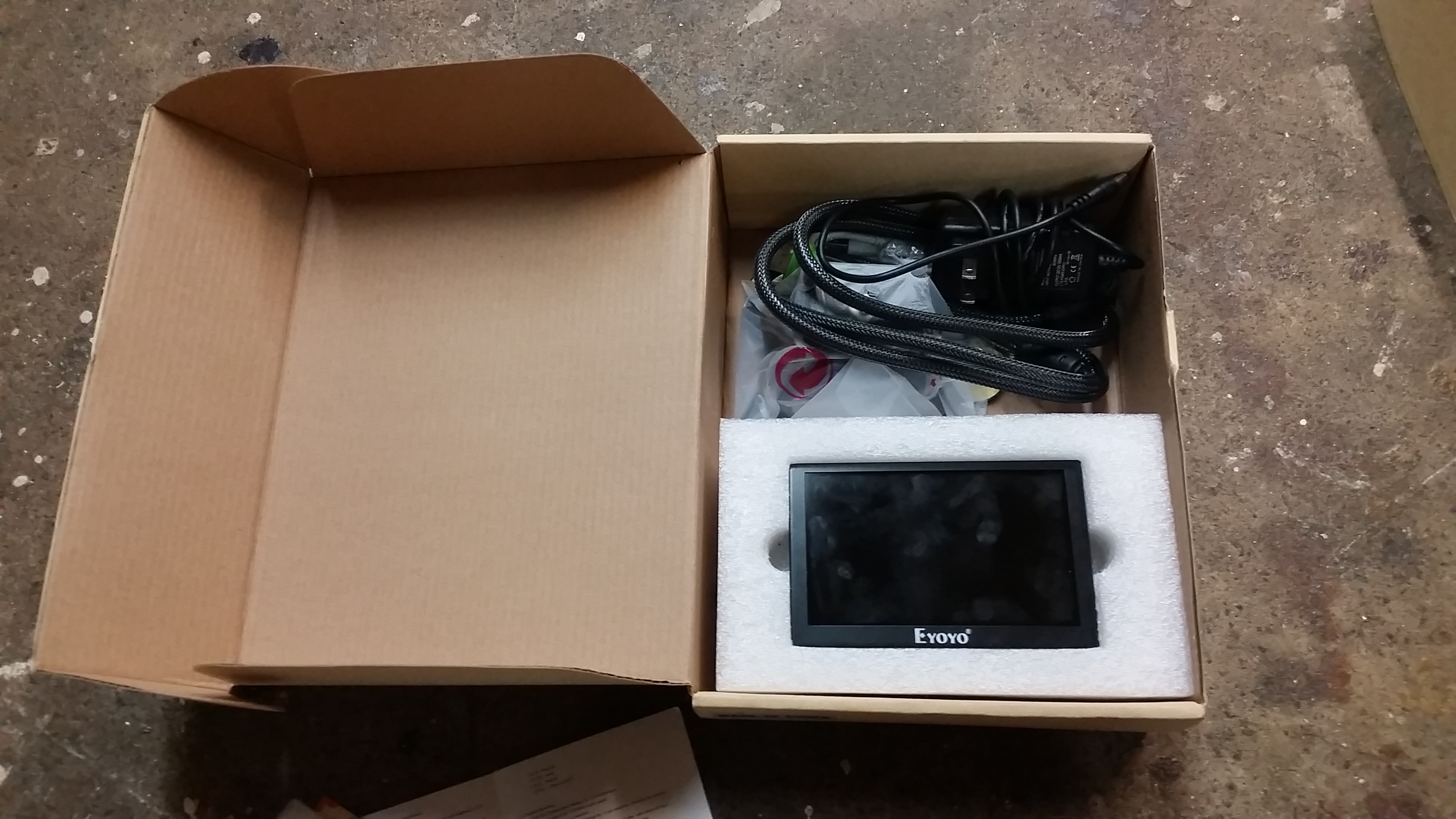
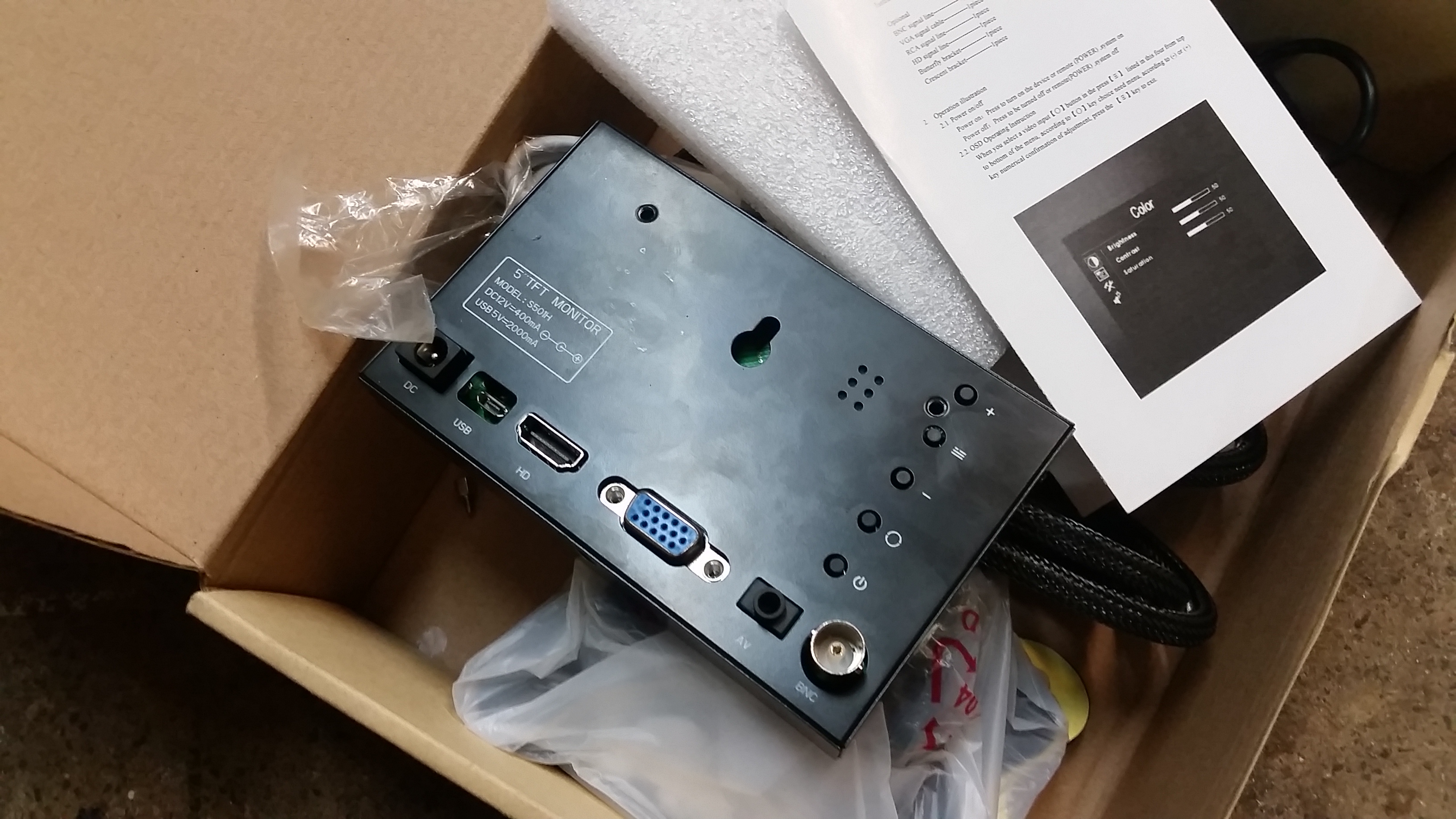
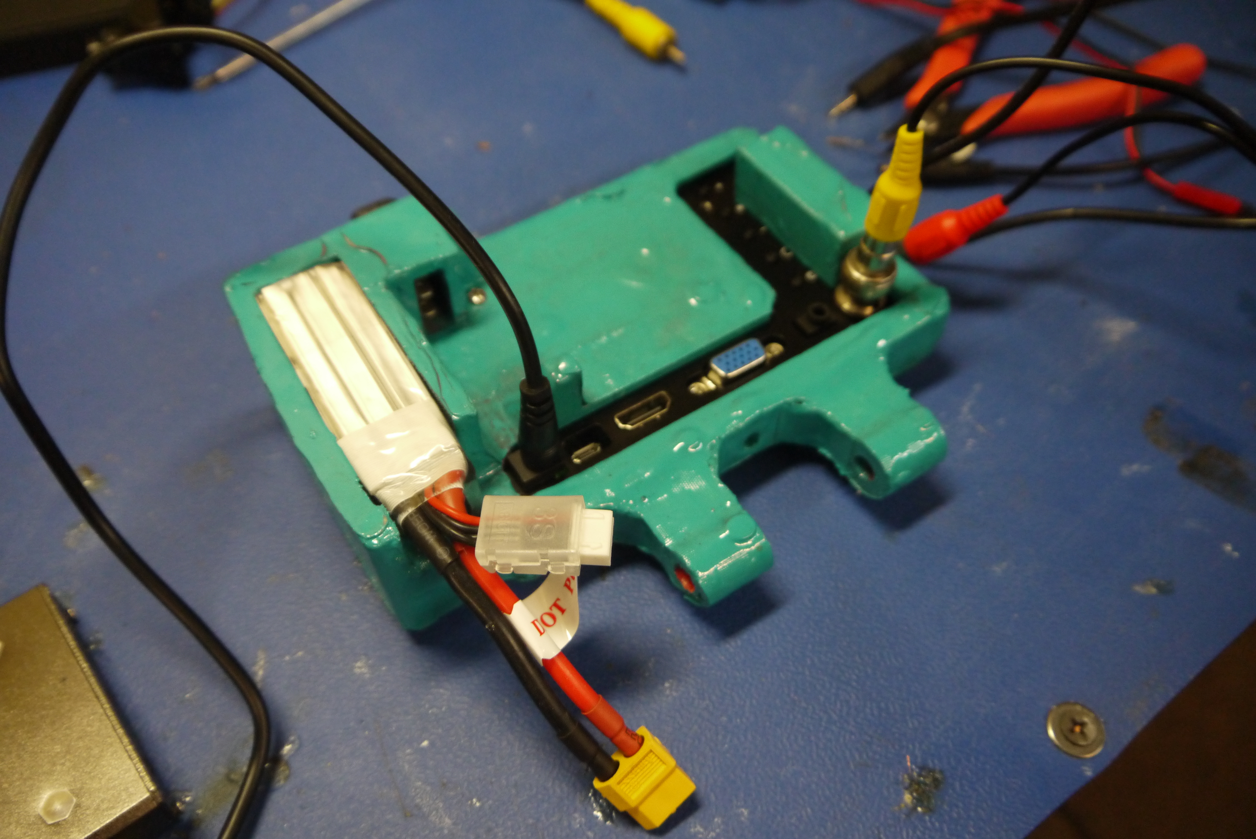
Here's the back side of the monitor. It does have a pile of inputs going for it, there's HDMI, VGA, composite, BNC, and VGA. For whatever reason the composite input phono-jack didn't use standard pin out and as a result there was some confusion. To make everything more compact, I wired the composite feed directly to the onboard hardware. 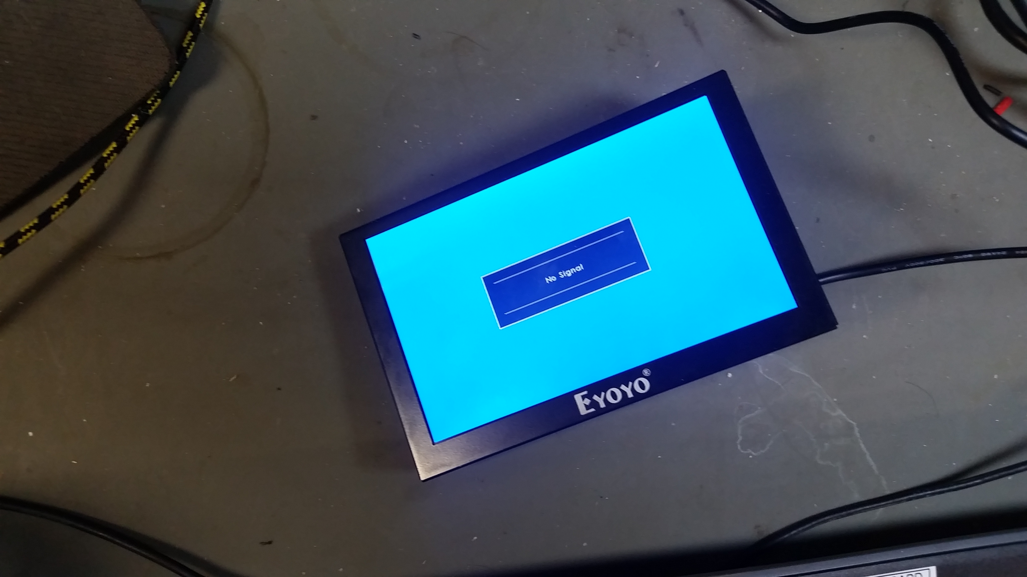
So here's what I came up with: 
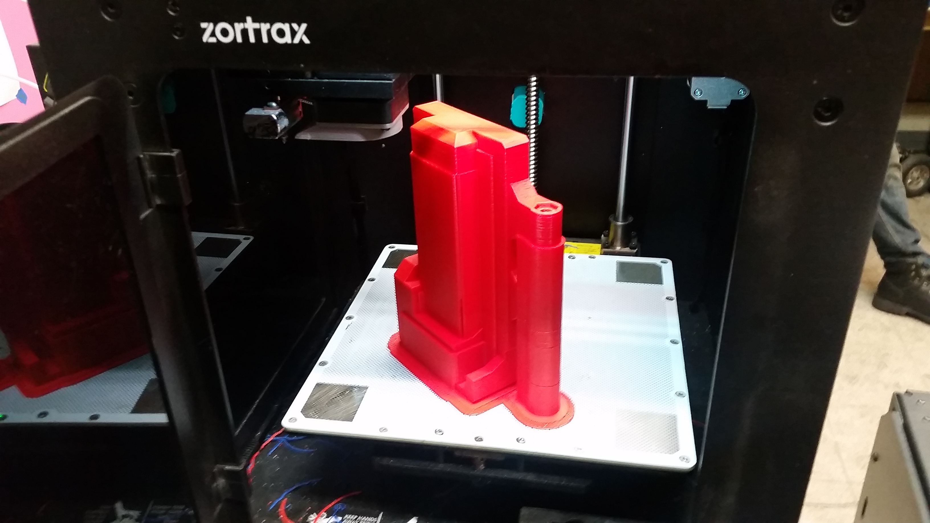
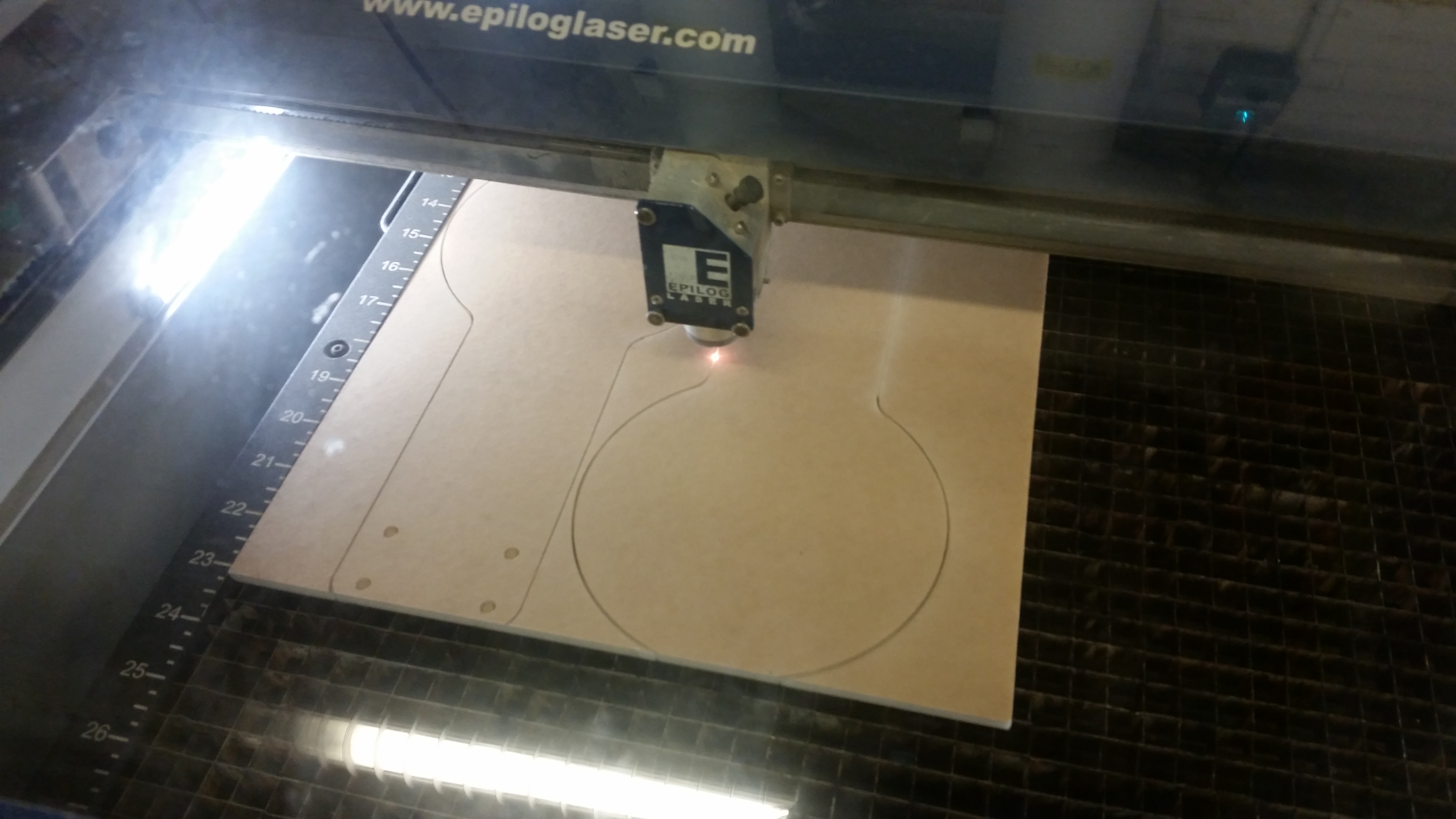
Time to print one large confusing part 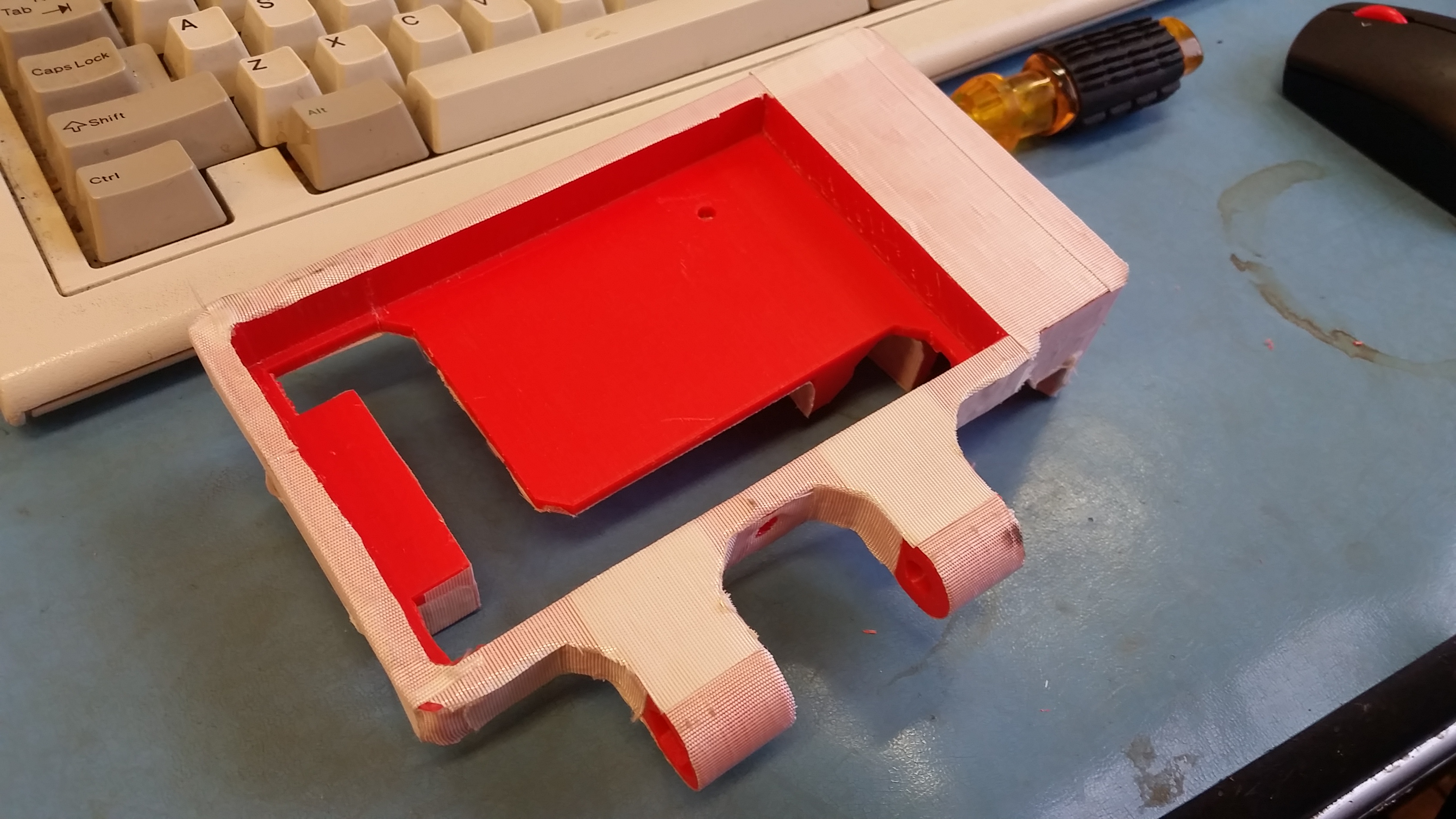
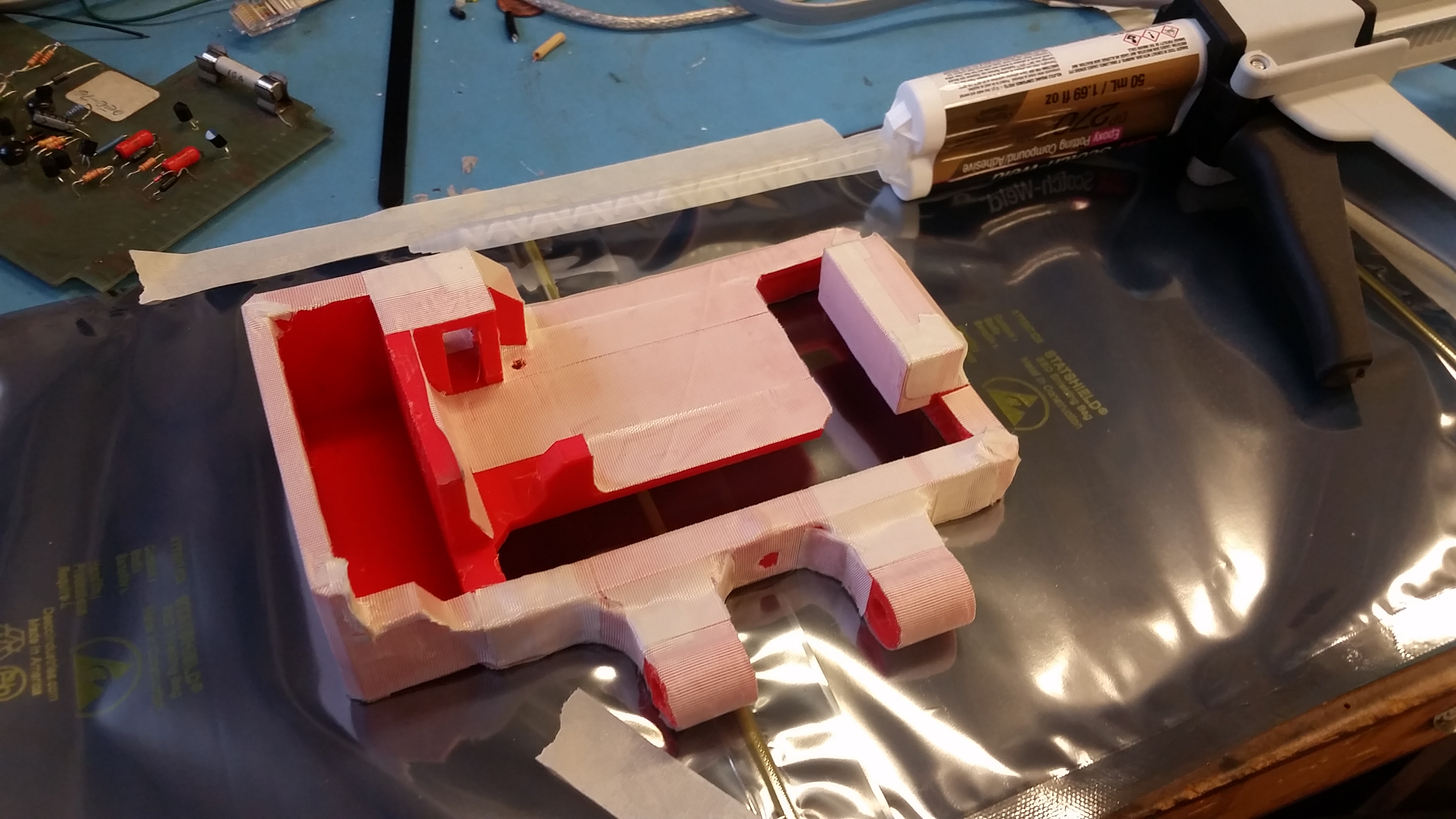
Epoxy covering the fiberglass-tape covered part did do well at forming a hard outer shell but the epoxy didn't quite penetrate the fiberglass and bond with the plastic. It was still a bit more resilliant than the plastic alone. If i were to do this again, laying the fiberglass tape on a layer of epoxy would have helped a lot to increase the structure. 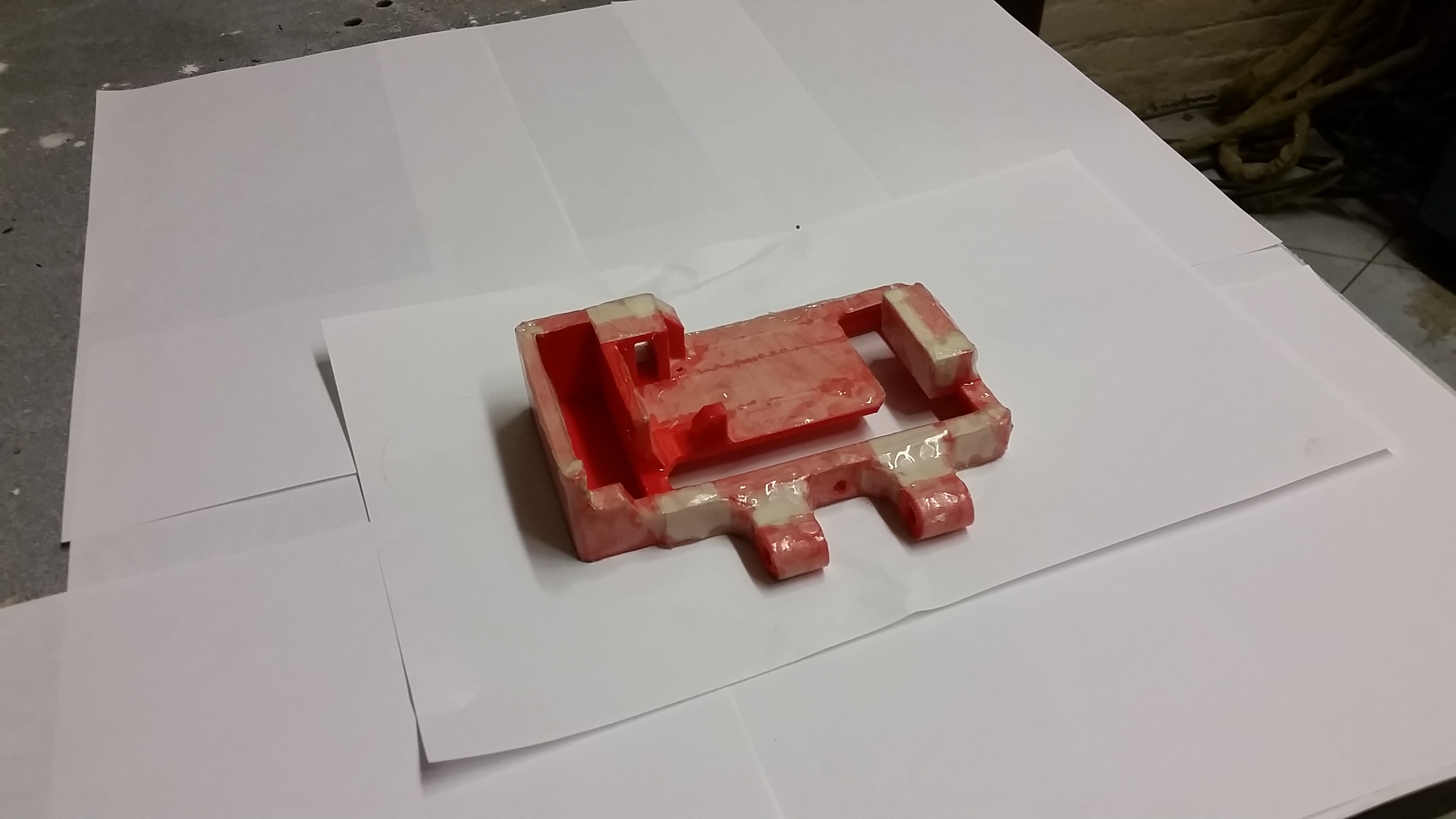
To cover up the epoxy and fiberglass I spray-painted the whole thing teal. It started coming together! The 3S lipo snugly fit inside its cavity, a 12v red-led switch also fit in snug-ly. To reduce the number of protrusions in the back of the display, I opened the case to tie in connections in a more direct fashion. 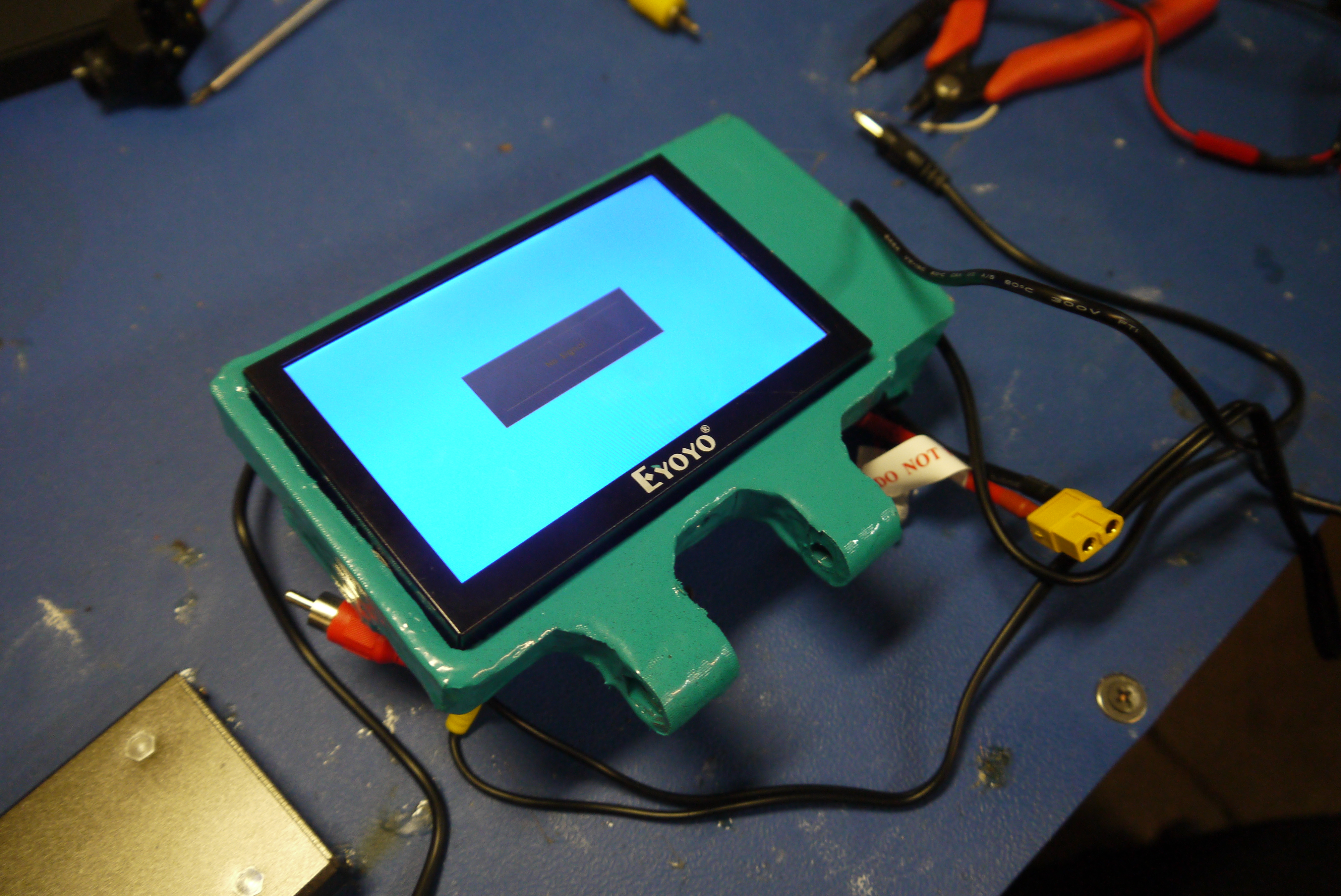
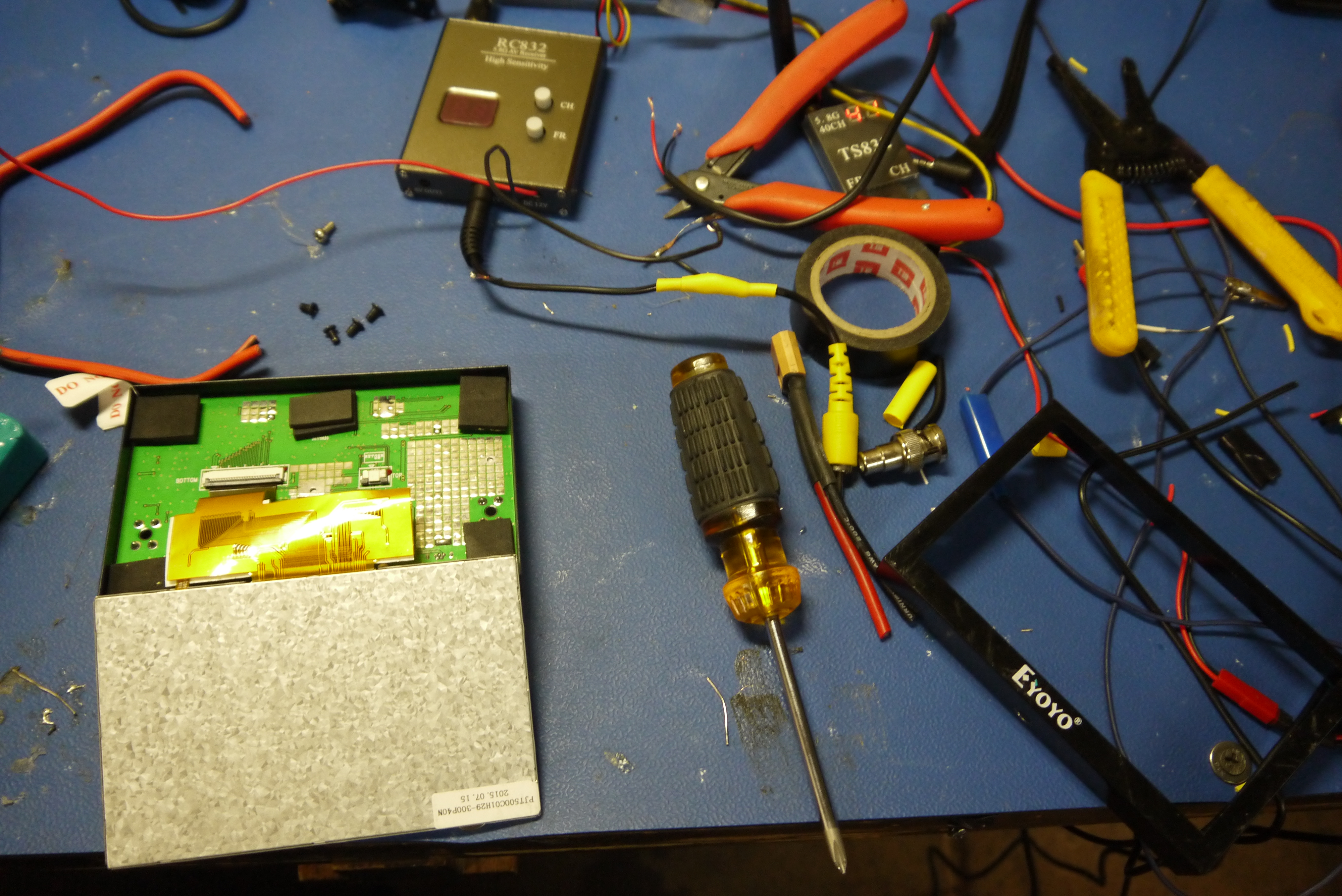
Time to open things up and not terribly destroy everything on the monitor. The BNC-composite adapter was a bit huge, and given that it was doubtful this would ever return to a previous normal state, i opted to wire directly to the board. While i was there I decided to remove the 12v connector as well and patch in directly. Honestly not a lot of hardware on the board, pretty impressively a single part acting as the media converter and LVDS driver. 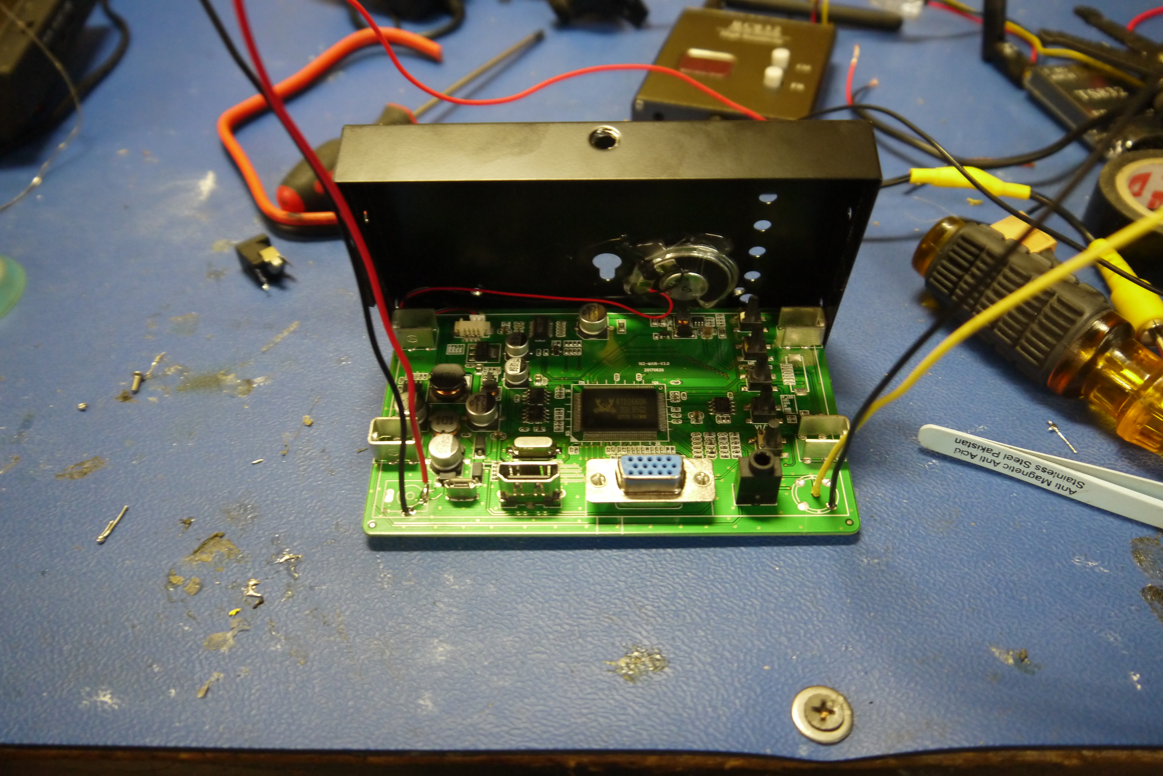
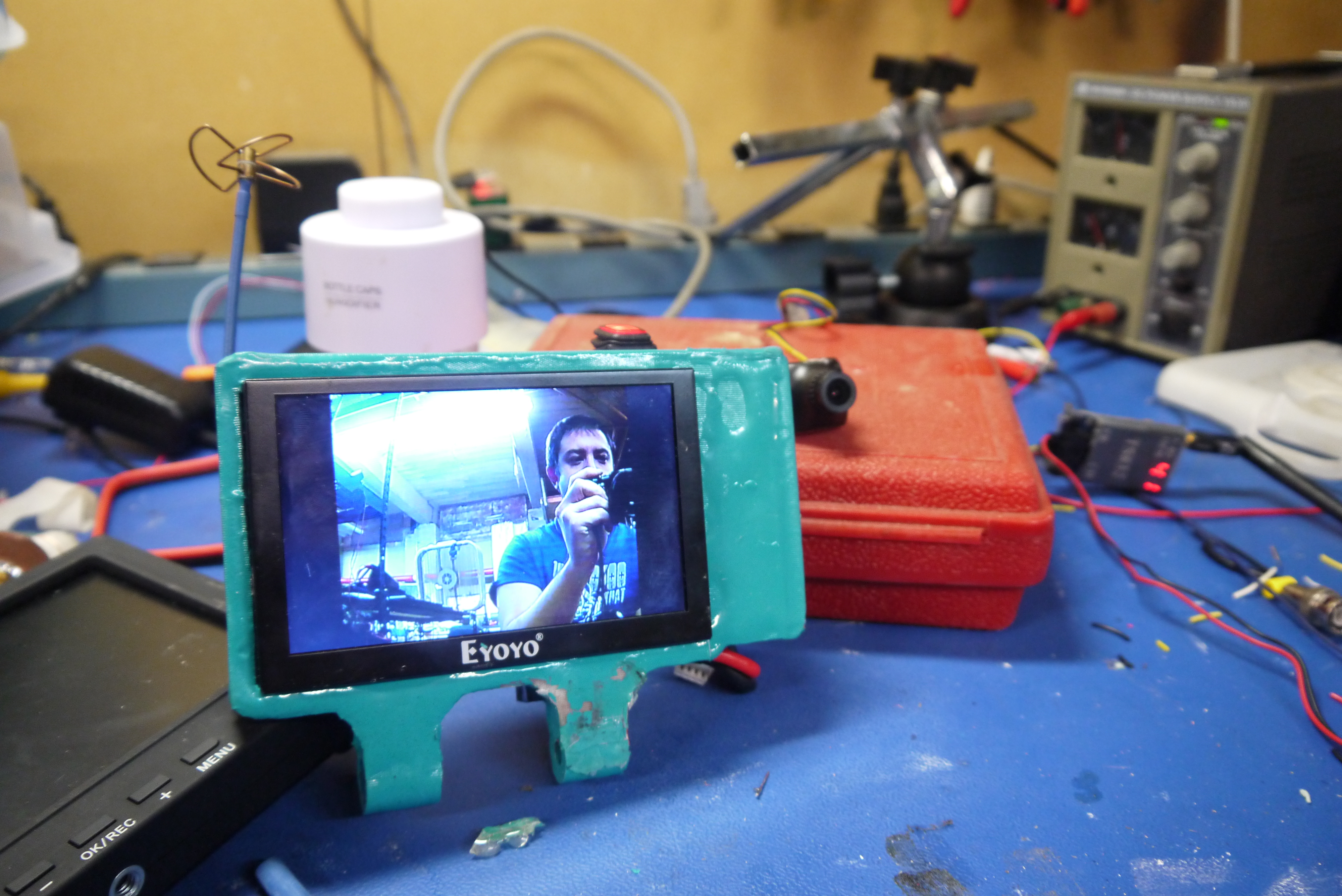
Buttoned back up and lo, it displays an image! As composite video does not support wide-screen i had the monitor set up for 4:3, Later on i opted for having the monitor stretch the 4:3 to 16:9, as the black bars on the side of the screen weren't' too pleasing to the eye. Buttoned back up and lo, it displays an image! As composite video does not support wide-screen I had the monitor set up for 4:3, Later on I opted for having the monitor stretch the 4:3 to 16:9, as the black bars on the side of the screen weren't' too pleasing to the eye. 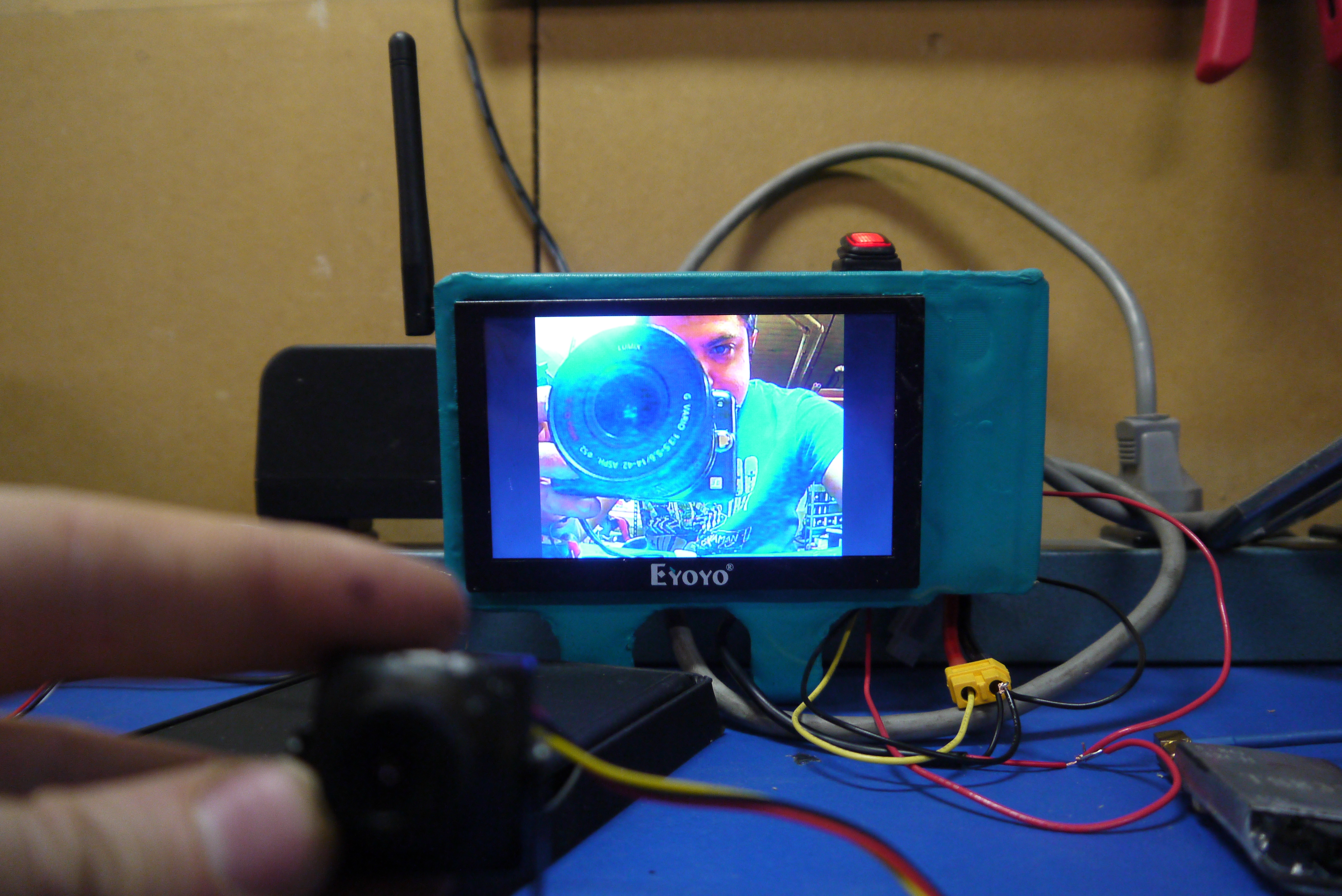
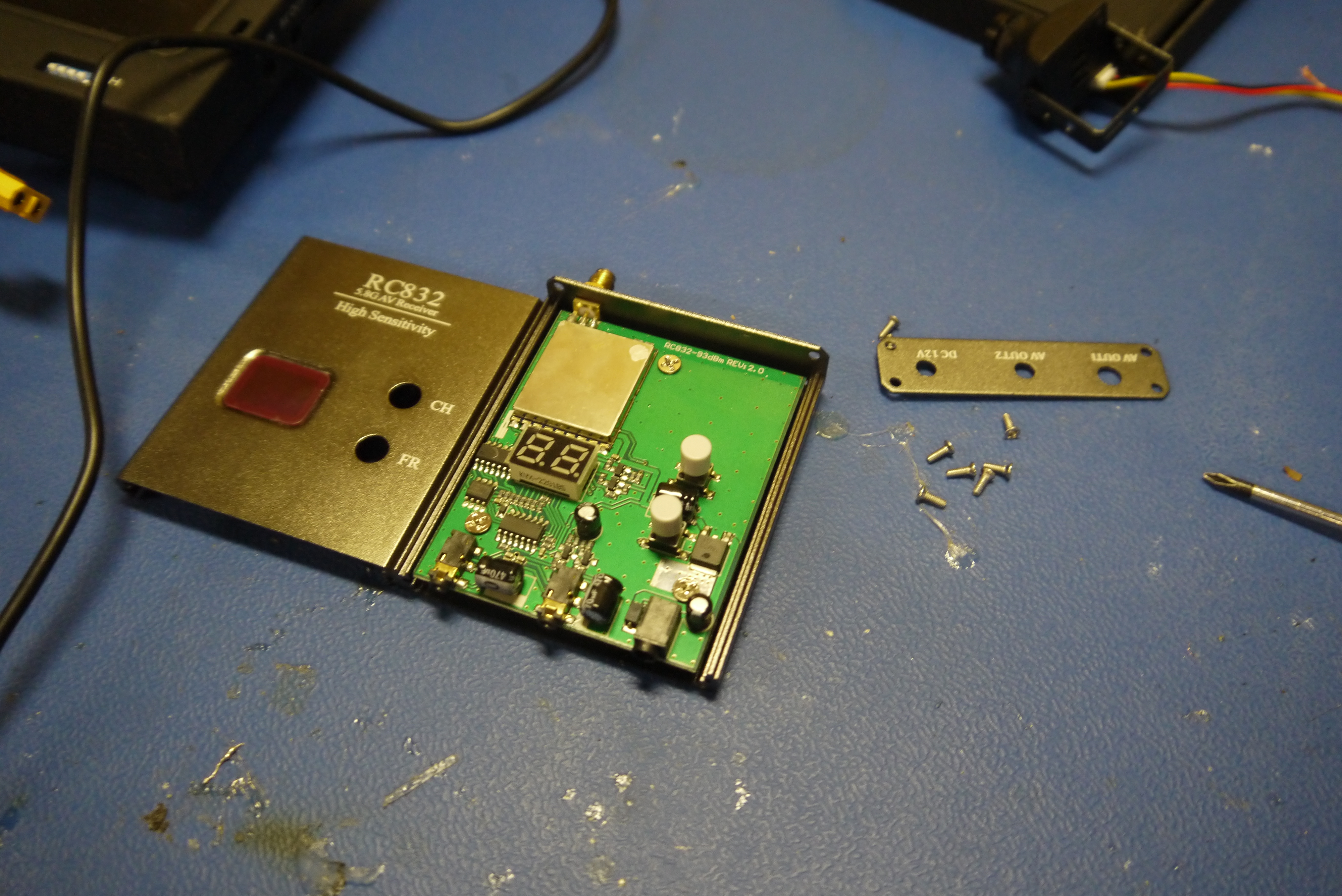
Lets hard-wire the receiver 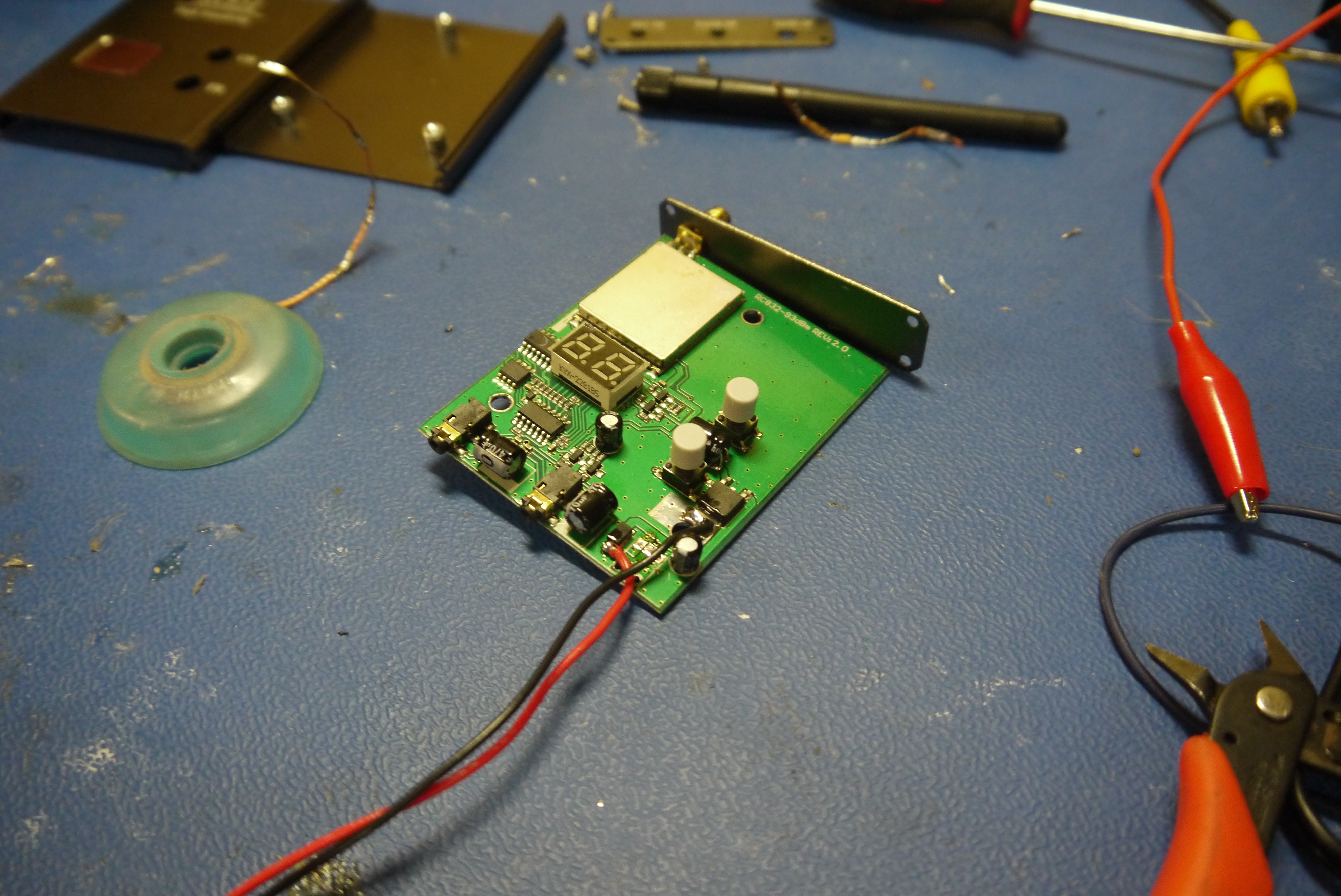
With the monitor mounted its pretty reasonable. I ended up enabling 16:9 instead of 4:3 as the two blank areas on the already tiny screen looked sillyier than the stretched out image. The hardware mount to the transmitter has a fairly heavy load on it, to secure the bolt mount I used some fairly intense epoxy, with both surfaces heavily roughed up. Note that the right-side hand tensioning nut is fully removeable and the monitor can function stand-alone, which is fairly convienient. Shown far right is the view from the snowblower (right behind the chute) 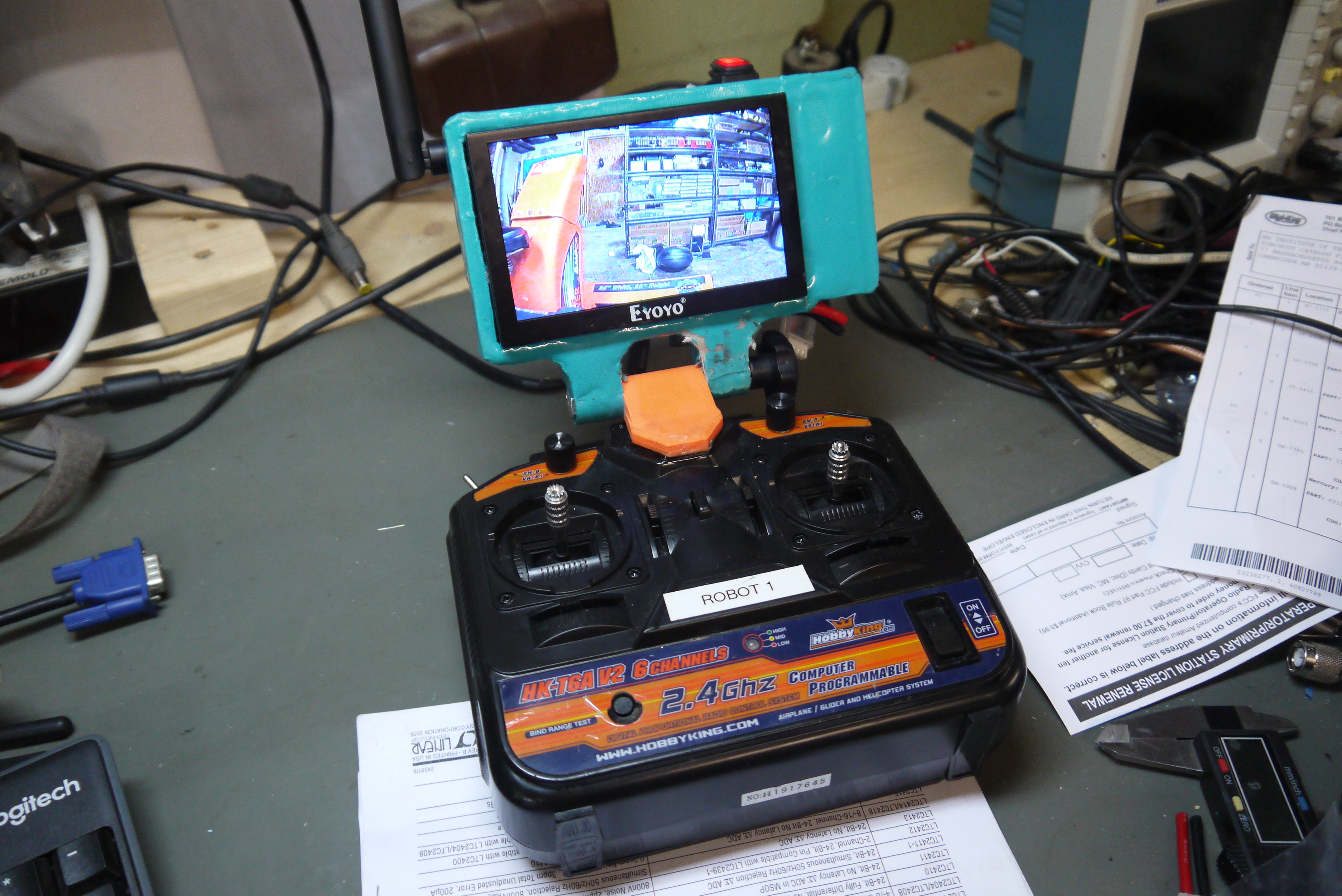
Next up: A 'quick and dirty' fpv camera transmitter. The nice part about the hobby FPV market is that everything is quite tiny. I had a small hammond box sitting about and fit the camera with wide FOV lens inside, an on-off switch. 12v indicator lamp and 5.8ghz transmitter with the SMA connector facing outwards. I opted to use a 2 conductor JST for the power input. There was fair amount of hot-melt glue tying everything together. 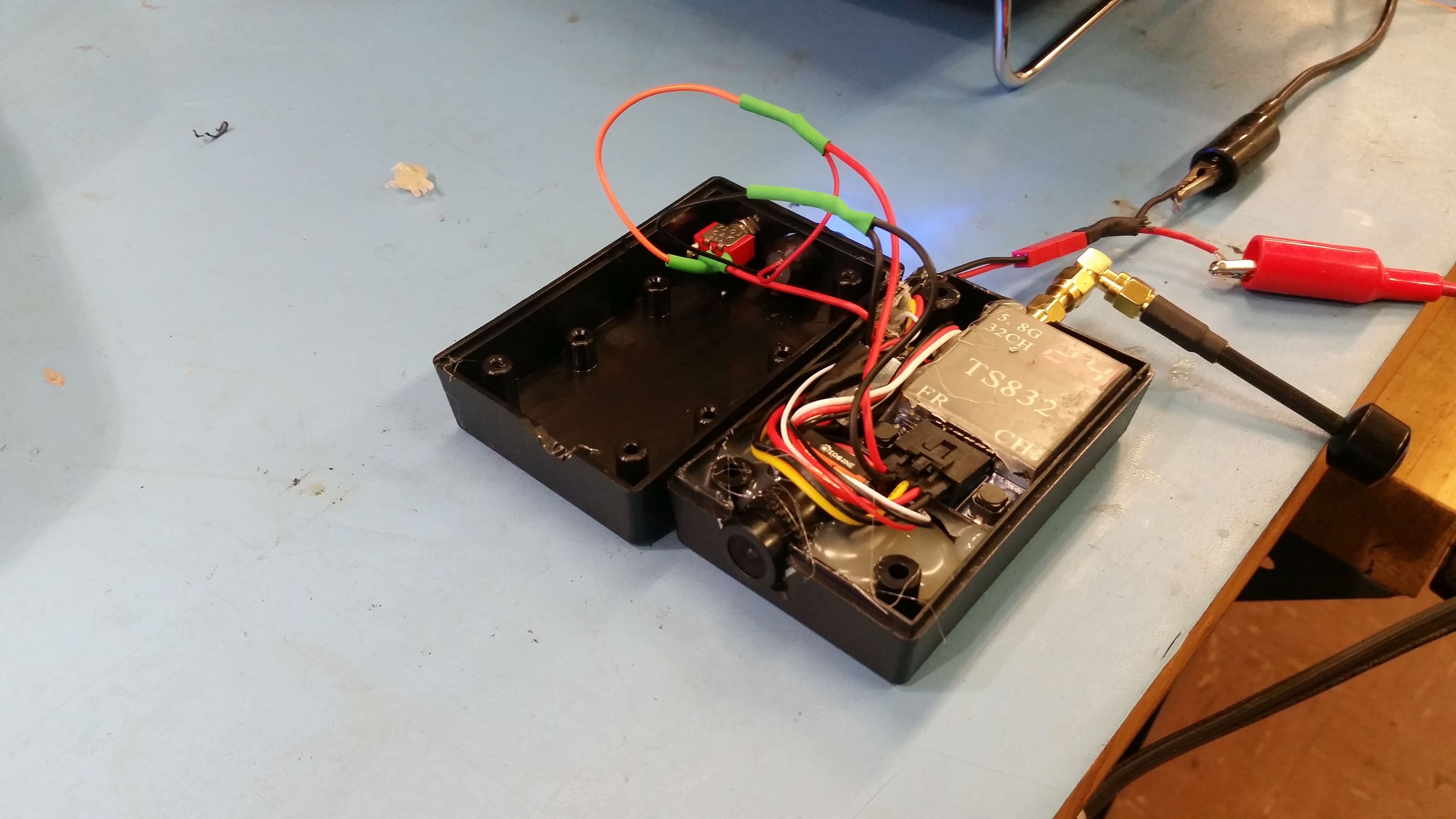
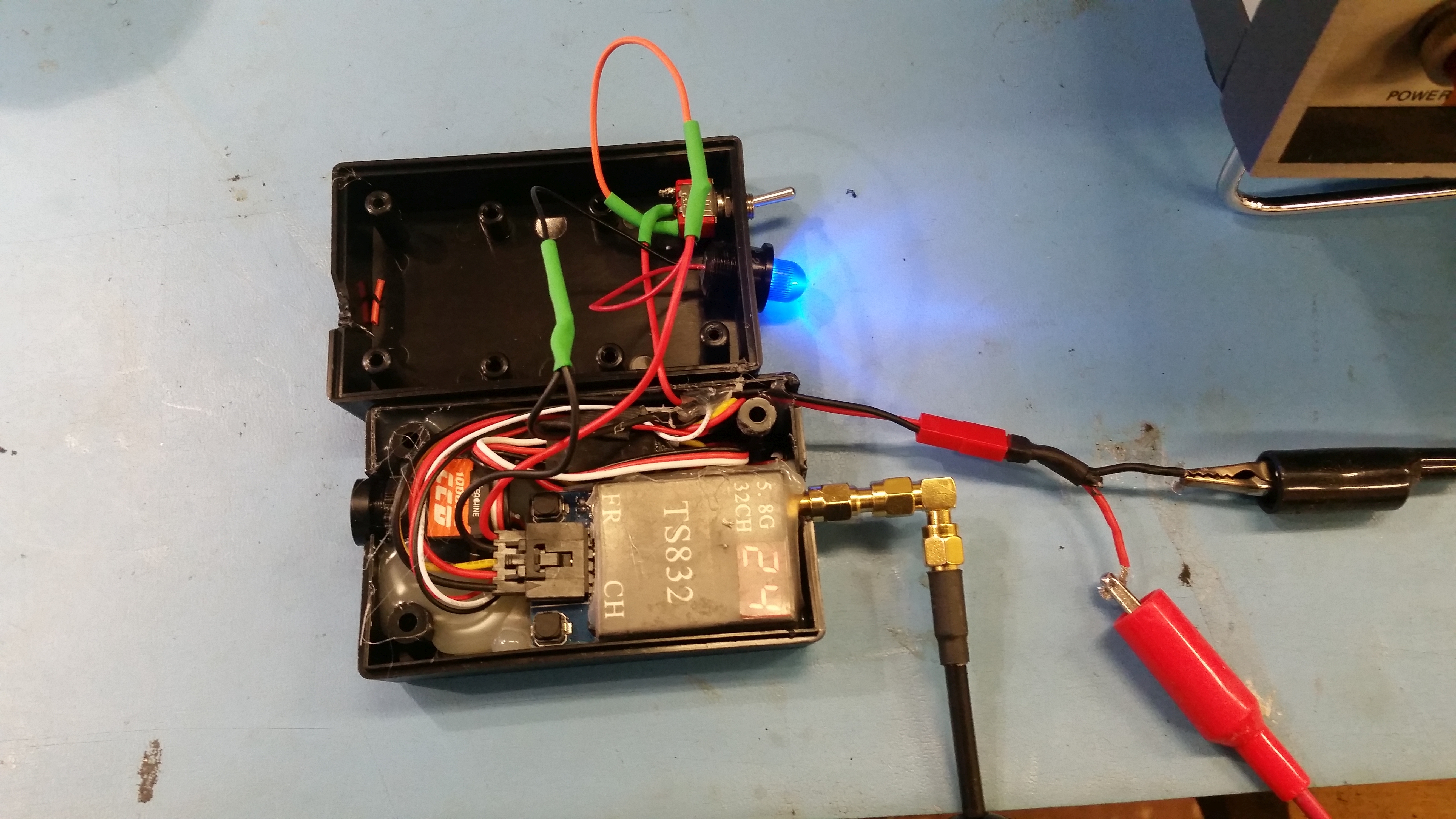
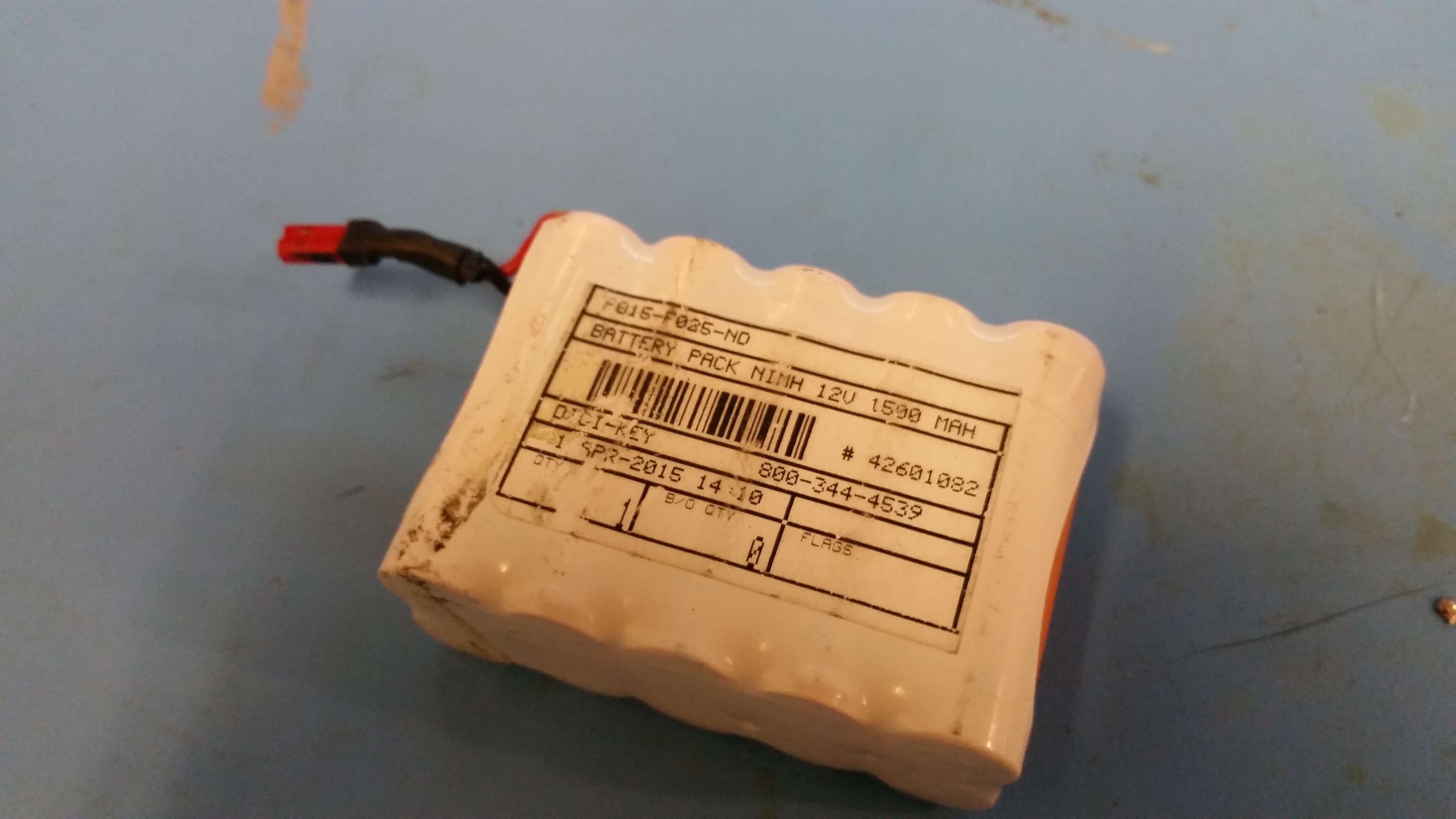
The whole module came out quite adorable, the right-angle SMA and rear mounted switch worked swimmingly. To power the unit, I opted for a NiMh battery pack i had from a previous project. its a 10-cell 1500mAh pack, not a whole lot of capacity, but super straightforward and self-contained. I was a little concerned as NiMh isnt a great chemistry selection for the cold. To play it safe i charged the pack at C/4 (370mA) 
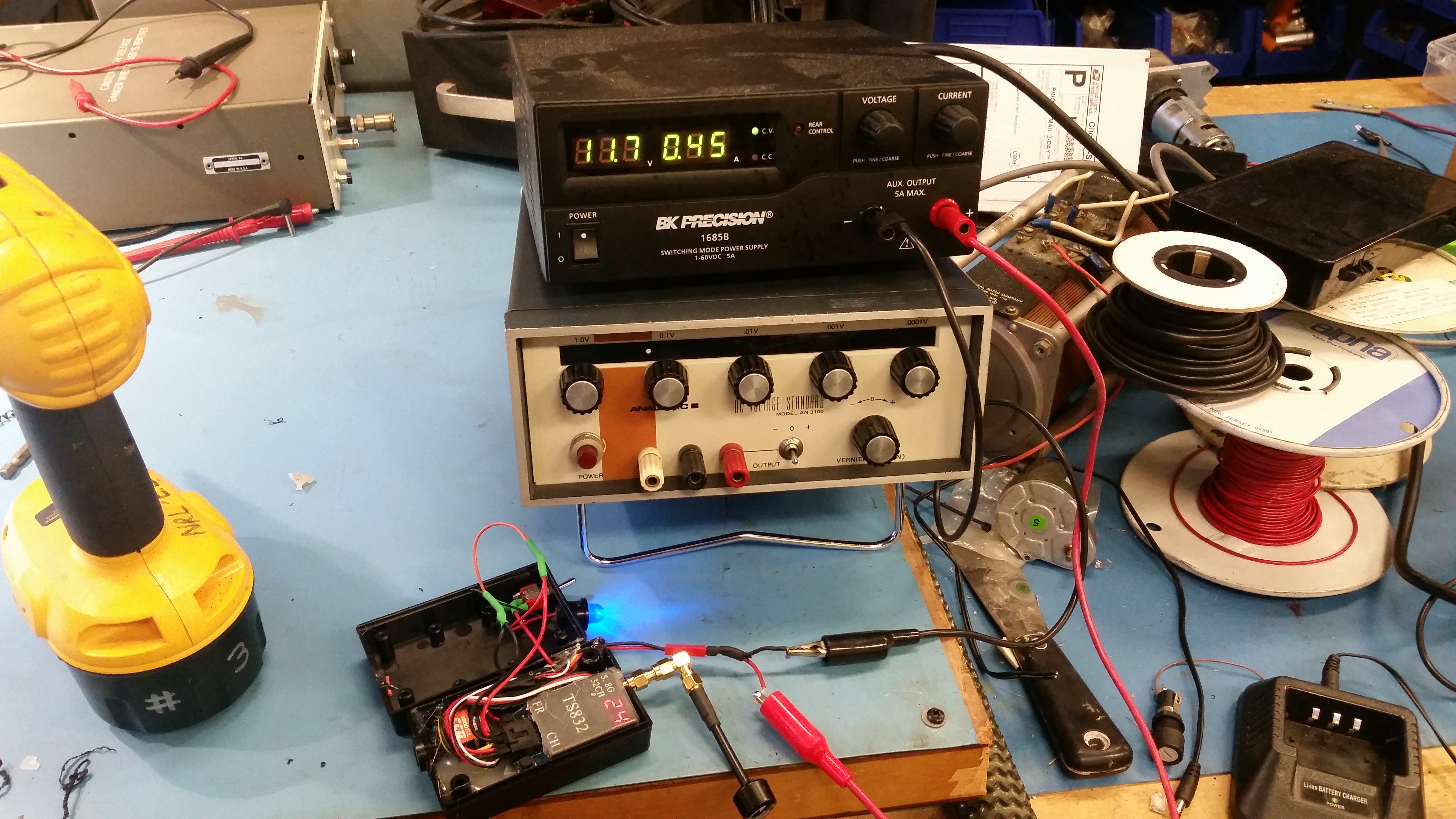
A quick current draw test indicated the whole module, transmitting at ~100mW with the power indication led on was 450mA at 11.8v, so a C/3 discharge for the NiMh pack. In an ideal case thats 3+ hours of transmitting but in the cold I would probably be limited to an hour or so. For temporary mounting I used hook loop tape. This worked reasonably well but a better solution was needed for operation an hour, as the camera vibrated-off a few times. 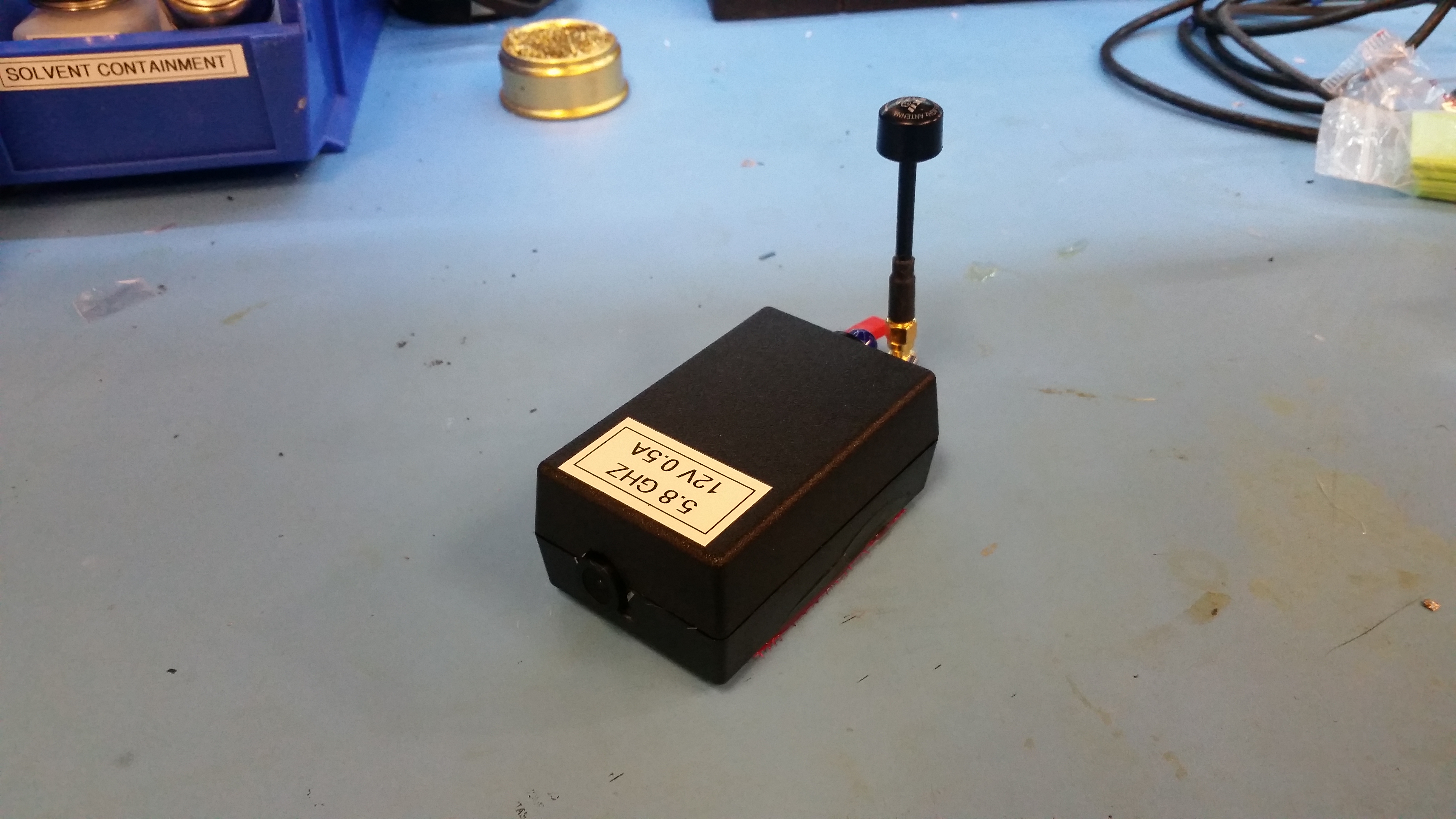
FPV Range Test FootageLate at night I tested the FPV setup. 5.8GHZ is incredibly common, but unfortunatley very directional. Its also quite effectivley attenuated by atmospheric moisture. I went for a walk down a fairly straight road in a more industrial area to show what the range looked like. Admittedly this was a moving reciever with a fixed transmitter, while the snowblower would be a moving transmitter with a fairly fixed reciever. Conventional FPV is pretty horribly quality wise, but quite good at latency. Video was recorded with an android OTG 5.8ghz usb reciever and the free FPVDROID app.
This is what driving over FPV looked like. Video recorded over the FPV link to an android phone using a low cost android UVC compatible reciever [link], and recorded using FPVDROID [link].
Note that when recording with FPV droid, placing your phone in airplane mode before use prevents adverts from displaying and, generally, the software works better. Kinda looking forward to a FOSS implementation.
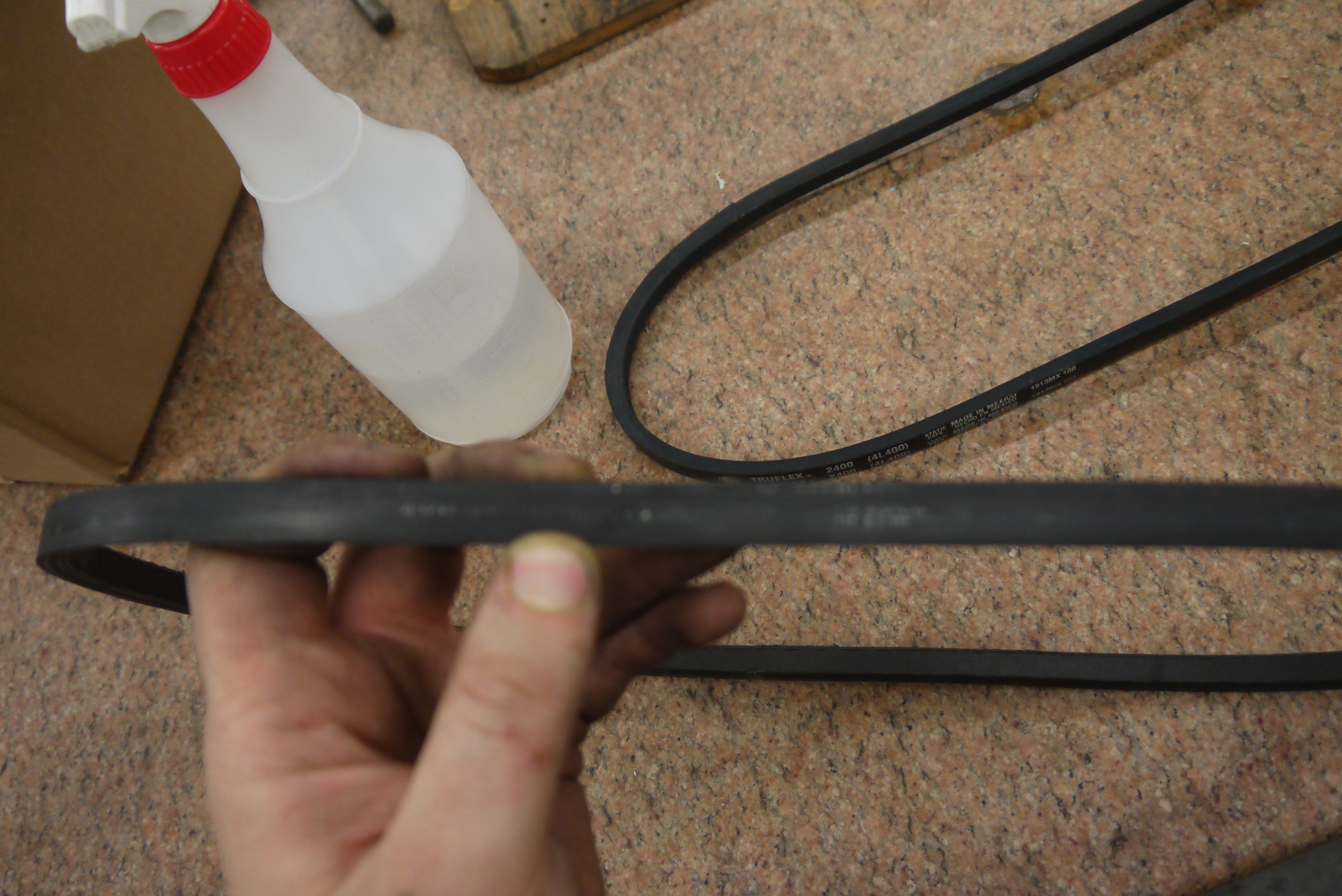
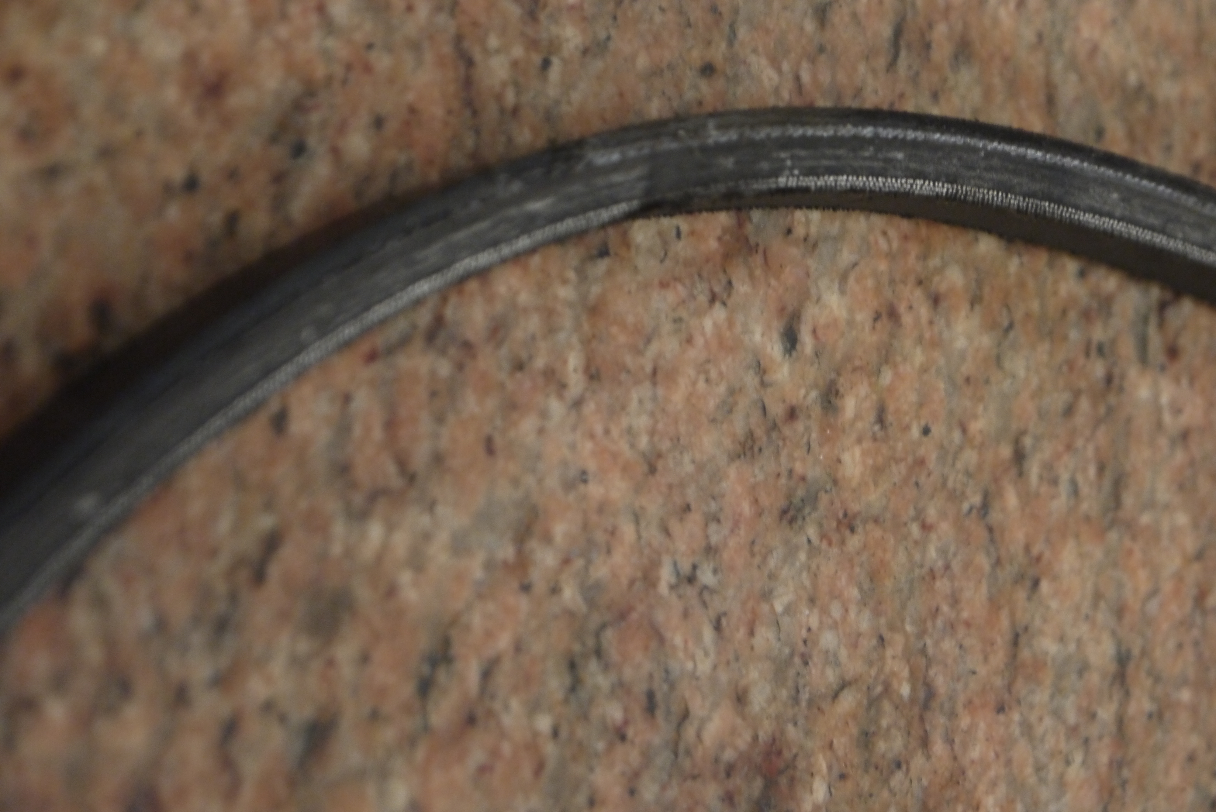
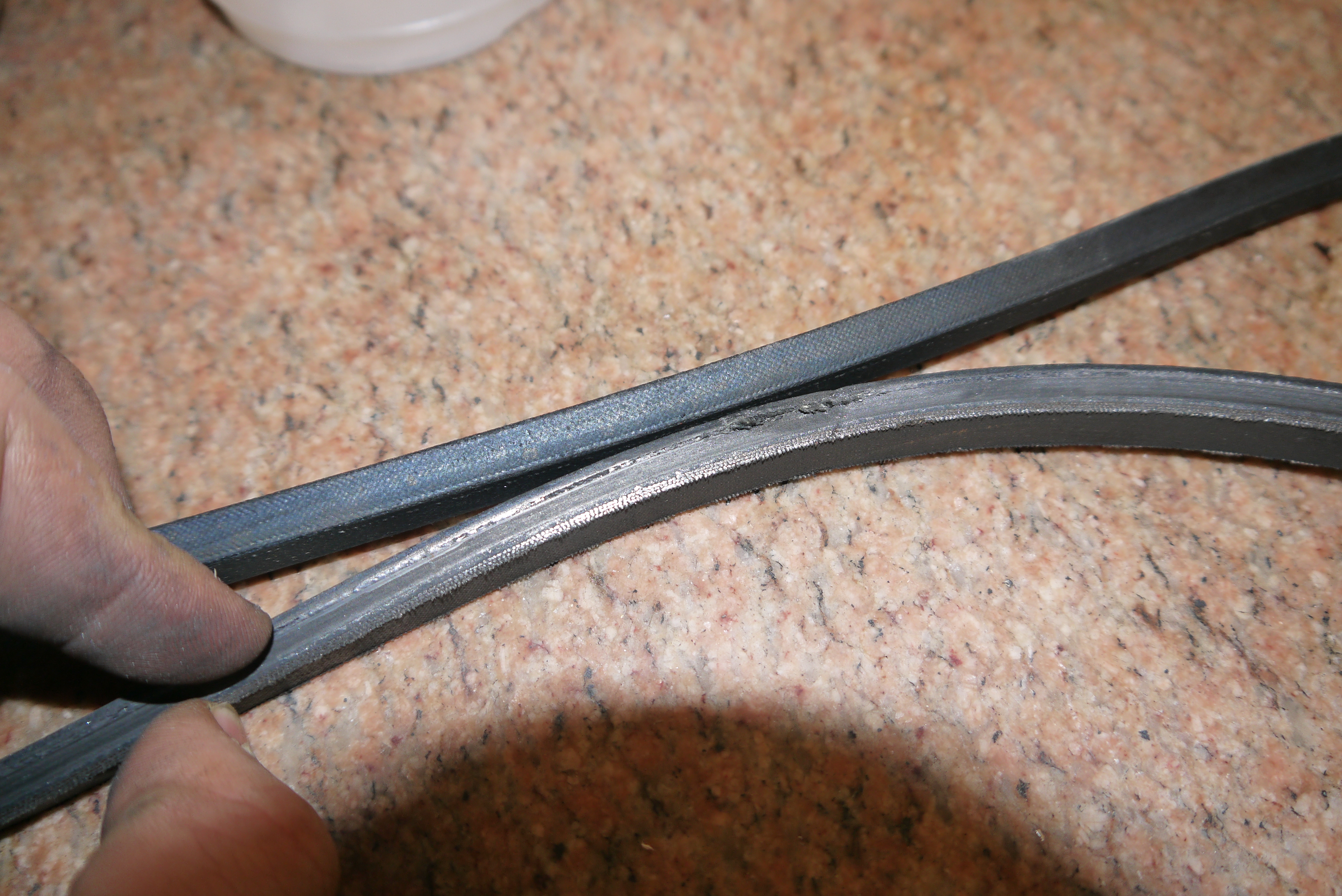
Here's what version one looked like while driving. This was day-after blizzard at a local park. Most of my Day-of blizzard footage was a bit shaky-camera filmed. Note the 'squeeak of sadness' is actually the elderly v-belt. I didnt realize how old it was and how poorly it was preforming. This was replaced right afterwards with a remarkably better performance. Version 1 Observations and Thoughts:What Needed Improvement:
|


Post your comments! |
|
Comment Box loading
|