
Dane Kouttron
Project Started: 11/2022
Quick Project: Universal 150W E-Bike Battery to Lenovo Slim Tip Adapter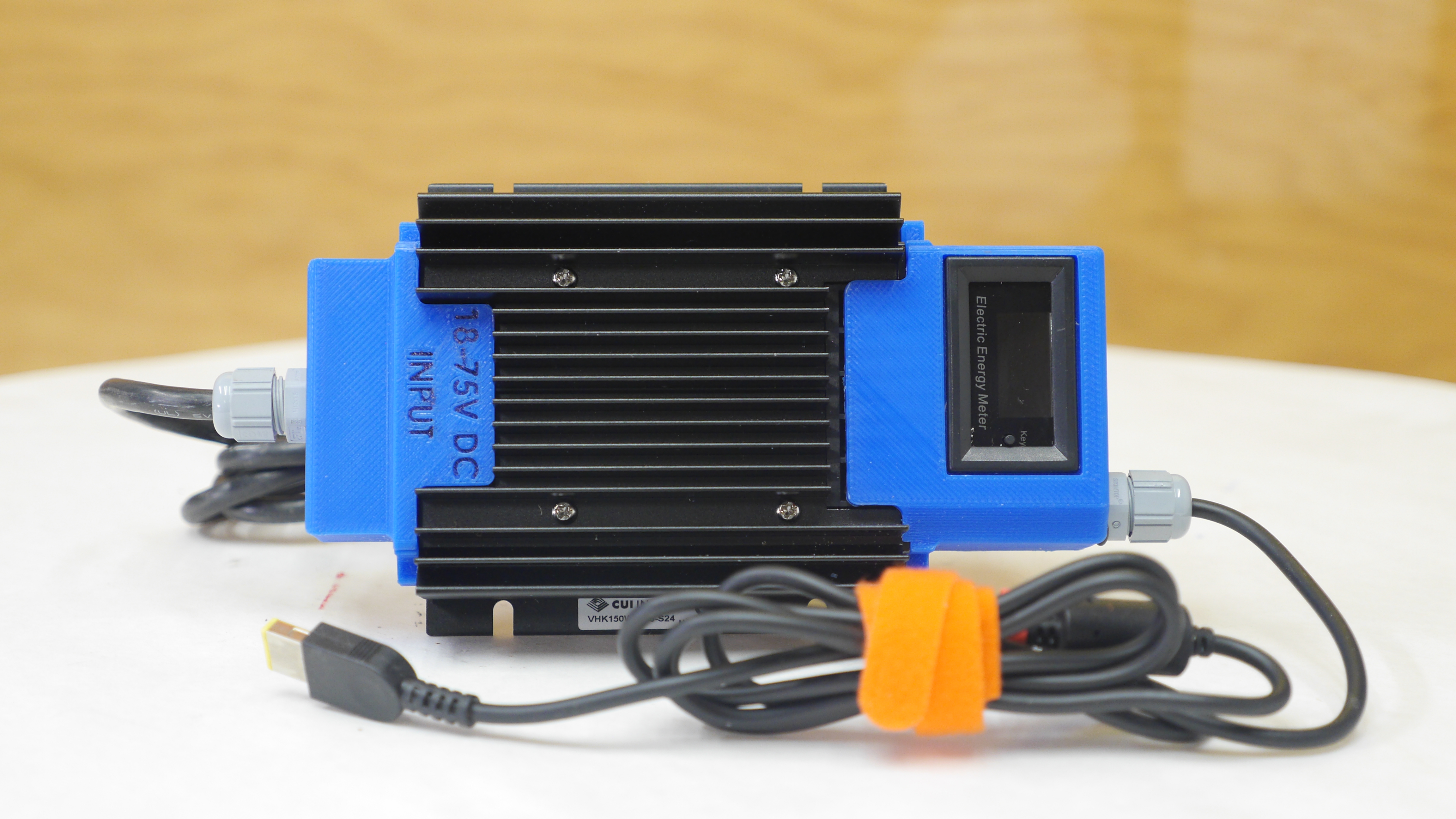
Long title, simple project:The goal here is to grab power from external battery packs of varying voltages and supply power to 'desktop replacement' sized laptops. This same topology can be used for Dell barrel jack systems. While some of these larger laptops can be powered over USB-PD, the vast majority still require a separate non-usb power brick, as the USB-PD spec only recently added 100W PD. |
The PlanAre you embracing 'working remotely' right?Picture the following:
Cycling off to your remote work spot, with a scenic vista only to be stuck with no options to top off your CAD laptop without having to lug around a power inverter and a huge pedestrian power brick. Why not skip the middleman and convert a variety of battery inputs to the standard 19-20V that most laptops crave. Lets take a look at DC/DC converters and make something compact, safe and PRODUCTIVE. 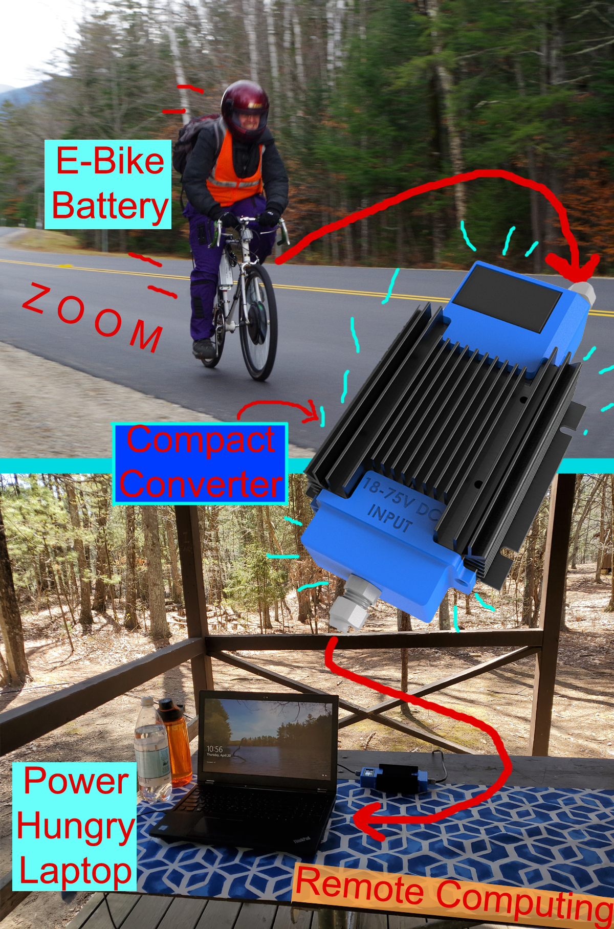
DC/DC Options
Some background, Lenovo slim-tip laptop power supplies are 20V, and the inner pin resistance to return tells the laptop what the PSU rating is. The standard PSU ratings are 90, 135, 170, 230W. I know from testing that the Lenovo P53 will run off of a 170 / 230W supply. At 170W, that's ~8.5A. We do know that this power level is not really continuous, as thermally there is not really enough surface area to radiate that much energy. 20V is not a 'stock' DC/DC output voltage, so we're going to look for something roughly 24V and find something that has an adjustable sense line for reducing the output to 20V. We also have some boundaries for input voltage, my e-bike battery is 12S LiFePO4 / 10S Li-Ion, or 36v nominal (42v max). We need it to support at least that operating envelope and ideally way outside of that envelope. So we have our requirements, +100W, 30-42v in, 20v out.
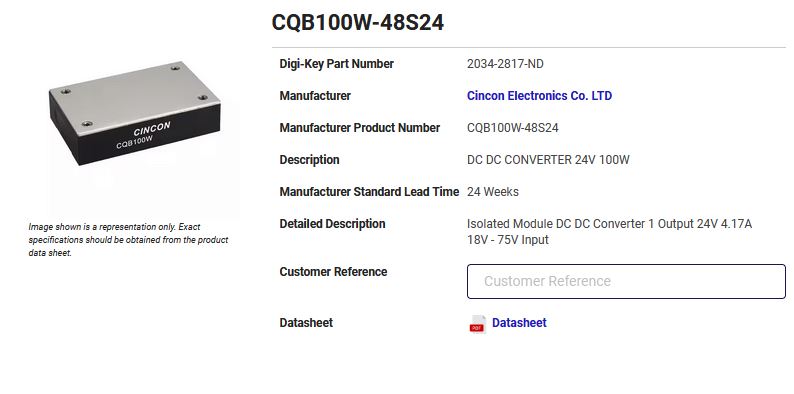
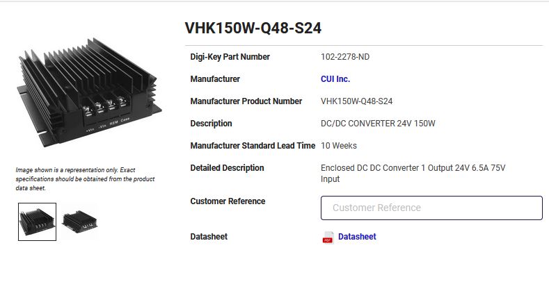
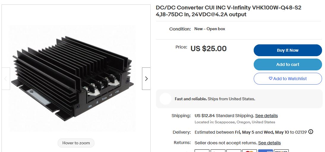
It turns out these are fairly common on the surplus market (similar one shown below), so I did a bit of e-bay haggling and got myself an 18-75V in 24V out brick. Shown below is an example of the slightly more common 12V variant, literally 6 for 65$. Another interesting one is the smaller 100W variant, which is a bit undersized but also fairly common. This may be more useful for folks who are interested in making something specific to their machine (IE; a 100W dell barrel-jack) 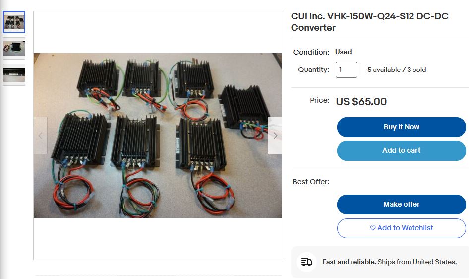
What is somewhat funny is this CUI brick does have a sibling that has a 9-36V input, this could be useful in automotive applications if your vehicle's 12V aux port was rated for it. Most aux ports are 120W max, or rather, have a 10A in-line fuse. This is actually starting to make sense, there used to be dell automotive round barrel power supplies which would connect to a cigarette lighter outlet and give you a mobile 90W on the road, but these somewhat disappeared with the advent of the larger desktop replacements. A CAD Model AppearsThis is an interactive model shown below, which should provide multiple viewpoints. The back cover panel is removed in this render to somewhat display the internal space for reference. This model uses the STEP files provided from CUI along with a mcmaster-carr model for the cable glands. It took a bit but this should also work on mobile, double tap to enable. Check it out!
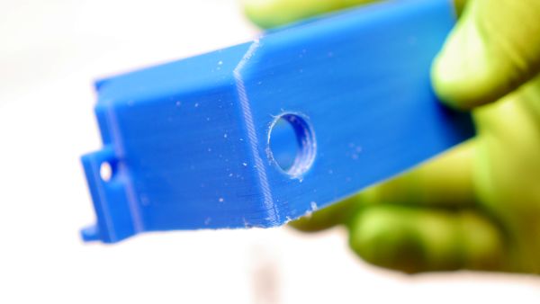
Let's start buildingWith the 3d prints complete and the supports removed we're ready to begin adding thermal inserts and the cable glands to the display holder part. I've gotta say this came out amazing. In a somewhat change of pace I used an UP! Box 3d printer which needed a bit of TLC. This is using my favorite PLA, 'Dremel' brand available on mcmaster-carr [link] It is very repeatable, prints from three years ago are the exact same hue, same materials properties, overall great. UP! software is incredibly frustrating but even the 'normal' not hyper fine output looks amazing. Next up is tapping the holes for the cable glands. I have tried printed-in-place threads here and it is remarkably difficult to get to work, so I opted for a large number of walls with a high infill and a normal machining tap. In this case this is M12, the matching thread of the cable glands.
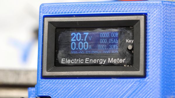
Time to add the M2.5 thermal inserts. I used a lighter to quickly heat up the brass inserts while they were attached to a screw and inserted them into their respective small mounting holes. I think on a future print I may increase the wall thickness around these spots, but they did work as is. These thermal inserts provide a 'door' for the remaining wiring to be tucked inside of. Tiny DC Watt MeterThis little watt meter is adorable, its comically tiny and available from adafruit [link], its also available on ali-express for half price [link]. It is very small and has a lot of caveats, but so far its kind of my favorite little gadget. The ratings are a bit exaggerated (150V DC, 20A), I would not run anywhere near that many volts into such a small device but for laptop voltage range it's perfect. The oled display is attached via flat flex directly soldered to the main board and its unfortunately not really constrained, so its possible to have the display slip a bit behind the bezel. 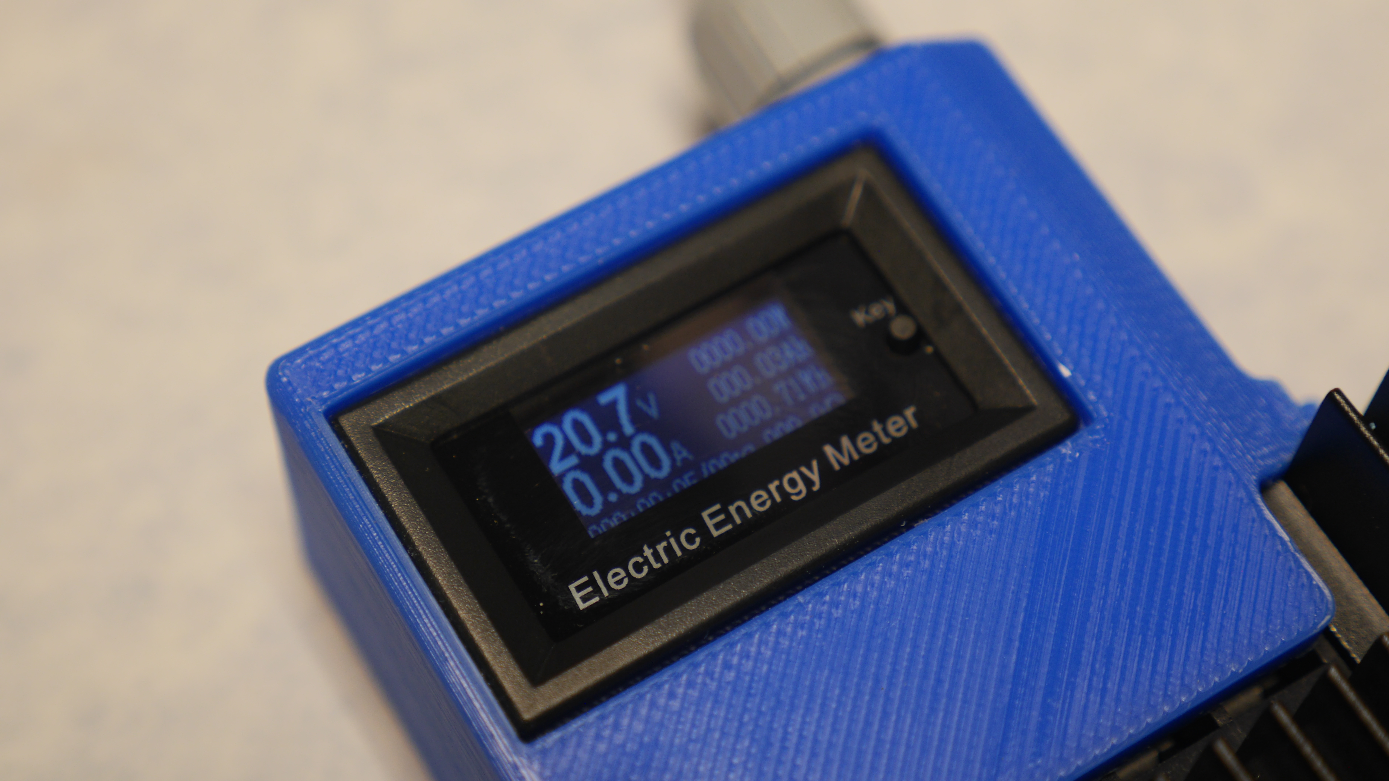
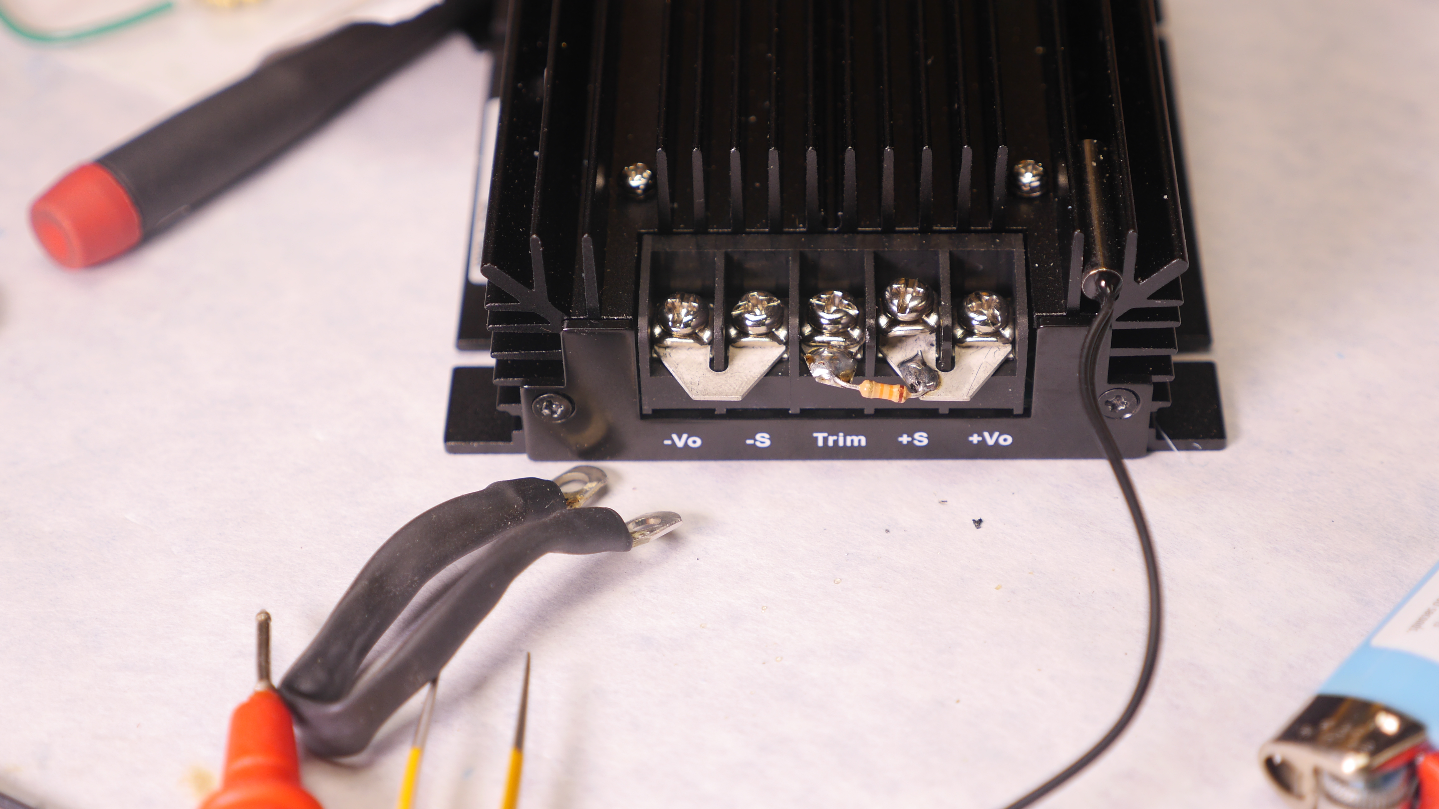
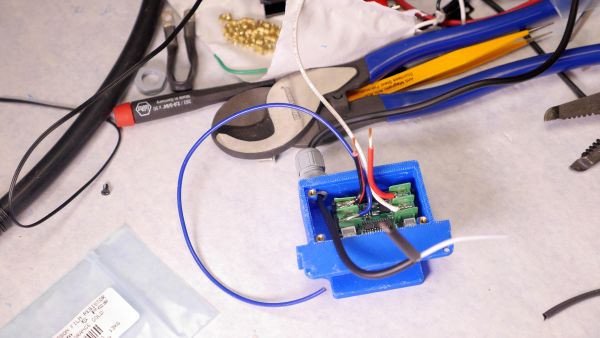
The back of the tiny watt meter is self-powered between 5-30v, so we only need to connect to the screw terminals to for power in to power out. I'm not sure what size small fork terminals fit in this thing, moreover which ones would fit and also be able to pass 20A. To get around the issues of the screws possibly falling out and the hard to find fork terminals I opted to solder input/output directly to the terminals. Filming soldering is awkward due to the camera wanting to be where I'd like to also be, so ignore some of the goofy handy work here. Adjusting the output voltageAs this is a 24V nominal supply, we do need to set the output to be ~20V nominal and to do this we actually only need one feedback resistor. I did check the stock laptop power supply and it came in at 20.4V, which was somewhat curious. Given that this is a 2-wire setup without kelvin'd sense points, maybe they knew an 8A load would drop down a few hundred mili-volt over the somewhat thin coaxial-ish cable and gave it some extra volts to compensate. Unclear. Checking against the datasheet, I came up with ~12.7k to get to 20.4V and the closest I had on hand was 13K, which would be closer to 20.8V, this is pretty reasonable. The voltage adjust is a simple resistor jumper between trim and V+. Initially I was opting for the 'possibly more legitimate' use of ring terminals and small strain relief jumper wires. That ended up being incredibly awkward, even when using a bit of RTV to provide some mechanical support inside the heat shrink. 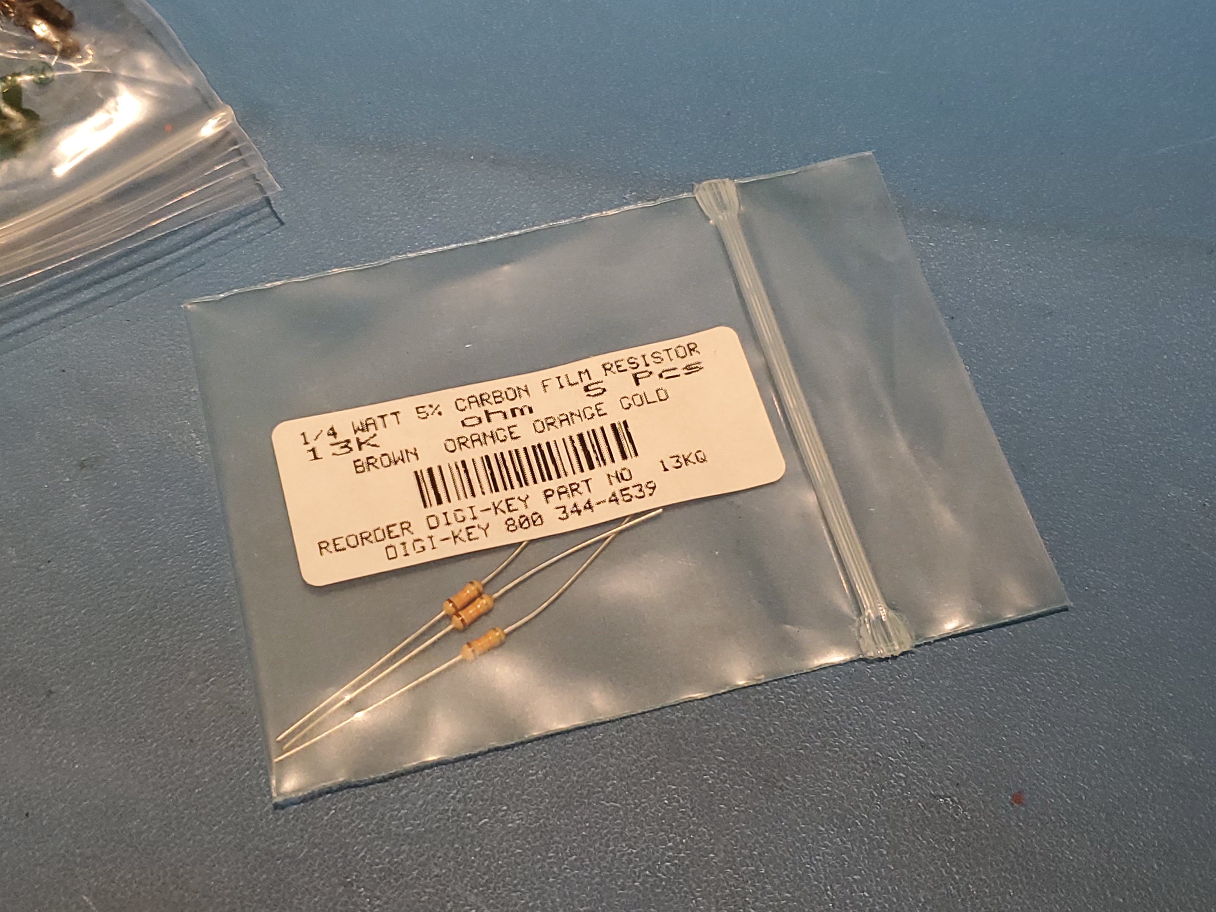
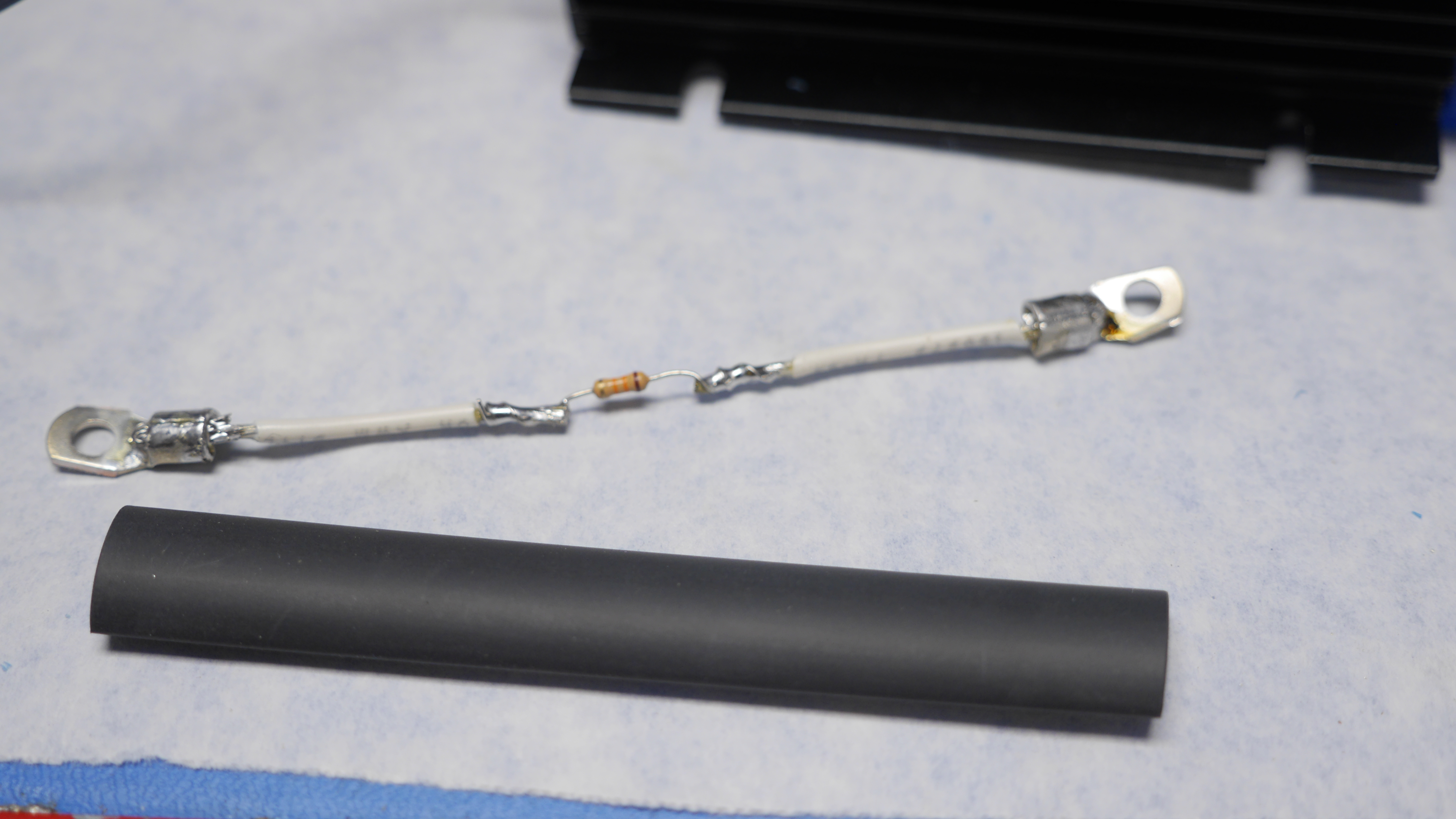
It's pretty obvious how much better the resistor just soldered to a single ring terminal is versus making a resistor-in-heat-shrink wire assembly, as shown below. The left image shows a black heat shrink loop with an embedded resistor, while the right shows the resistor sitting in-place with way less possibility of coming un-done. 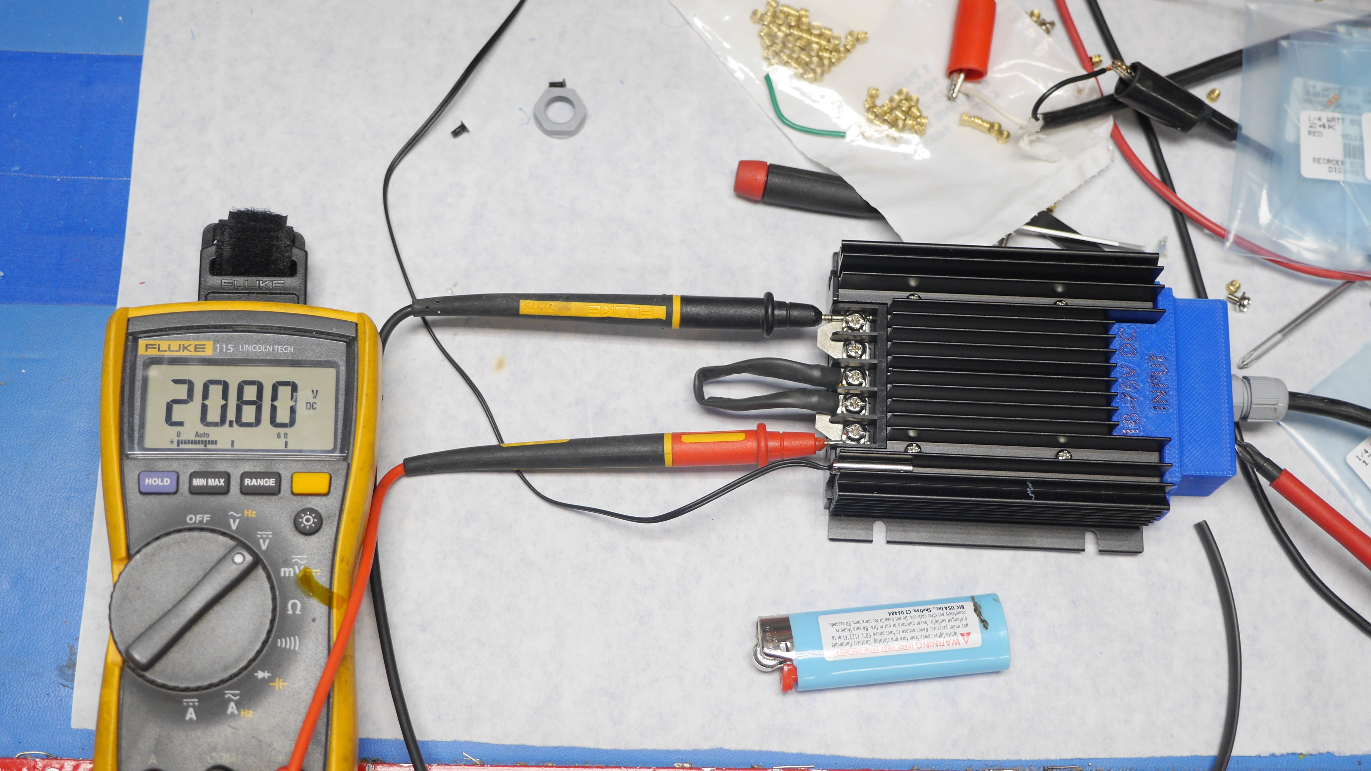
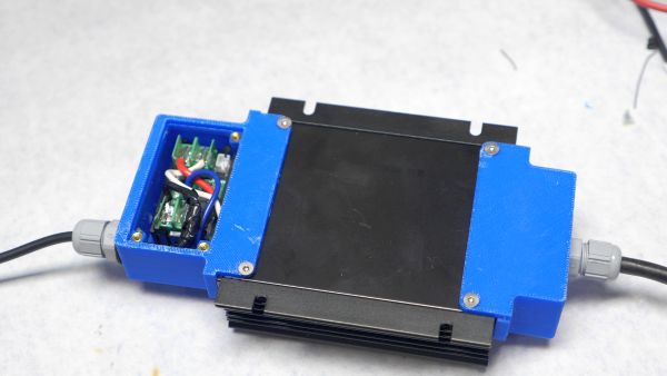
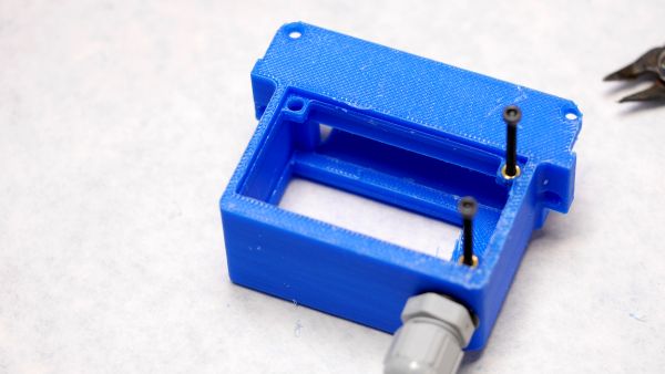
With the sense resistor set, lets finish up the output and display, shown below is an out of focus completed display module before attaching it to the DC/DC and then the remaining wiring up of the remaining wires. Speaking of, lets do a quick overview of that assembly process: At this point there's a delicate game of sliding everything together while tucking away the intermediate wiring. 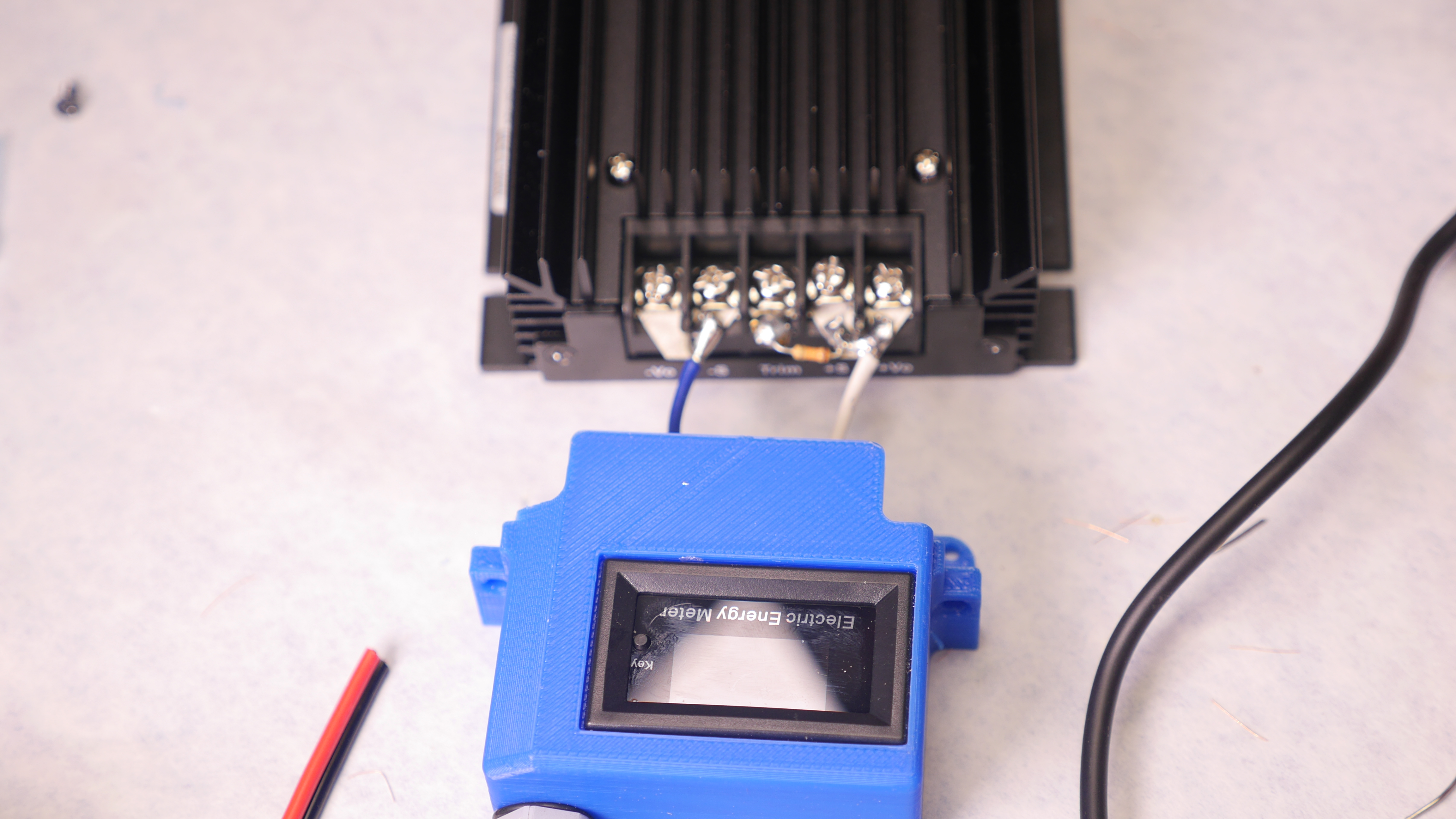
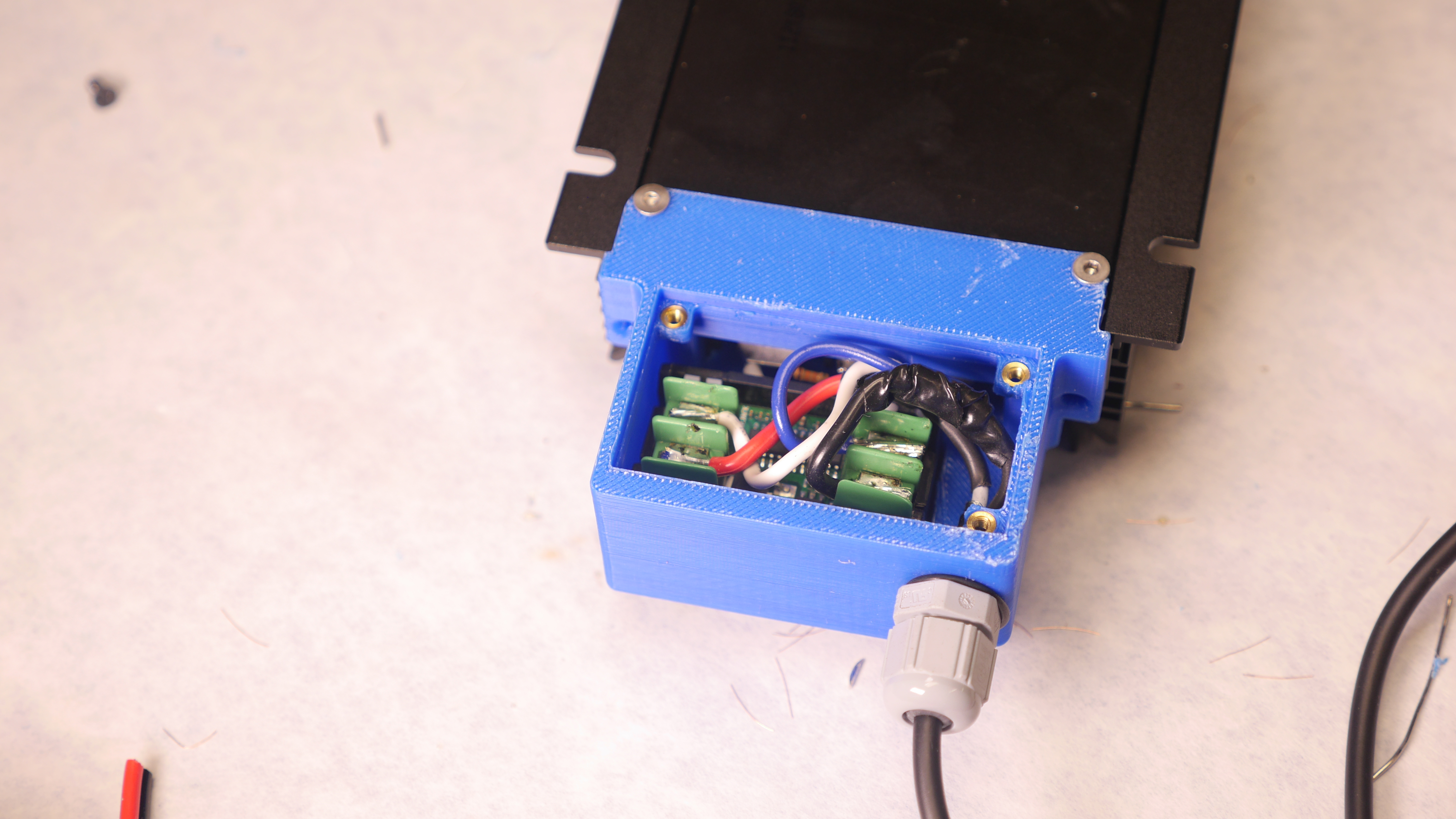
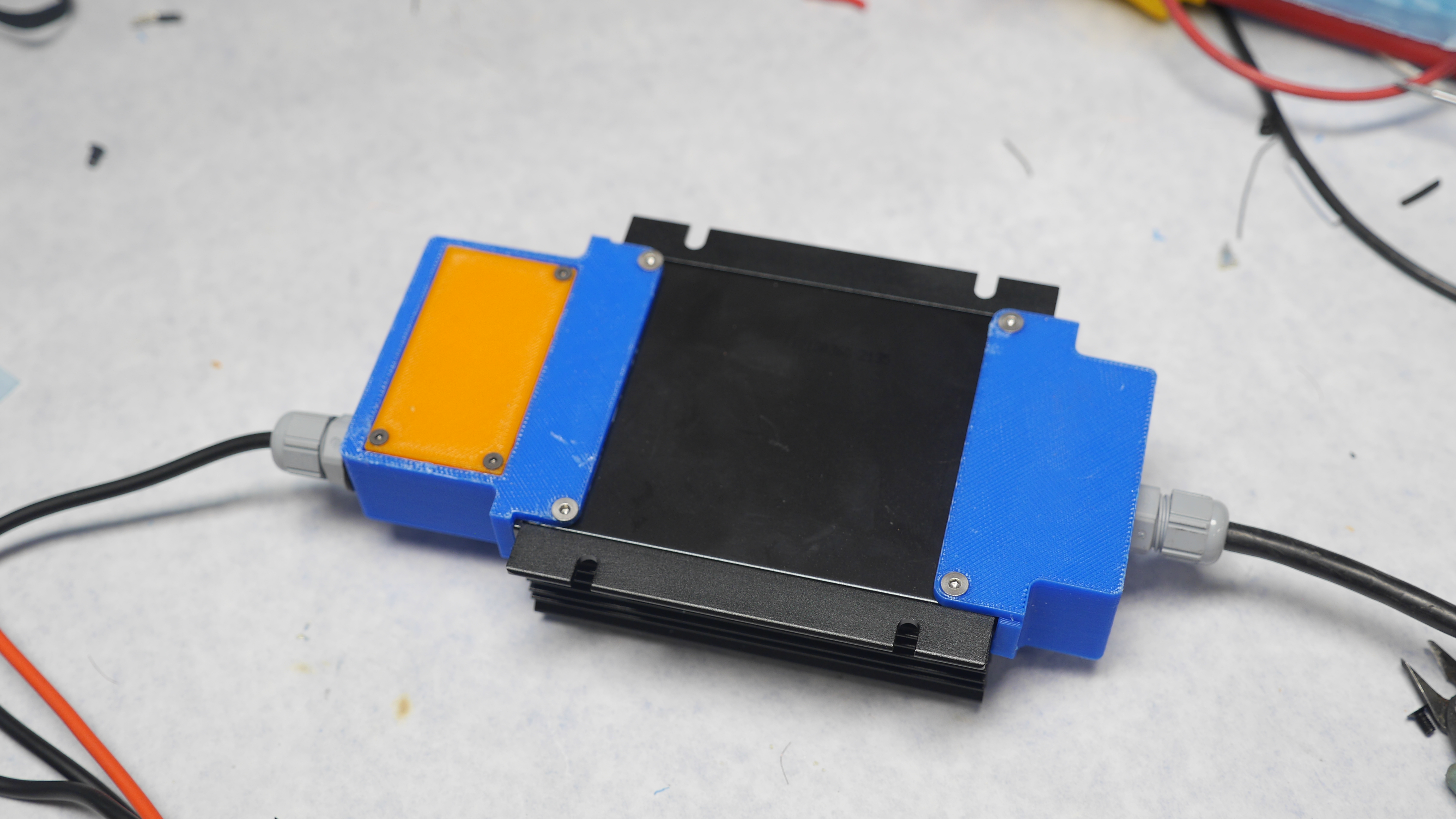
Using the existing mount-pointsThe hardware used to hold down the covers and base plate of the DC/DC is just normal M3 screws, the nice part about them not being some odd self-tapping screw is we can remove the stock screws and just add in a longer screw to compensate the difference in length due to the printed part. The only shortcoming here is verifying the screw length that enters into the case is preserved in case it interacts with anything internal. In this case I used flat head M3 x 10mm screws on the base and sides. While it was possible to just use the side facing screws, grabbing from two axes really helped in making this more structural while also reducing space for debris to find there way in to the screw terminal area. Tying everything upThe last bit was to tie up the internal wiring, and attach the back cover. I opted for orange here for the cover both for contrast and also because it was what I had queued up in the printer. 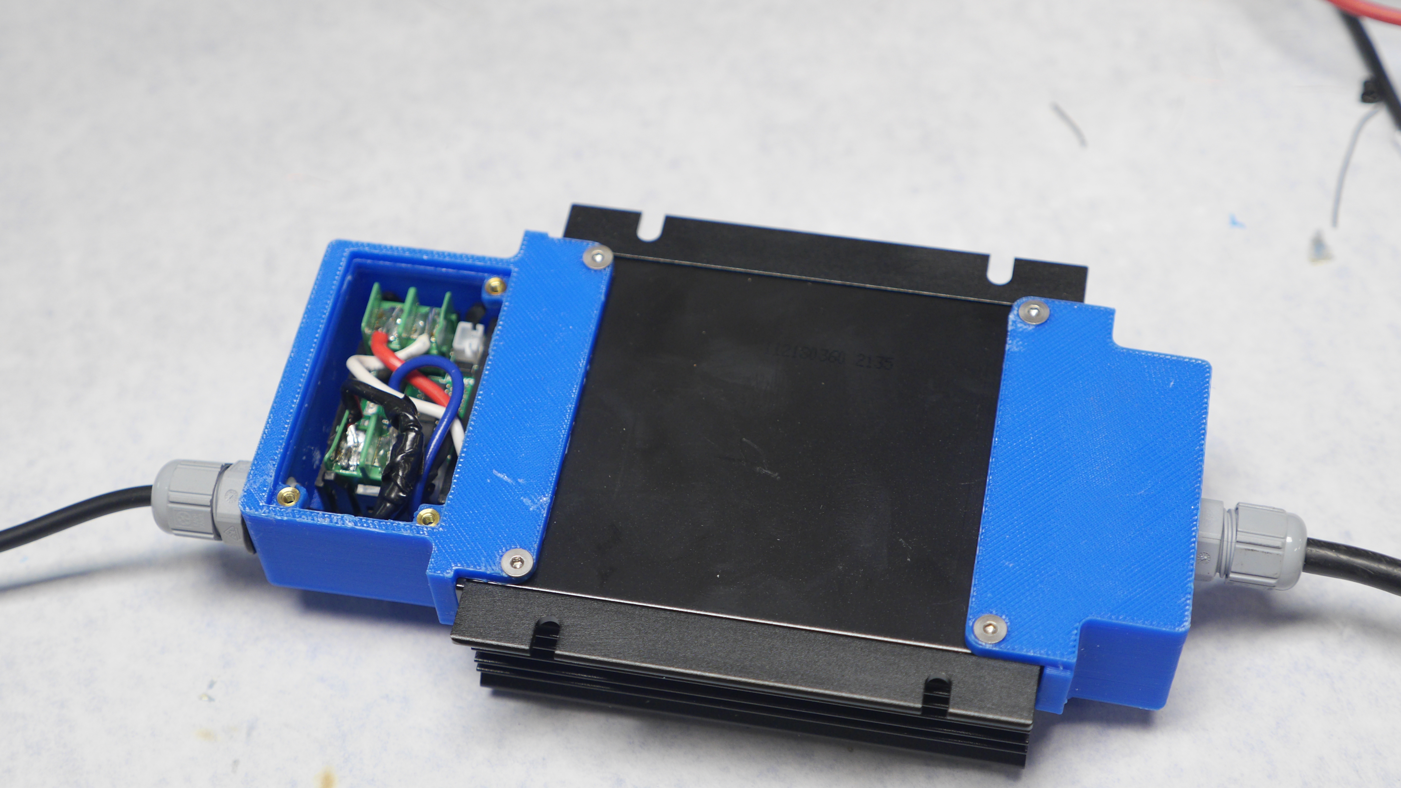
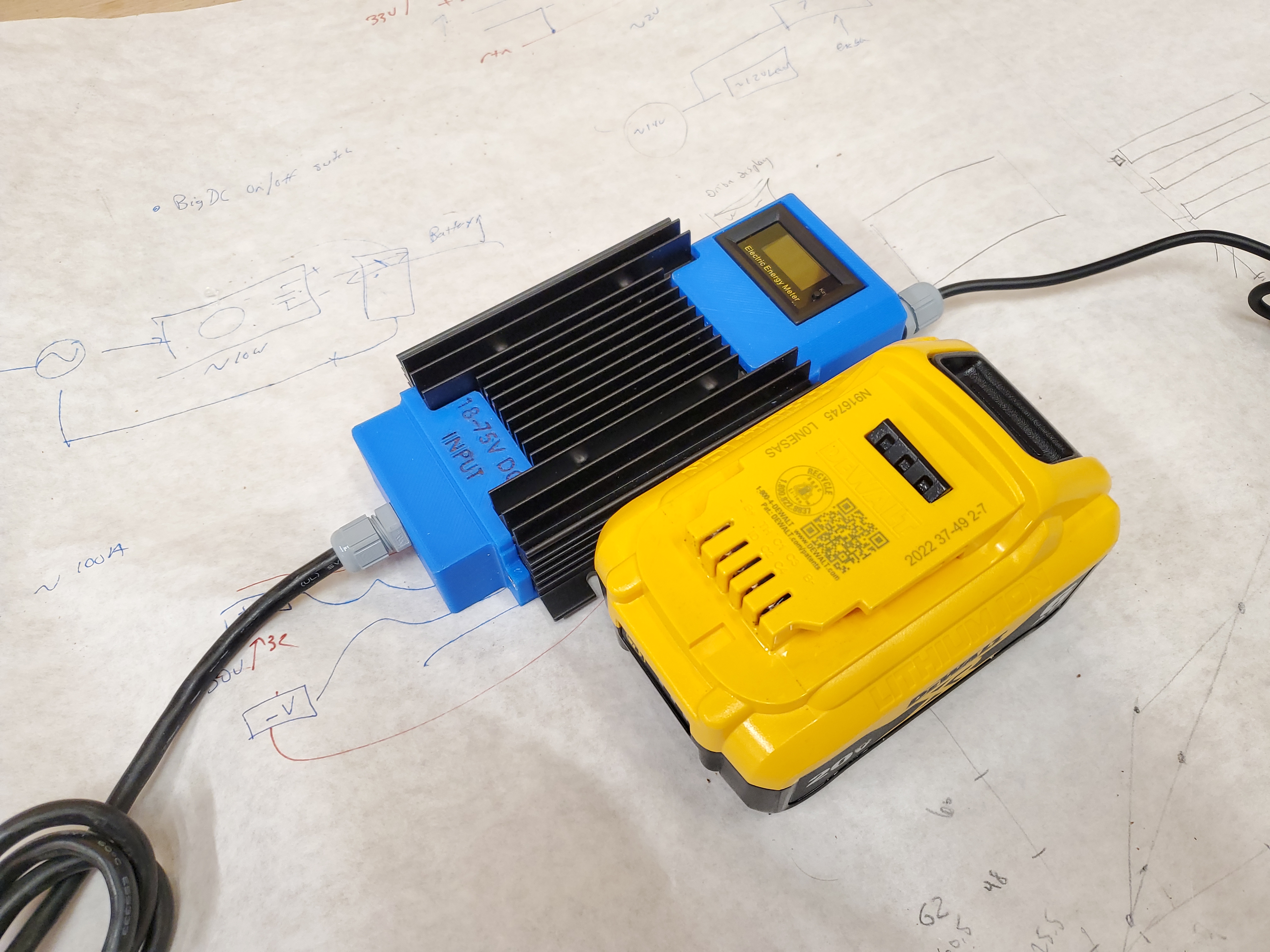
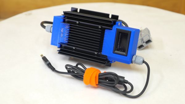
Size ComparisonWith the DC/DC prototype complete, lets take a quick comparison vs the 'stock' charger, while they are not identical power rating, they both run the P53 without any throttling. Its mechanically smaller, but the heat sink does stick above the stock charger height. After building this there's a few things I would change. It may be a bit more compact if I used recessed XT90 / XT style panel mount connectors instead of cable glands. The chassis-mount sides of the DC/DC also do not really have any benefit and can get caught in a backpack etc, I should find a way to mill those off without getting heat sink chips into the dc/dc converter mainboard. Also shown below is the supply sitting next to a 4AH DeWalt 20V battery pack. Again this is not that big. 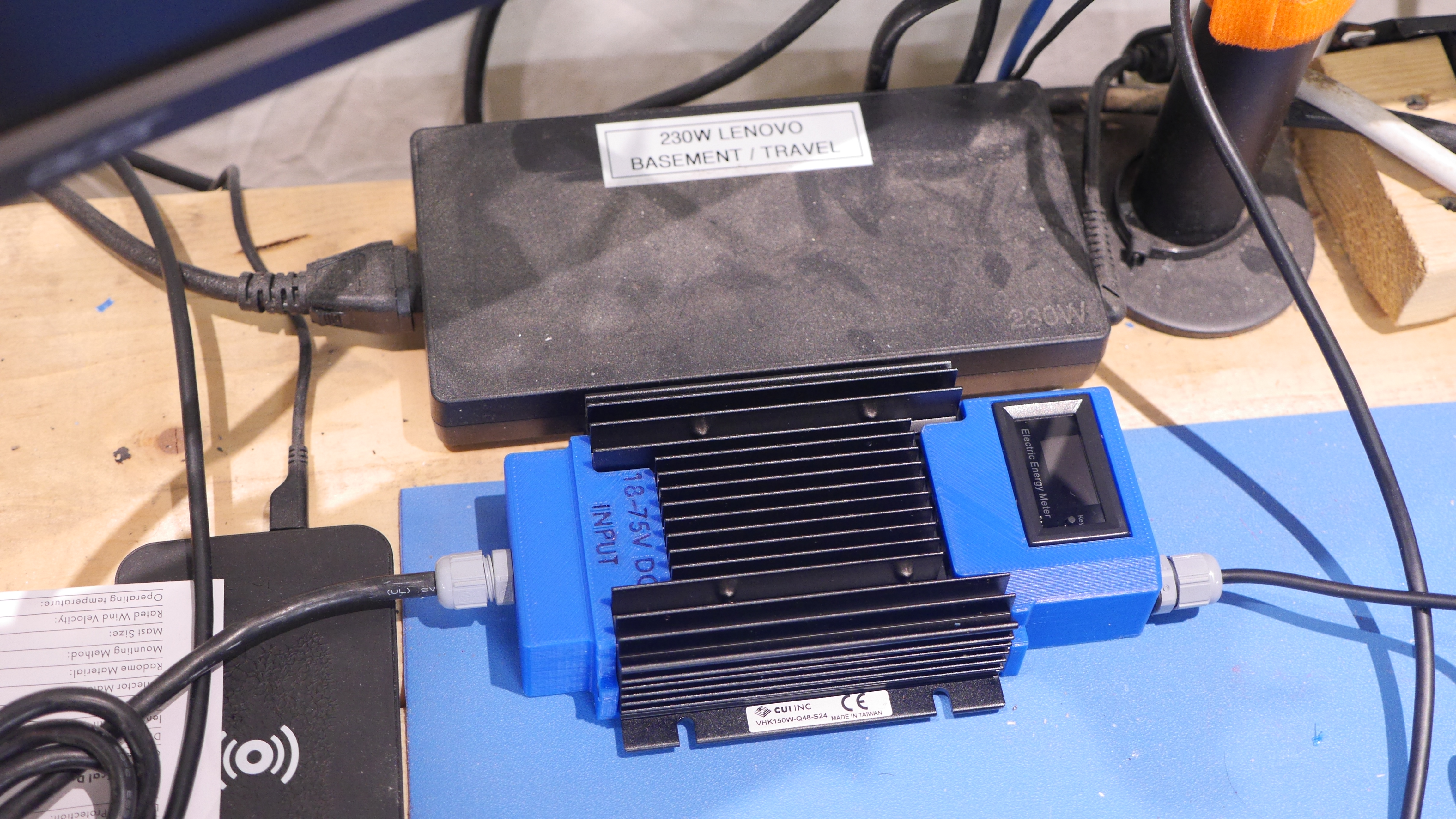
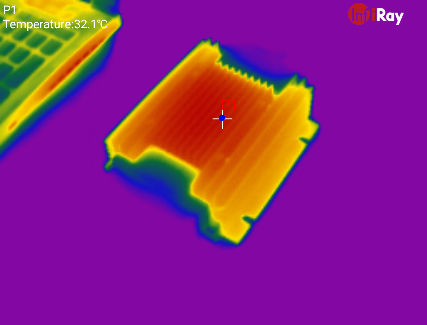
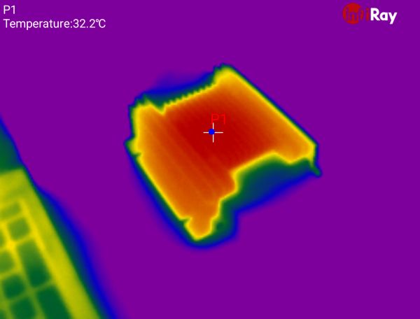
How does it handle thermally?With the supply sitting somewhat next to the laptop thermal exhaust, both charging the laptop battery and running with full brightness we see ~32C [89F] as the case temperature on the gadget. Admittedly the ambient temperature was ~16C [60F], but realistically that is phenomenal. Yes, I dragged out a thermal camera specifically to check out how well this was working, its actually really funny how the plastic covers do not even appear in the thermal image. The e-bike battery is ~400wh, so I have a few hours of continuous use to test with. After an hour of use 32C is really reasonable. The display will probably suffer at higher temperatures / in high sun, but it is really nice to know what it is doing. I find it incredibly dumb that every one of Lenovo's laptop bricks have no indication of functionality. Have you tried a 135W / 230W brick on an airplane? You're allocated ~75 watts and the only indication you have of your charger working is the mains outlet indicator probably hiding awkwardly under your seat. Seeing 20V, and current draw is overkill but also awesome, you get a way better feel for what your laptop is doing. 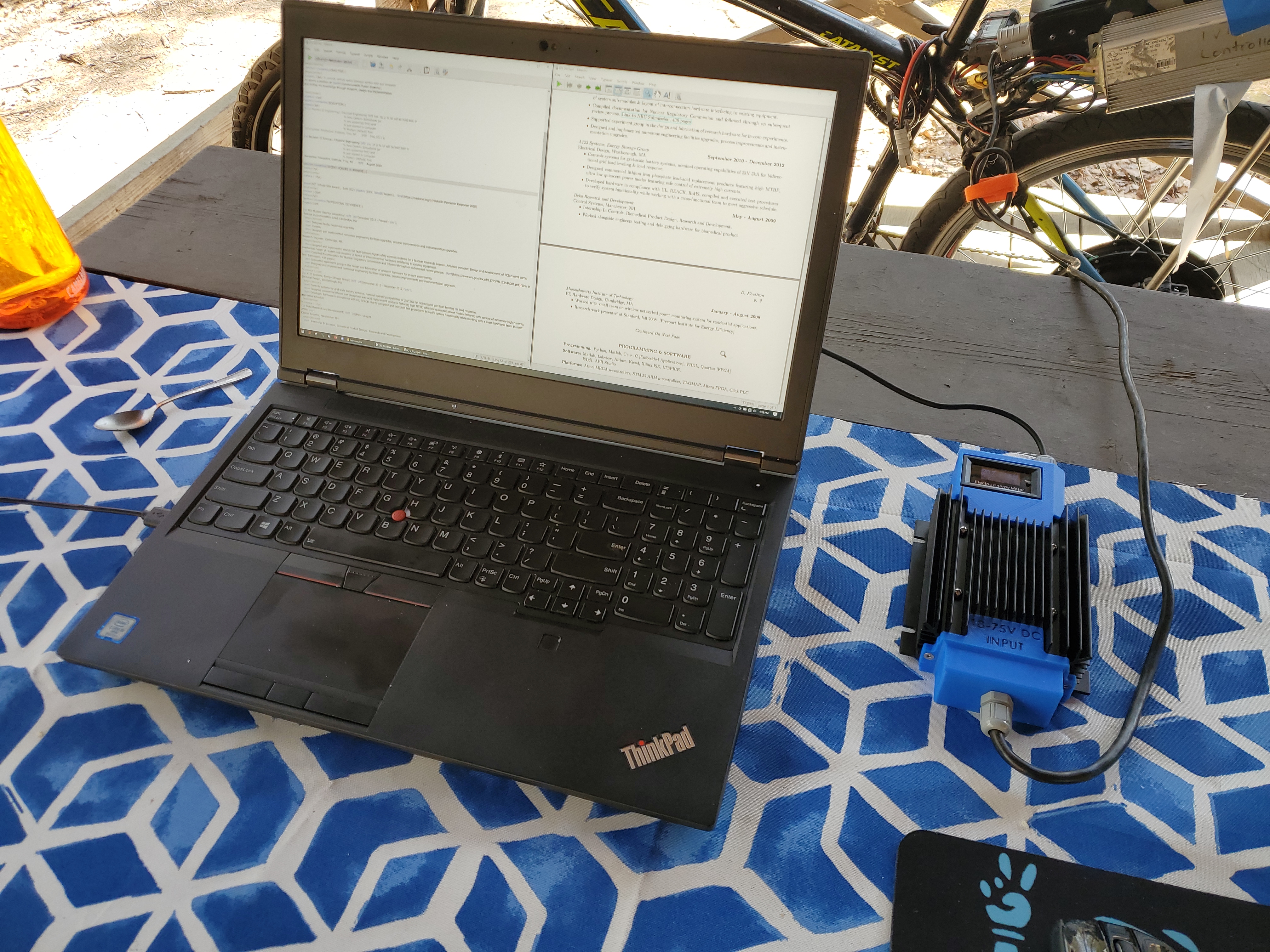
CAD & Supporting FilesWe have a few printed parts, and a few purchased parts, so lets start with a diagram and supporting files. Units shown below are imperial. 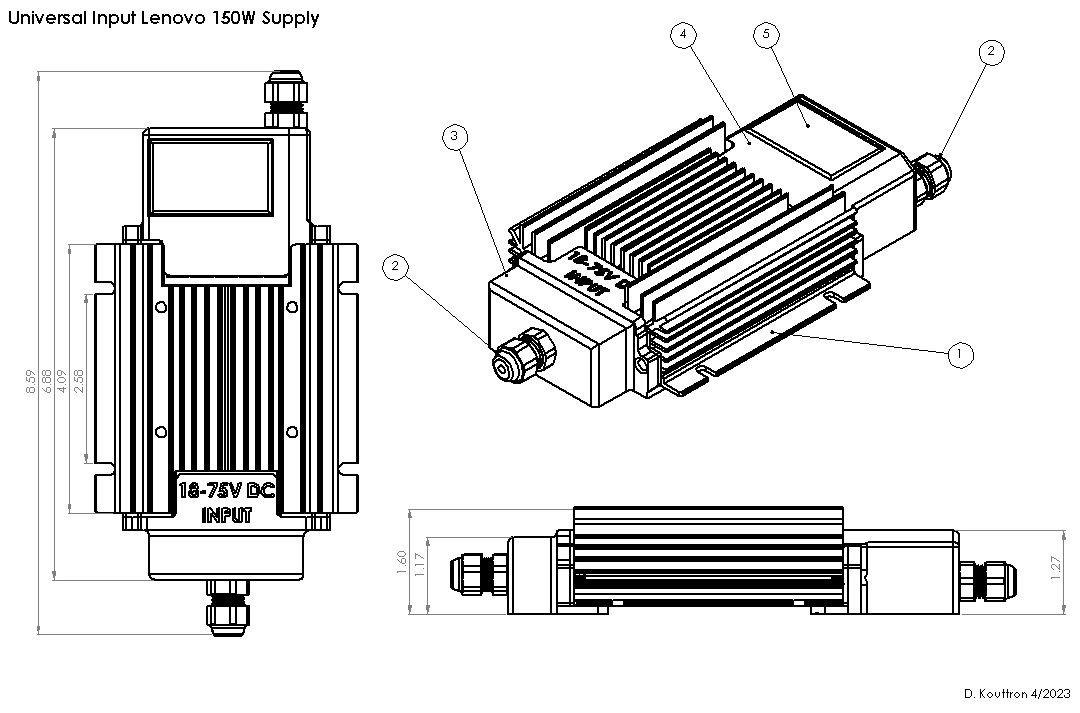
And finally, the project as a SolidWorks pack and go [link] Concluding ThoughtsThis came together in a little over a day which is really amazing. The prints all fit, I had the right size screws on-hand and the right size tap for the cable glands. It would be interesting to shrink the design a bit, either using the smaller bricks outlined earlier or changing how the cables connect to the DC/DC. I have mixed opinions about nixing the cable glands and going for panel mount connectors. One of the benefits to the flush-mounted XT connectors is size, it removes the cable gland nubs sticking out, but it does result in the 'ah dang I forgot the corresponding cable'. Having a polycarbonate cover on top of the watt-meter may also be a good idea to keep dust / outdoors from sneaking its way into the display. I think this could work with some small recessed thermal inserts and maybe a square o-ring.
|

Post your comments! |
|
Comment Box loading
|