
Dane Kouttron
This project / writeup is in progress, check back for more soon!
Waking up a recycled DC Fast ChargerCan I restore a Gen-1 DC Fast (CCS) charger?DC Fast charging is still fairly new, with the first generation chargers coming into existence in early 2014. The first generation DC Fast chargers are somewhat huge, with their modern counterparts fitting nearly three times the power density in the same form factor. SAE J1772-2017 is the nominal specification for DC Fast charging up until the transition to NACS, or SAE J3400.The following details attempts waking up this monster power supply. |
||
The Plan: Develop CCS hardware interface for DIY use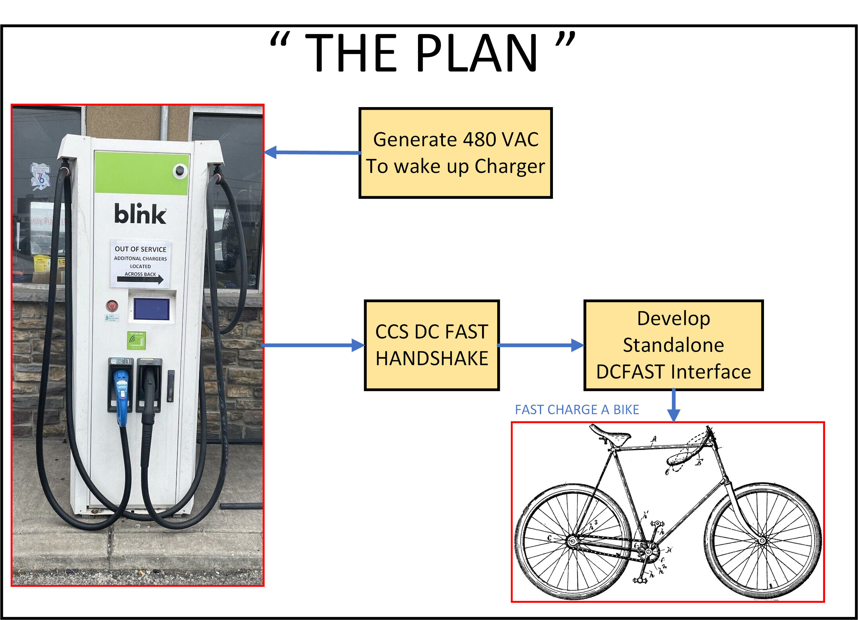
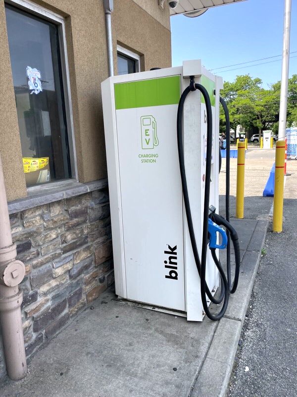
The plan is fairly simple. Its wintertime in the northeast, I've been interested in adapting some of the Dane robots to adopt CCS / external DC charging, however documentation on the implementation of the higher level communications is sketchy at best. I'd like to implement an opensource hardware solution to permit use of the lower voltages available on some of the CCS chargers. Early chargers can charge down to 50V (or 48V nominal batteries). This is well within the realm of electric bicycles or golf carts, let alone snow eating robots. But its hard to test hardware without something to talk to. There are some Keyence test fixtures, but they are expensive. At the time of writing there are no 'consumer' sized CCS fast chargers for home, as generally 'homes' do not have a spare 50+ kw sitting around. So lets go find something to talk to. An introduction to the finest of New Jersey EV ChargingI've been keeping an eye out for surplus or broken CCS compatible chargers. Nearly every time the sale did not go through, or the vendor would "sell" the device off platform. Finally I found one, it was not working or easy to transport but it was somewhat feasible to acquire. 
My plan was simple, rent a lift-gate-truck, use its magical elevator powers to lift the heavy monster and then use it to unload it. Man that was a great plan. Unfortunately my reservation at truck land did not go well. This was not the fault of the guys down at this branch, for whatever reason Budget Corporate sent me on a goose chase. Either way my plot for just paying for a truck was out the window. 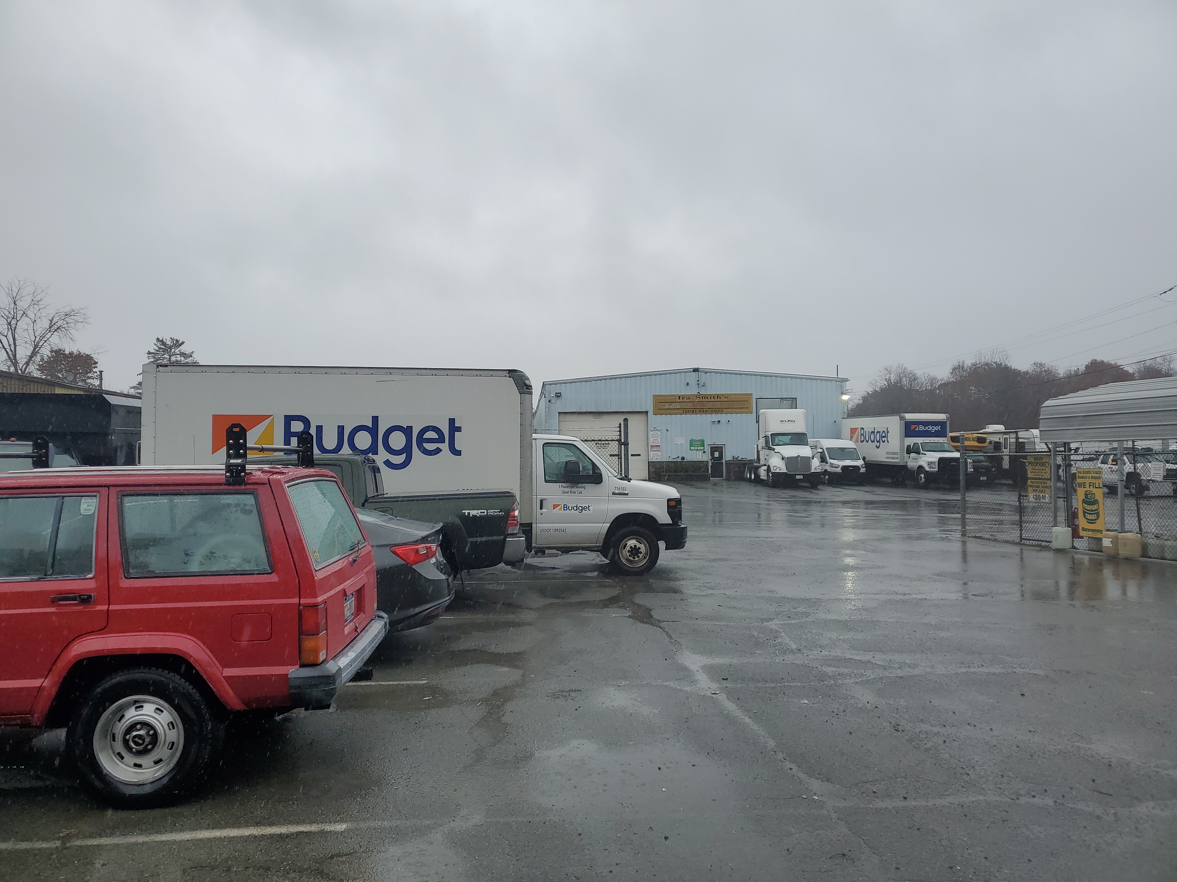

With the day shot as I had already scheduled the vendor to be available for pickup and loading and driven to the location to get the truck, I scurried back and decided to find an alternate vehicle.
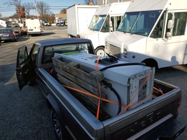
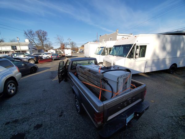
Technically speaking, the charger could sit in a pickup truck bed, not a modern pickup truck as generally the cargo area is relatively small while the vehicle is comically large, modern pickup beds are like 4ft-ish.
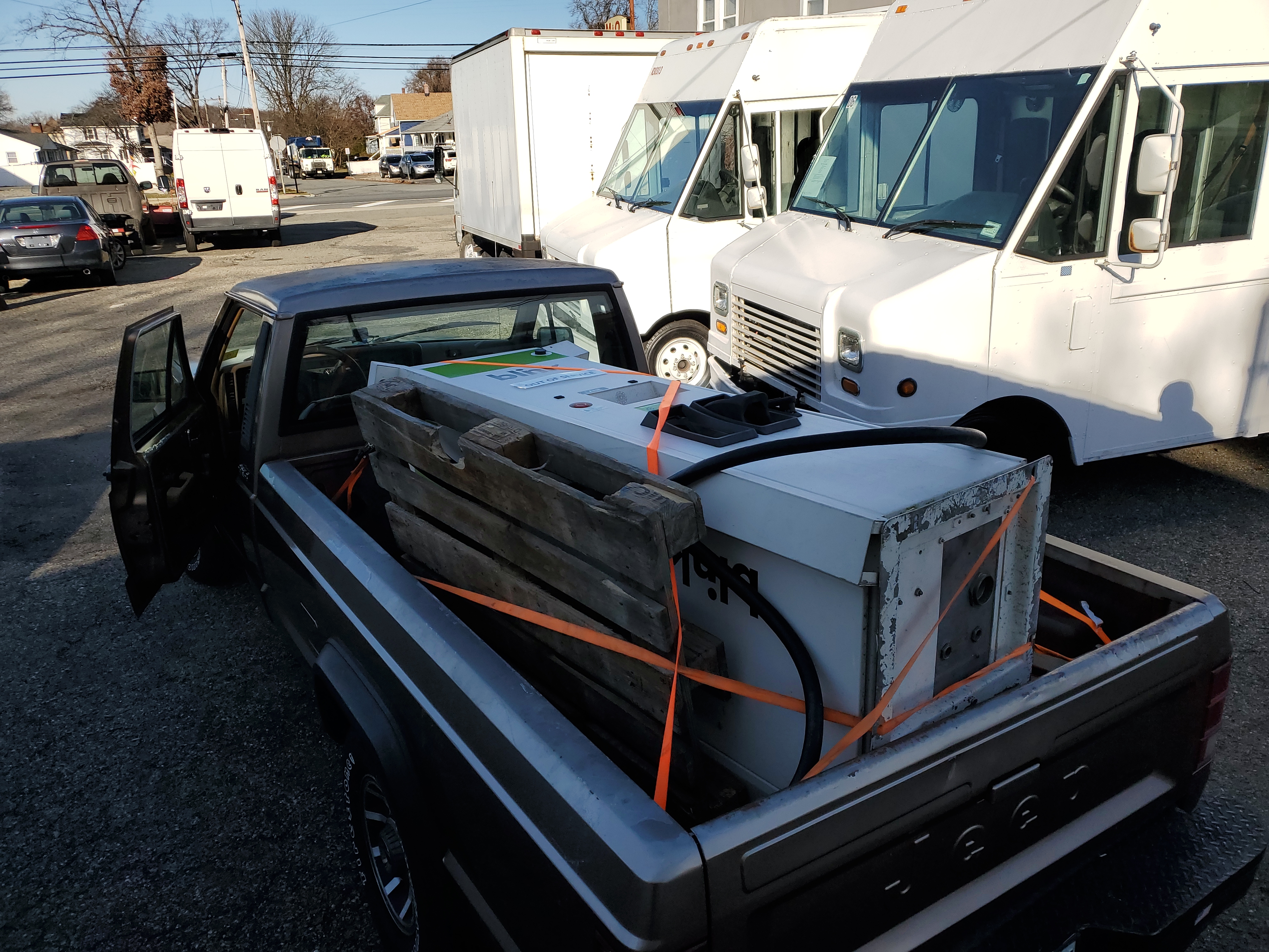
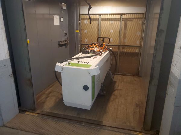
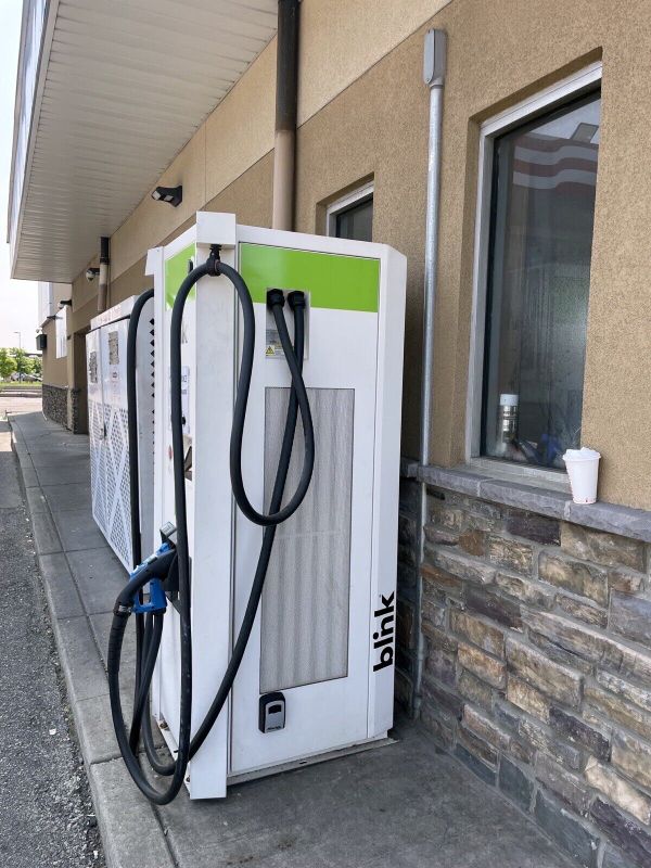
With the gadget loaded up, I was off on a 250 mile journey from NJ to MA, and then the quest of unloading the heavy rectangle out of a pickup truck. Finally, after getting it out of a pickup and onto a pallet jack, with lots of pulling and pushing, I got it it moved into the workshop. This is actually the first opportunity to open the charger and verify that it was actually a charger. In retrospect it probably would have been a great idea to verify the insides were not a charred mess when i was in New Jersey. Ah well, lets take a look at what is inside the front cover. Did I mention that this thing is heavy. 
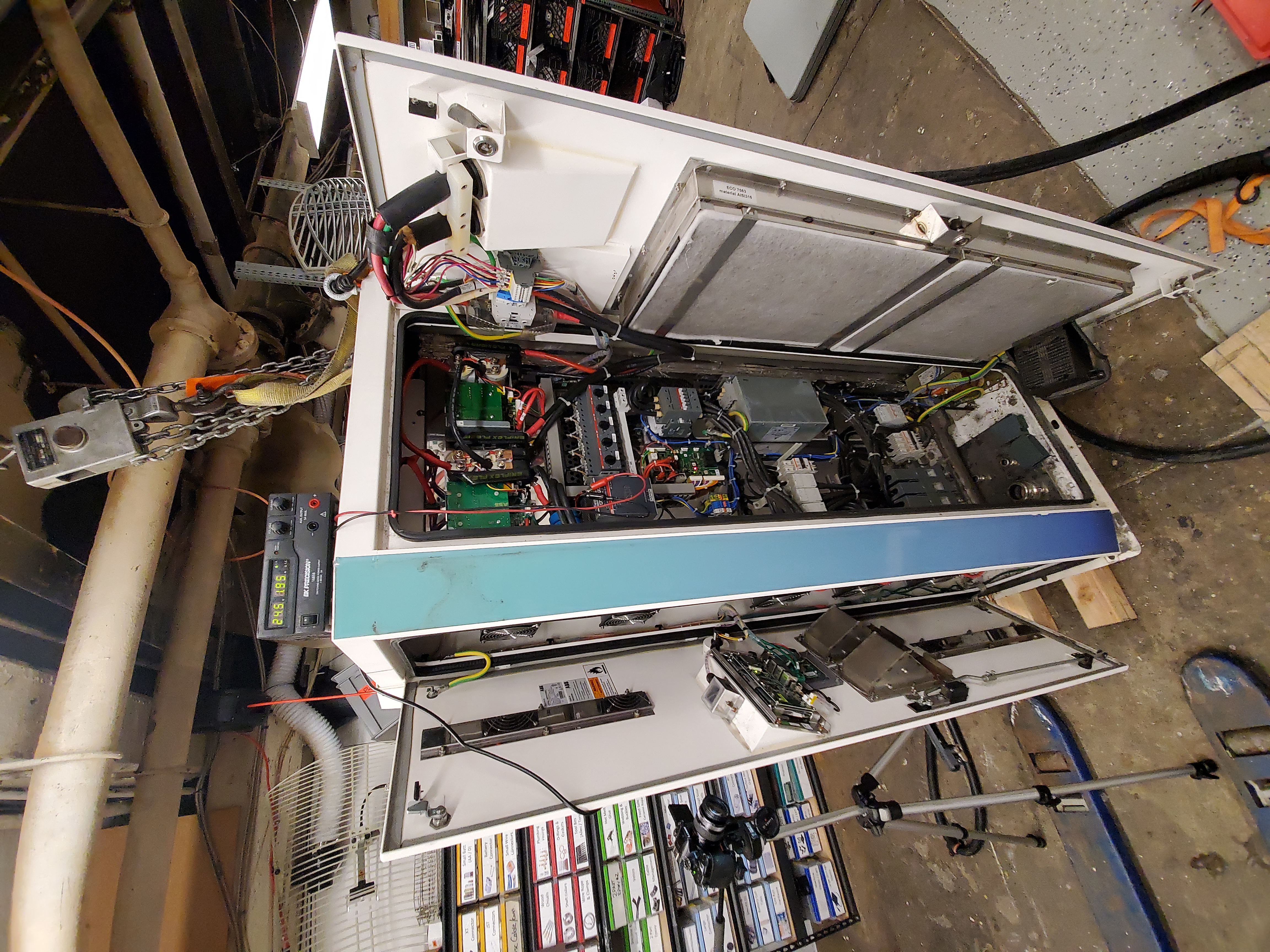
Inside the front cover we find a relatively small interface board that's likely responsible for HMI as well as commanding the large switch-mode supplies in the main cabinet. 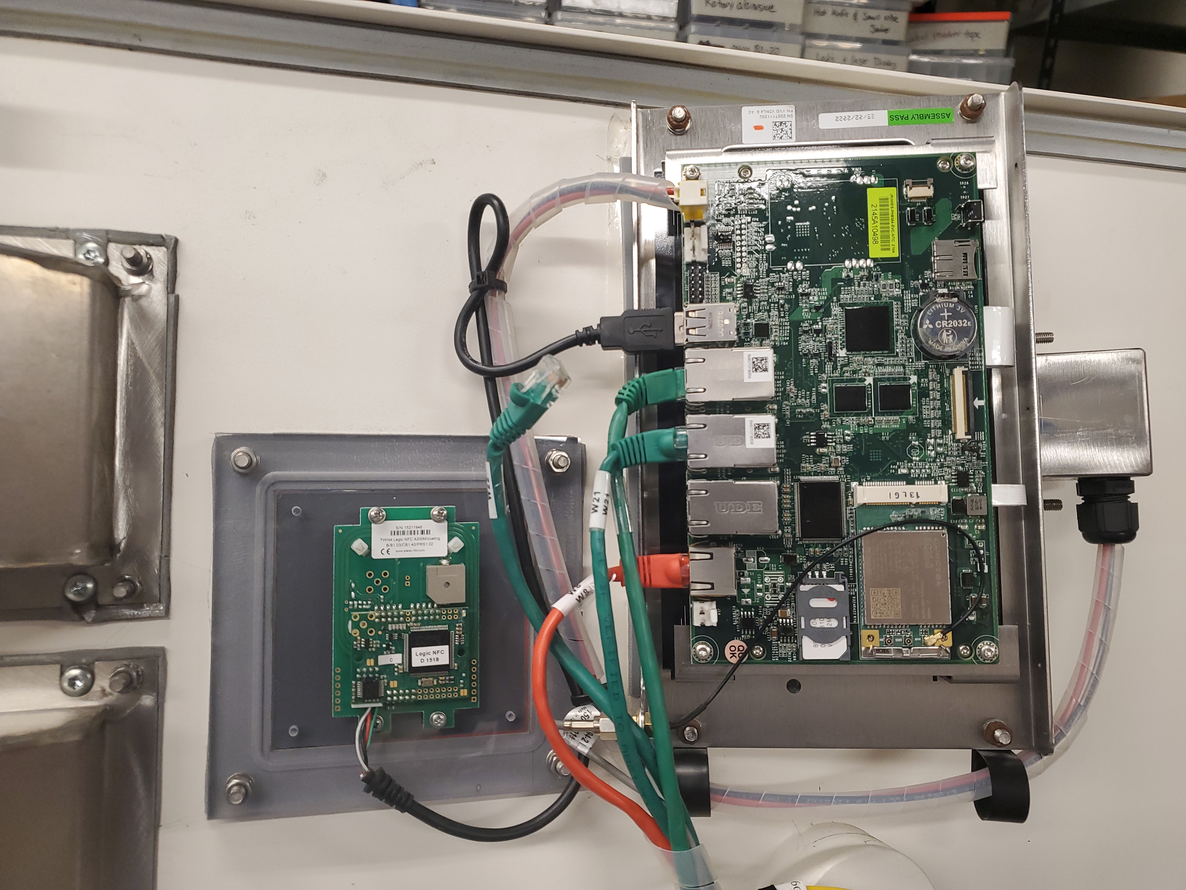
The control computer seems to be a custom arm board with five CAT5 connections, some USB ports, a mini PCI slot for a modem and some GPIO for interfacing with the outside world. The actual 'modem' is a mini PCIE board that uses an EG25-G modem with an external antenna. From the manual below, we find that the ABB hardware uses a 2G / 3G modem for telemetry. Lets find out some more information about the modem to figure out if this was actually only 2G/3G, and the possible cause for why this thing was offline. 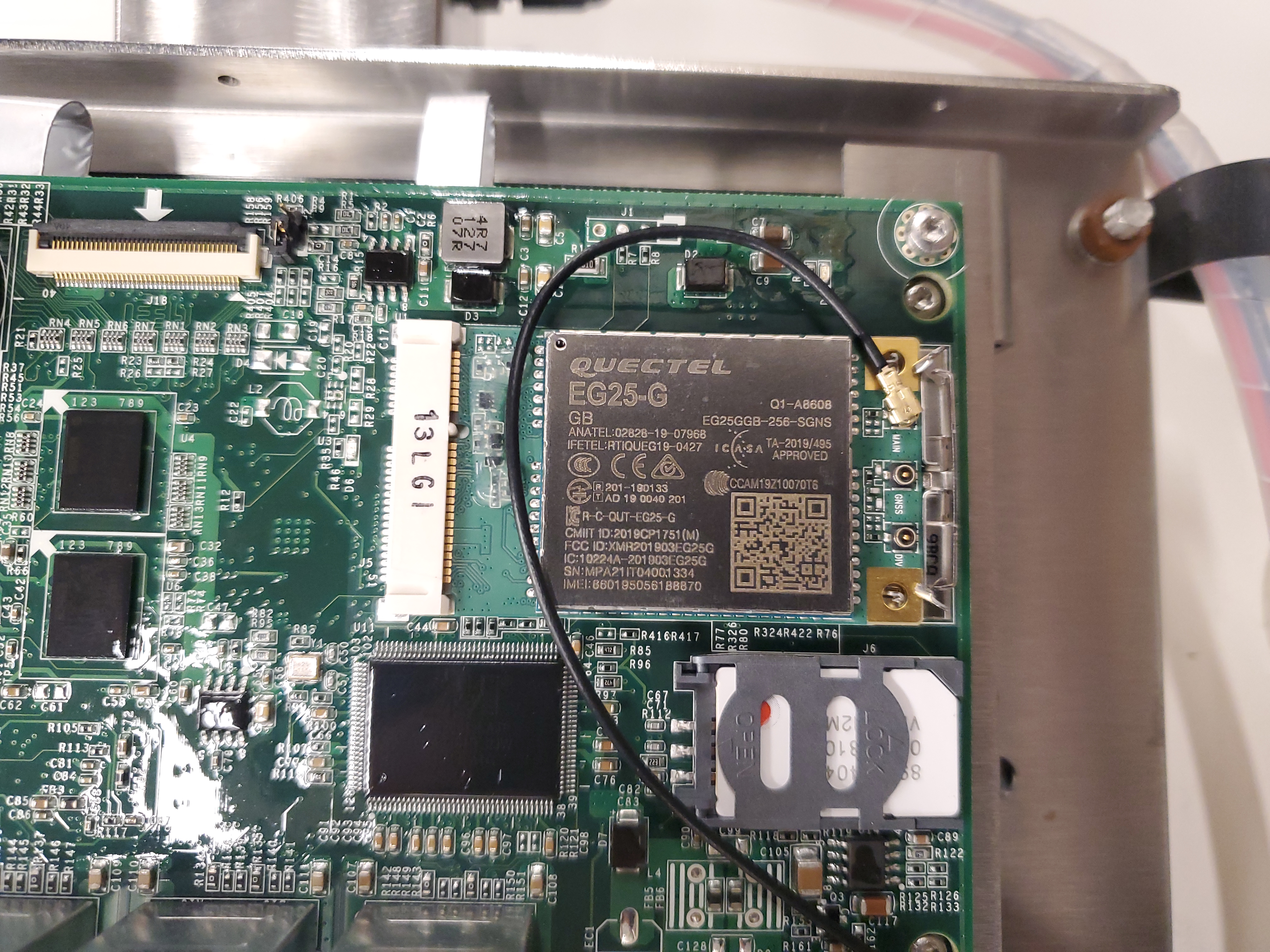
The PCIE card is still available on Digikey [link]. Lets dig thru the manual [link] and a local copy if its no longer online: [local copy]. Curiously this modem supports 4G data, its not clear if the sim card is 4G capable but it looks like the modem may not have been the issue. Is there a user manual for this thing?Here's everything I could find online / offline about the charger, all collected in the same place:
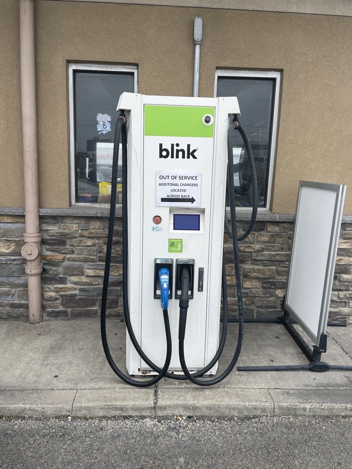
Review of technical information available:The BLINK! charger is actually a skinned charger by ABB. This model is a TERRA 53, here's a link to a short, 33 page user manual [link]. Lets see what we can learn about our friendly fridge sized power supply. There's not a lot of technical details in this 'user guide', but we do get an overview drawing giving an overview of where the charger distributes its hardware. I was somewhat surprised, this 50KW supply wants a 480V 3-phase 125A breaker. That is a relatively huge interconnect, its wild to see something this power hungry that a normal consumer an just use 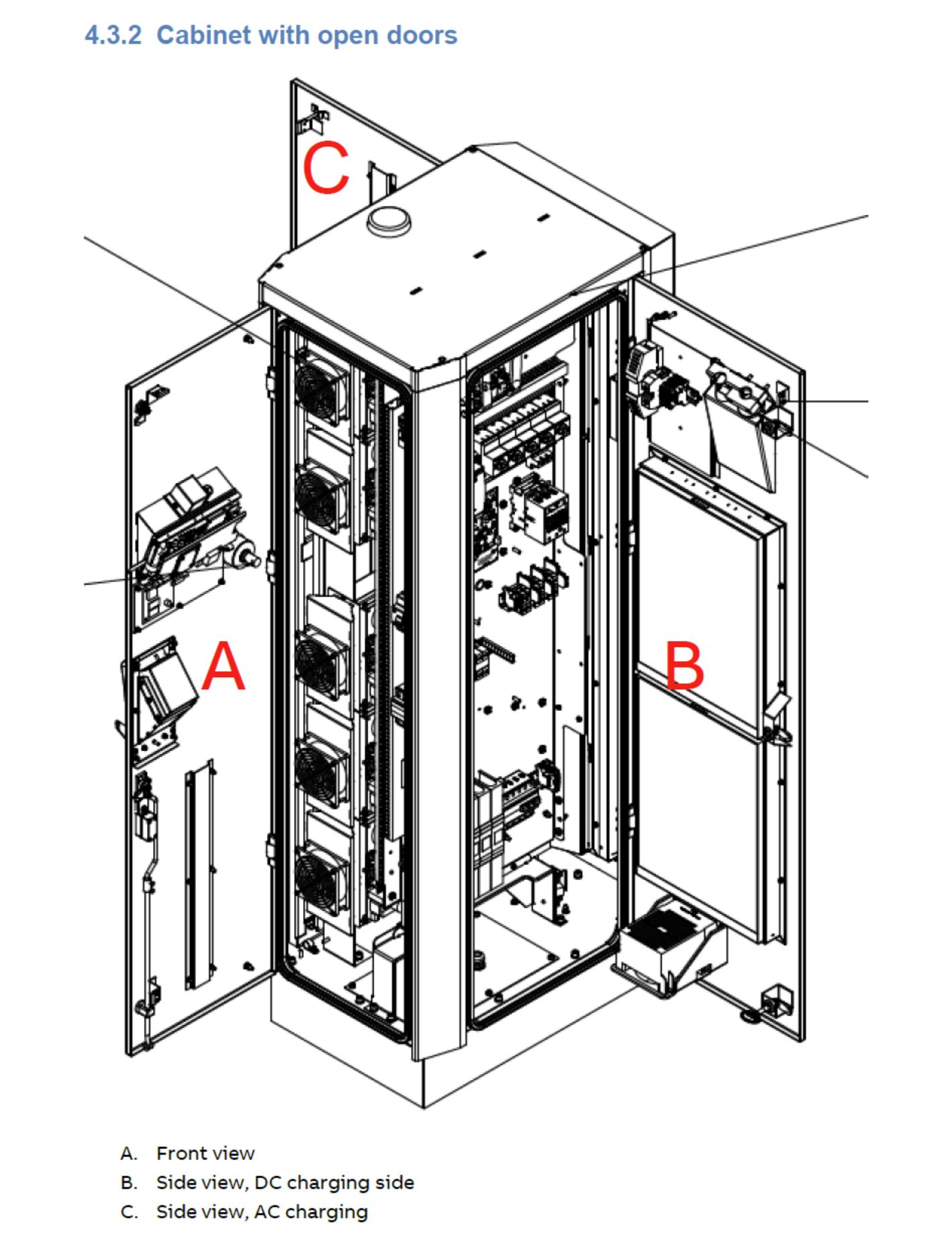
Oddly, the terra 53 has very little documentation on [ABB's website] but it has a neighboring product which seems to be nearly identical, the Terra 54. The Terra 53 can push 50-500V while the Terra 54 is a 200-500V device. We do learn what the Terra 54 needs for network access on page 20 of its manual. It prefers to use a 2G/3G modem, which is really interesting as, stateside, 3G is depreciated. Maybe this thing was put out to pasture because of a depreciated cell phone network? Otherwise this monster will gladly use CAT5 Ethernet, and wants 128kb/s up and 4MB/s down. Odd how asymmetric that is, 4MB/S per charger is not huge but, it is odd. Oh god its for advertisements, it has to be for advertising on the front panel display. Maybe its just for firmware updates, why would speed be needed for firmware updates it has ages to grab the update file? 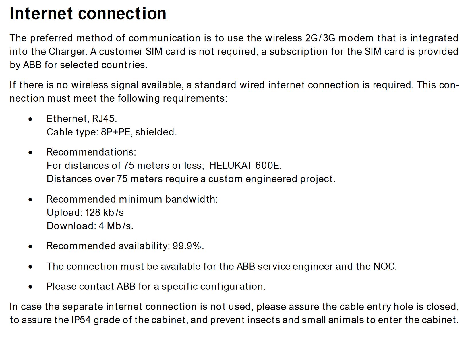
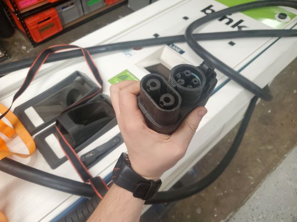
There's a good overview diagram of the full system, included in the Terra 53 installation manual. There's three actual options on this charger, and as a result multiple model numbers. The options are AC charging (normal J1772) DC charging (CCS) and other DC charging (CHADEMO). The AC charging looks odd in this diargam as the AC ev connection is generally single phase 220, not single phase 480. I'm more interested in CCS charging. Both the CCS and CHadeMO connections use the same DC link, which is not surprising as the non-used output is electrically isolated. I do like the central 24V supply for logic power, which is a good first point to start for diagnostics. 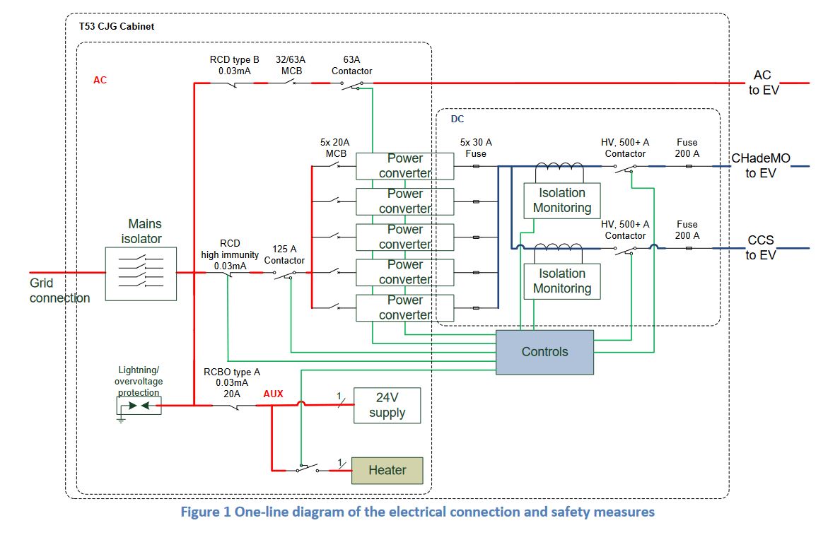
Either way, I need to move this thing, and while i can put a chain hoist in the ceiling, it is super awkward to move. The Terra 54 manual shows M10 holes on the top for lifting, its odd that only two are required, as there are four lift points. I grabbed some M10 hoist loops from mcmaster-carr and got ready to right the beast. My hoist is rated for 1.5k lbs so this should be fine to re-orient. 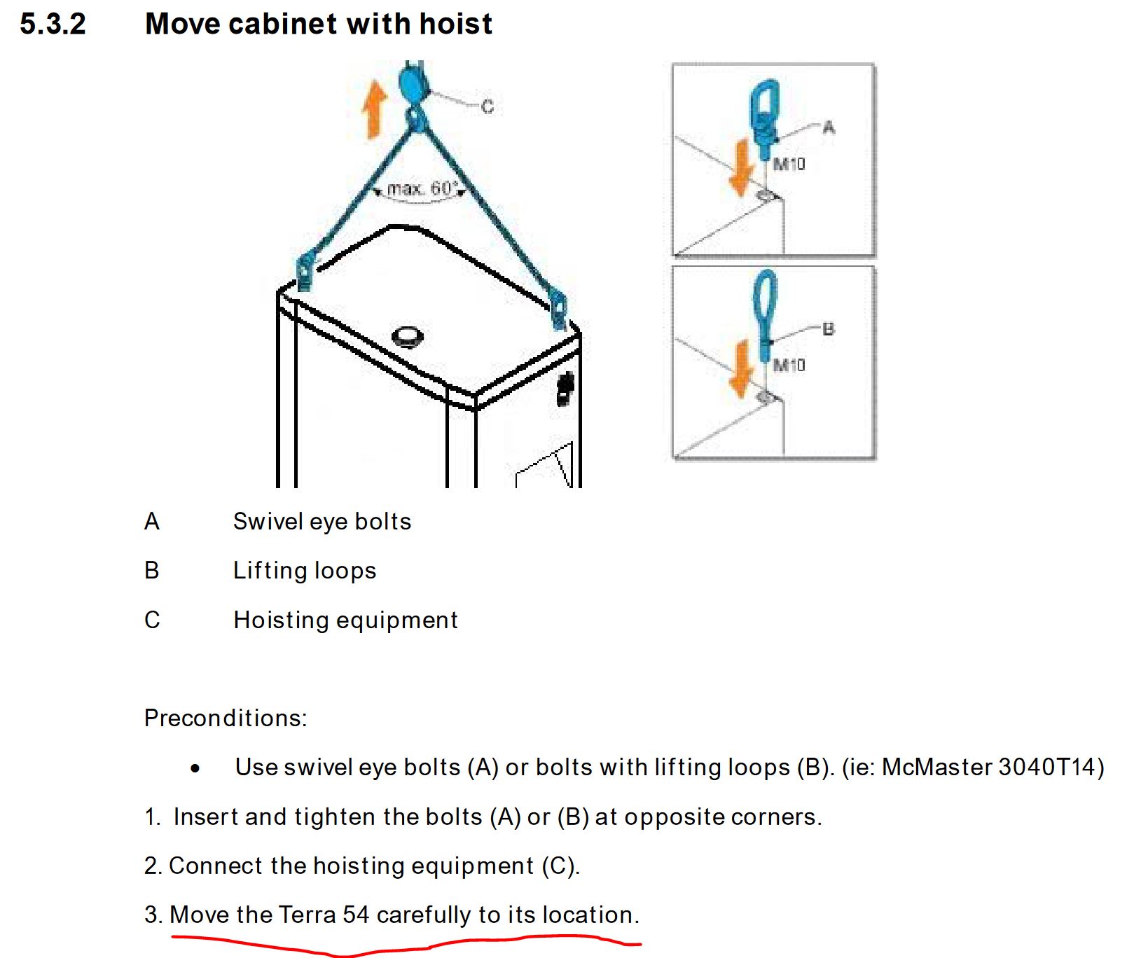
Ok lets lift up this monstrosity using the prescribed method show in the user manual for the 54' model. We're in luck and this does actually use M10 lifting eyes. There's four M10 threaded holes on the top of the unit. With some help from Ciaran, the chain host got the top of travel and to get the unit fully vertical it took a bit of a push and pull to get it on its 'feet'. To keep it from toppling over I'm going to leave it lashed up to the ceiling hoist. I grabbed some of these super excellent locking wheel ratchet things [link]. To make this monolith mobile the plot is to make a simple weldment cart, keeping in mind preventing this from tipping over is a priority, so not adding unnecessary height is a plus. Ideally, with a smaller lifting strap, i have enough space to lift this up and onto a quickly welded together rolling cart. 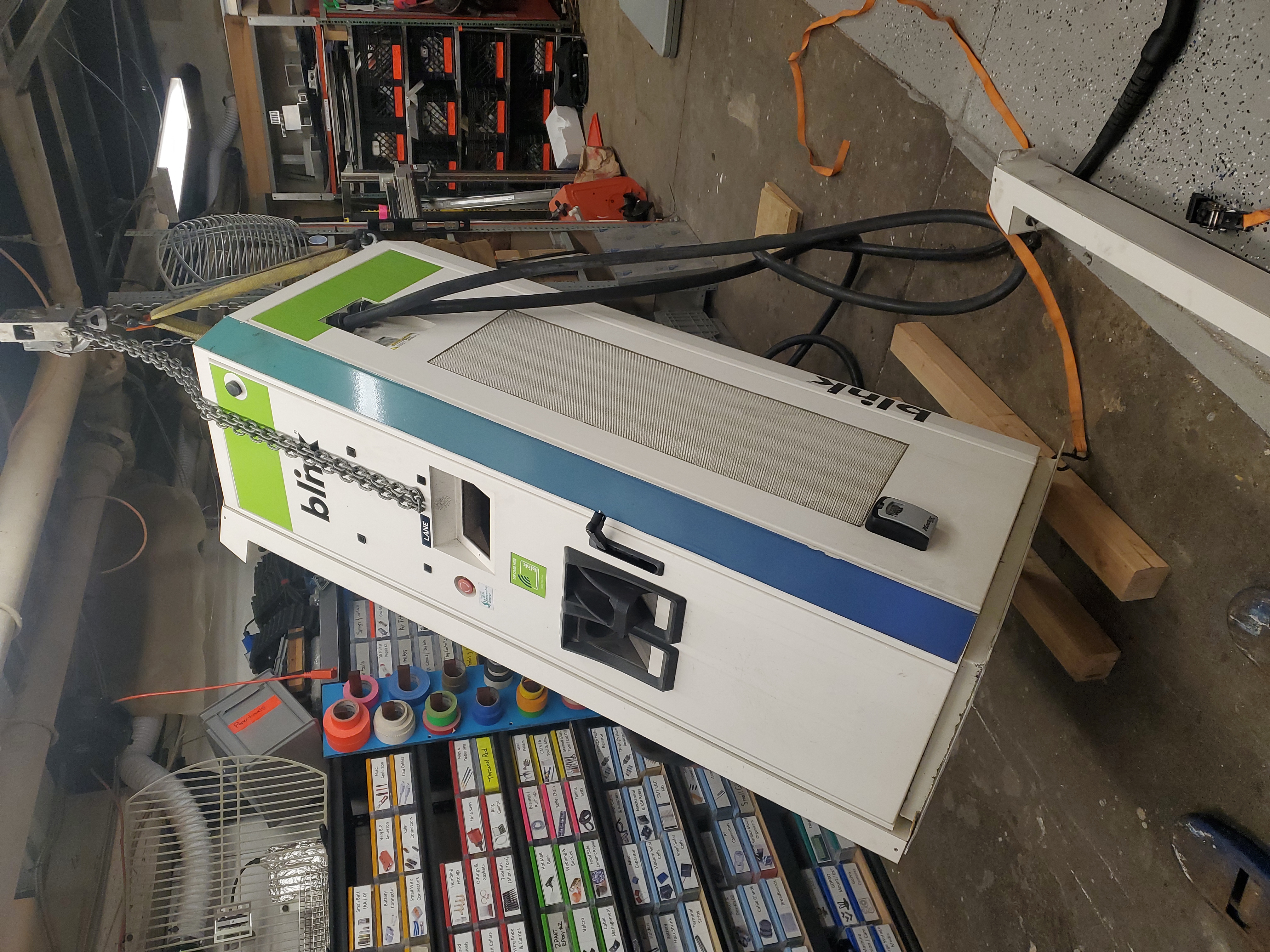
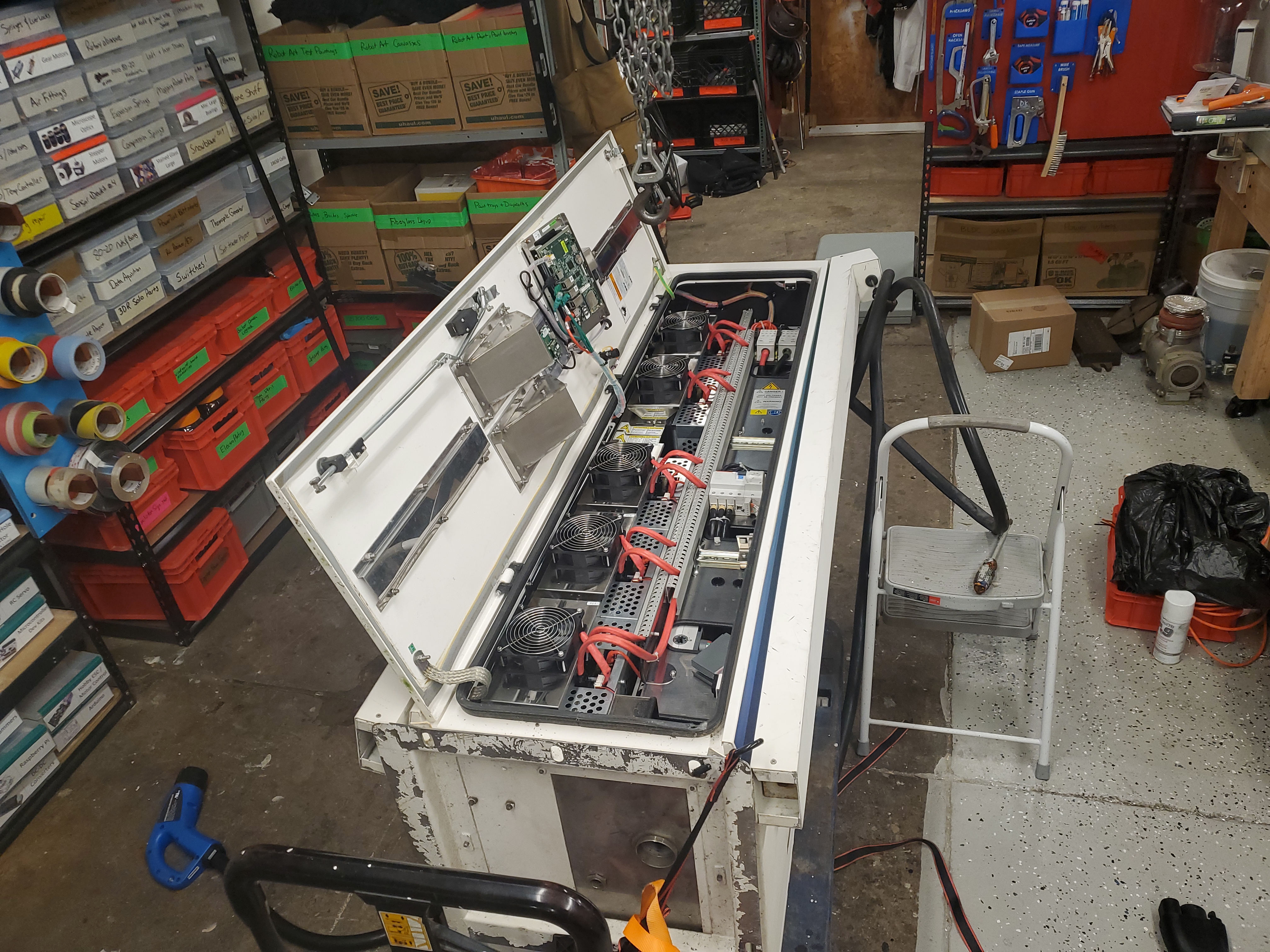
With the charger standing upright for the first time since it was loaded on the pickup I started by working open the side panel doors. The right side door contains all of the electrical interfacing, including the CCS / CHADEMO outputs, but also has all of the interface to the inverter modules. The left side door is nearly completely empty, as it appears to only be for access 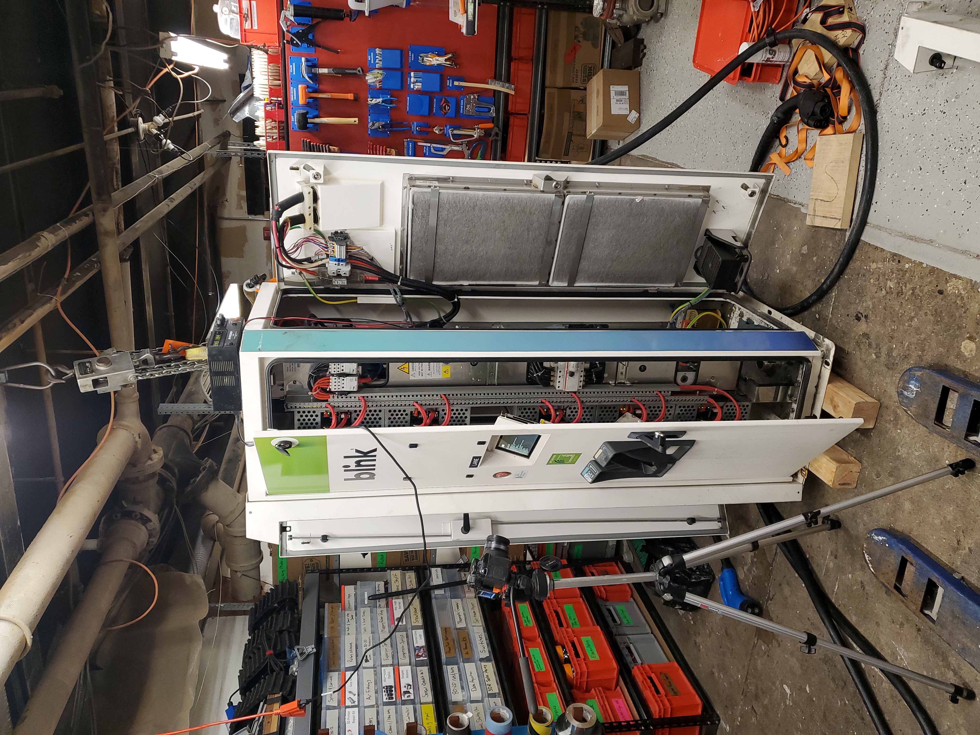
After supplying external 24V for logic power, here's the hardware booting up. Note parts of the wake up sequence is sped up due to it taking forever to get to the point of displaying the main overlay status. Note that i could have probably used the large DIN rail supply in the unit and fed 110v into its input, but that would not give any immediate indication of current draw, which is useful for diagnostics. Upon application of 24V, the unit began booting and also spooling up / testing some of the cooling fans. Current peaked at around 5.5A, which is fortunate as that supply peaks at 6.6A. 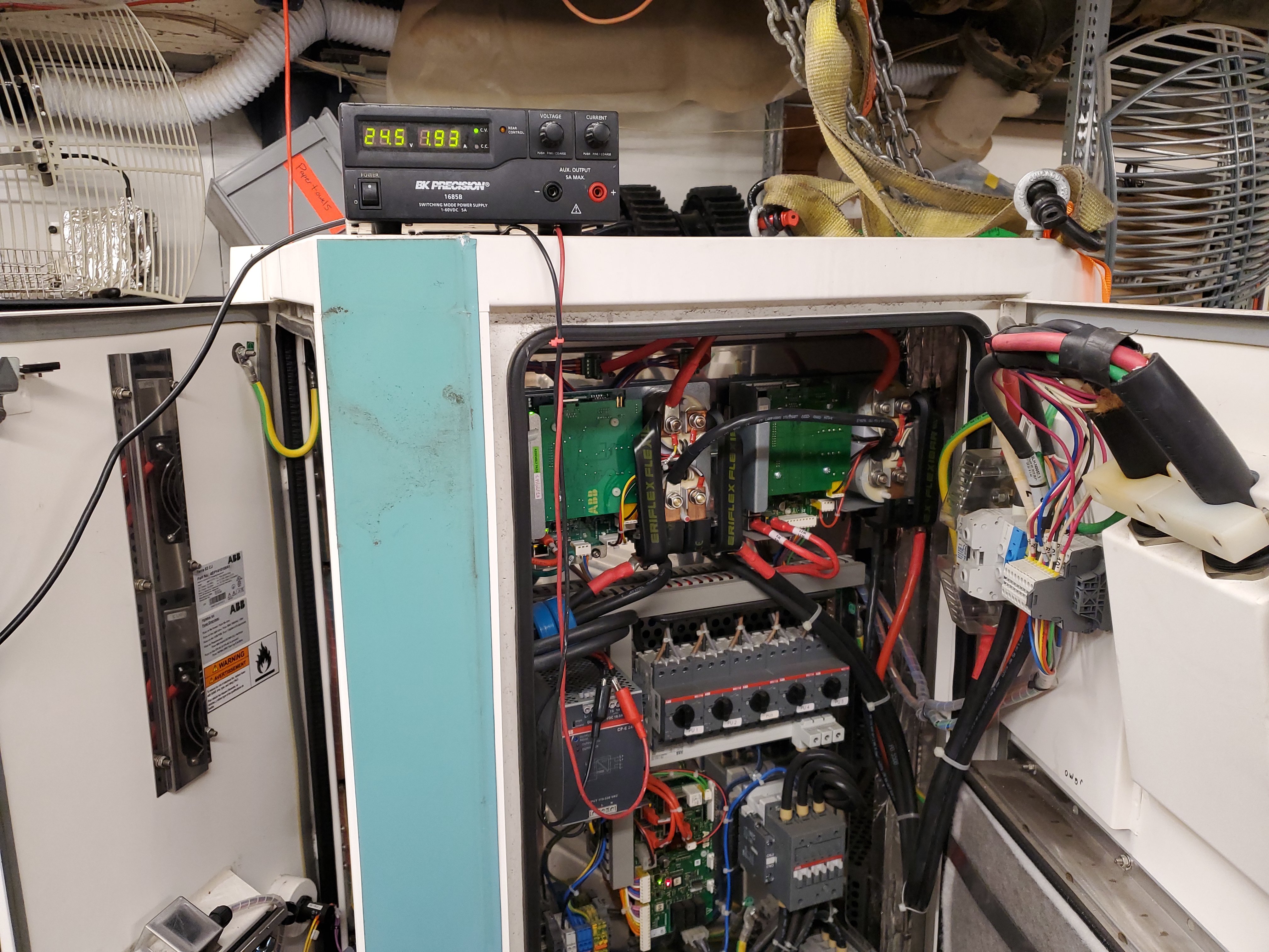
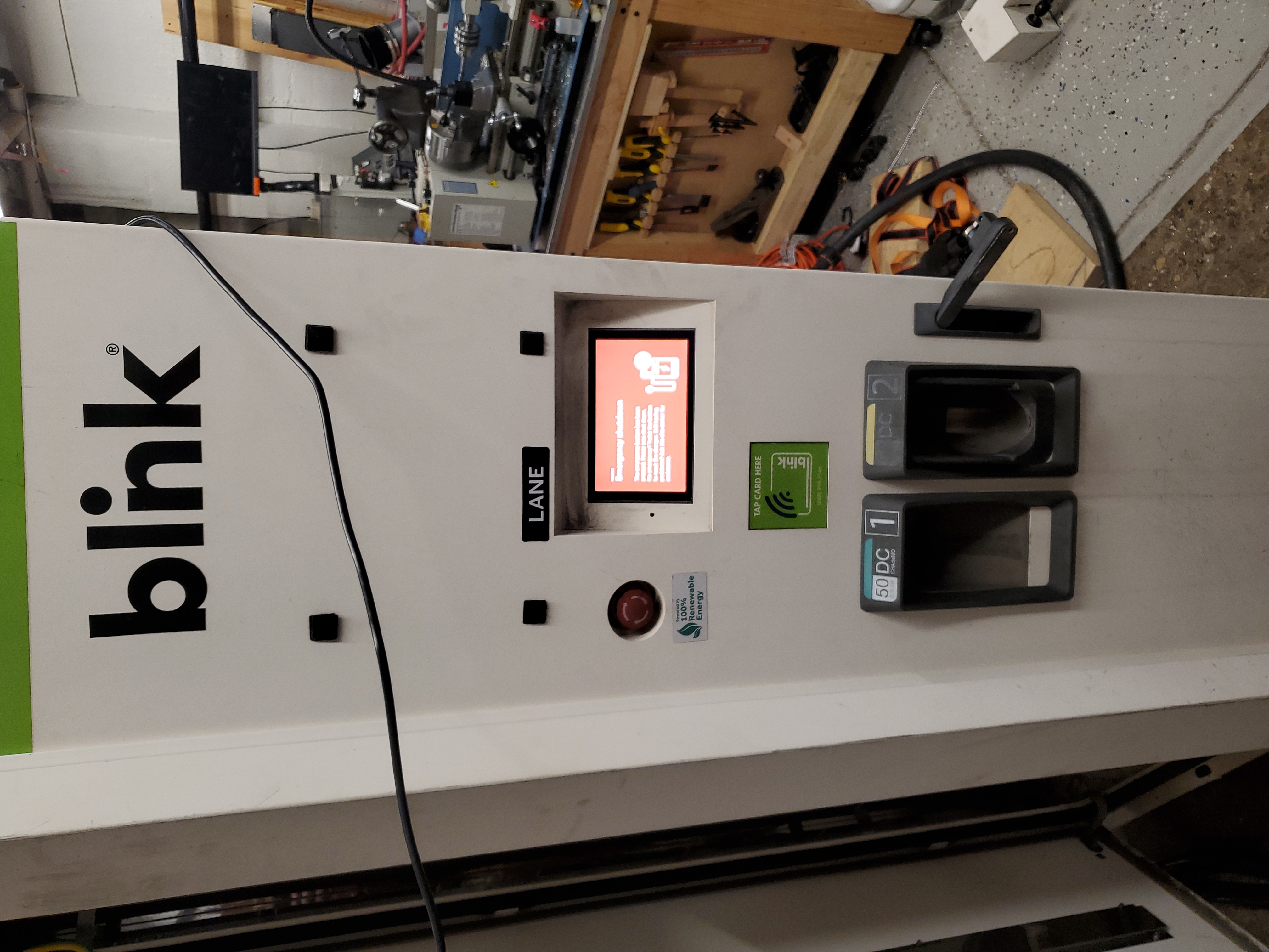
Without further to-do, here is the boot sequence of the unit, with the large power supplies offline and just the 24V bus powered up. First boot without the 480 inverter powerAfter the first bootup via just powering up the 24v logic rail, you end up with a charger out of order indication. The 'EN' button / touch interface doesnt seem to respond, and the question mark also seems to not actually do anything. 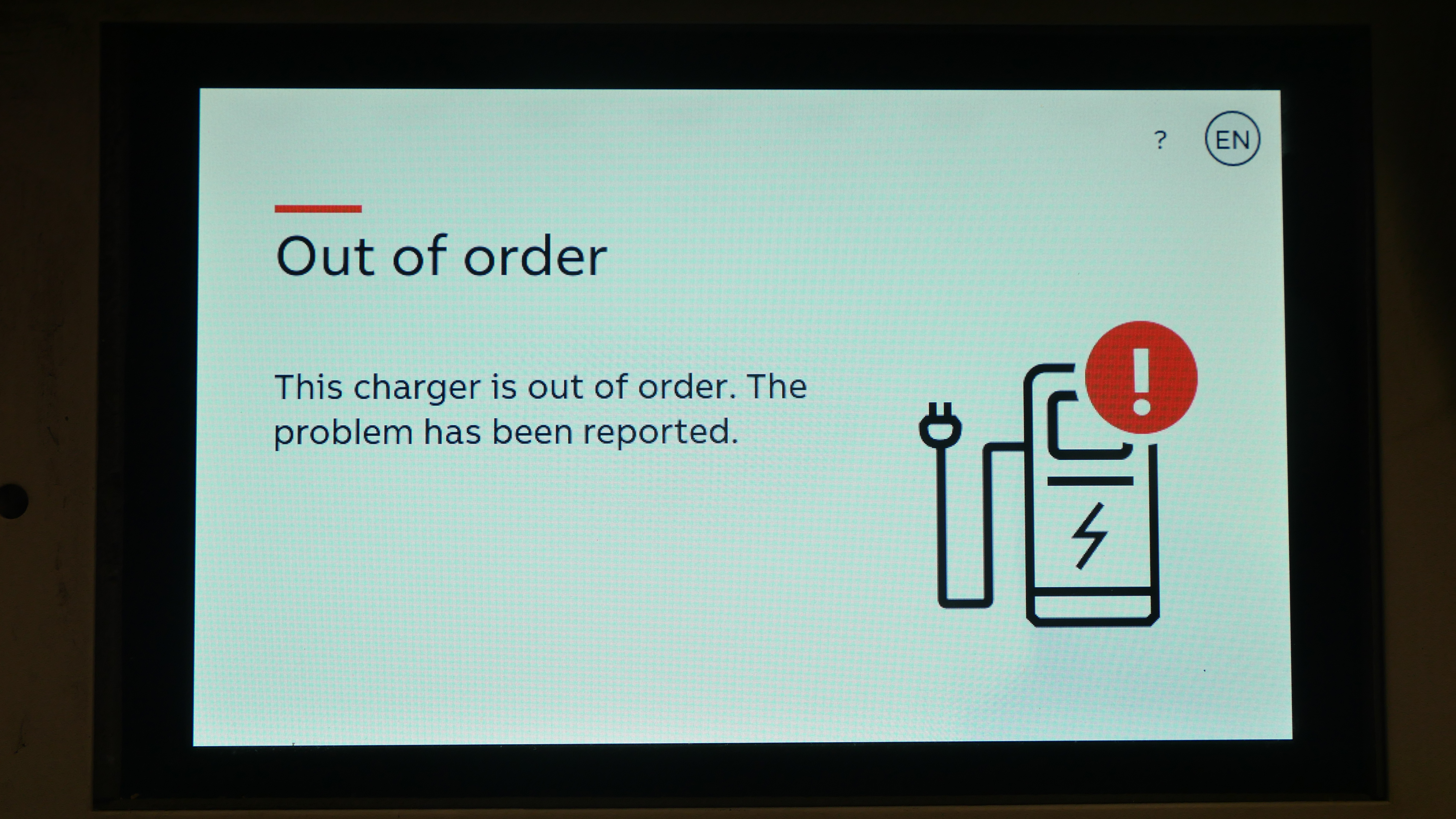
Does E-Stop still workWith the unit booted up, I hit the front panel e-stop. It did 'just work' which is nice, after re-setting the e-stop it returned to its previous screen. 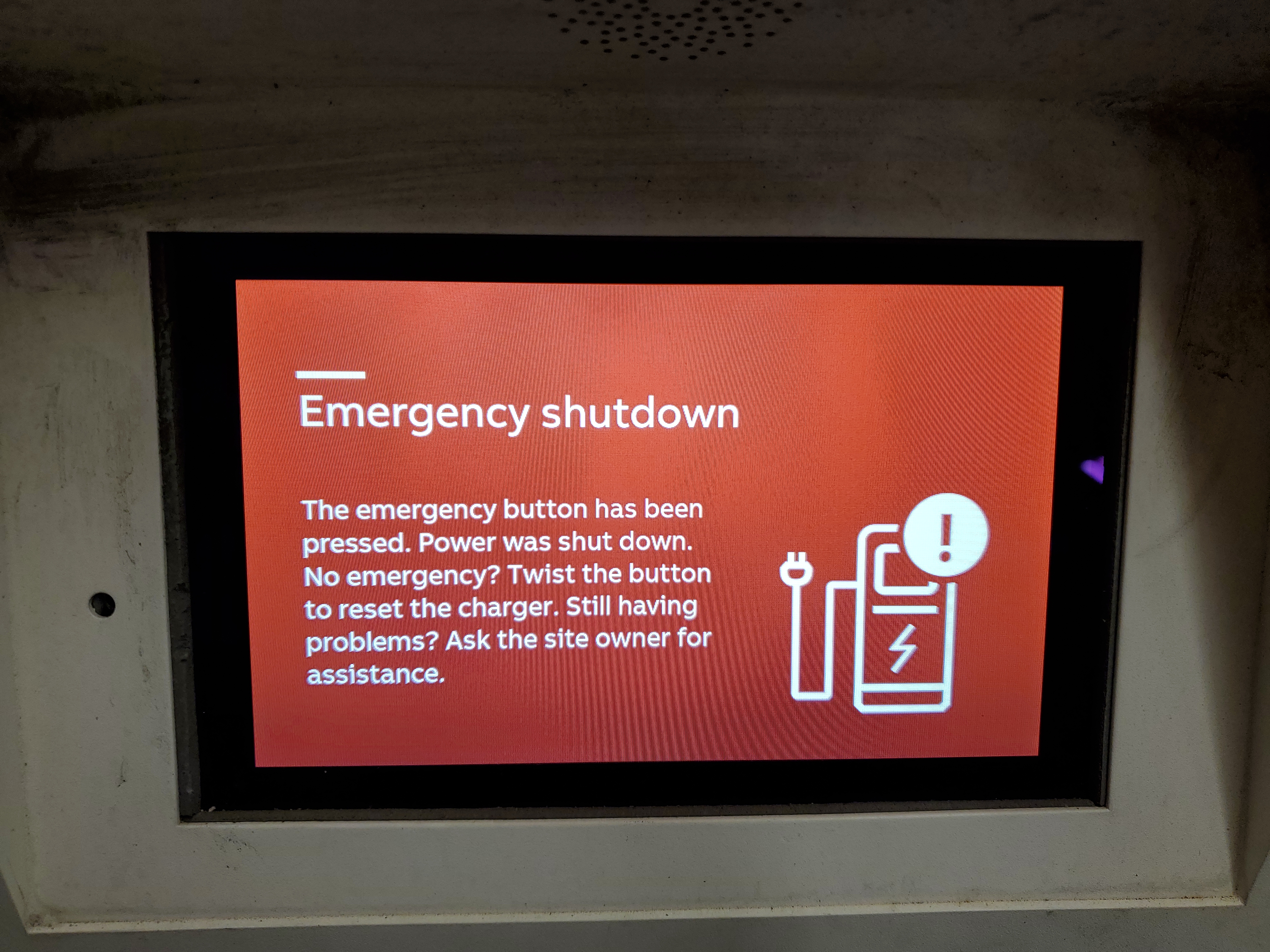
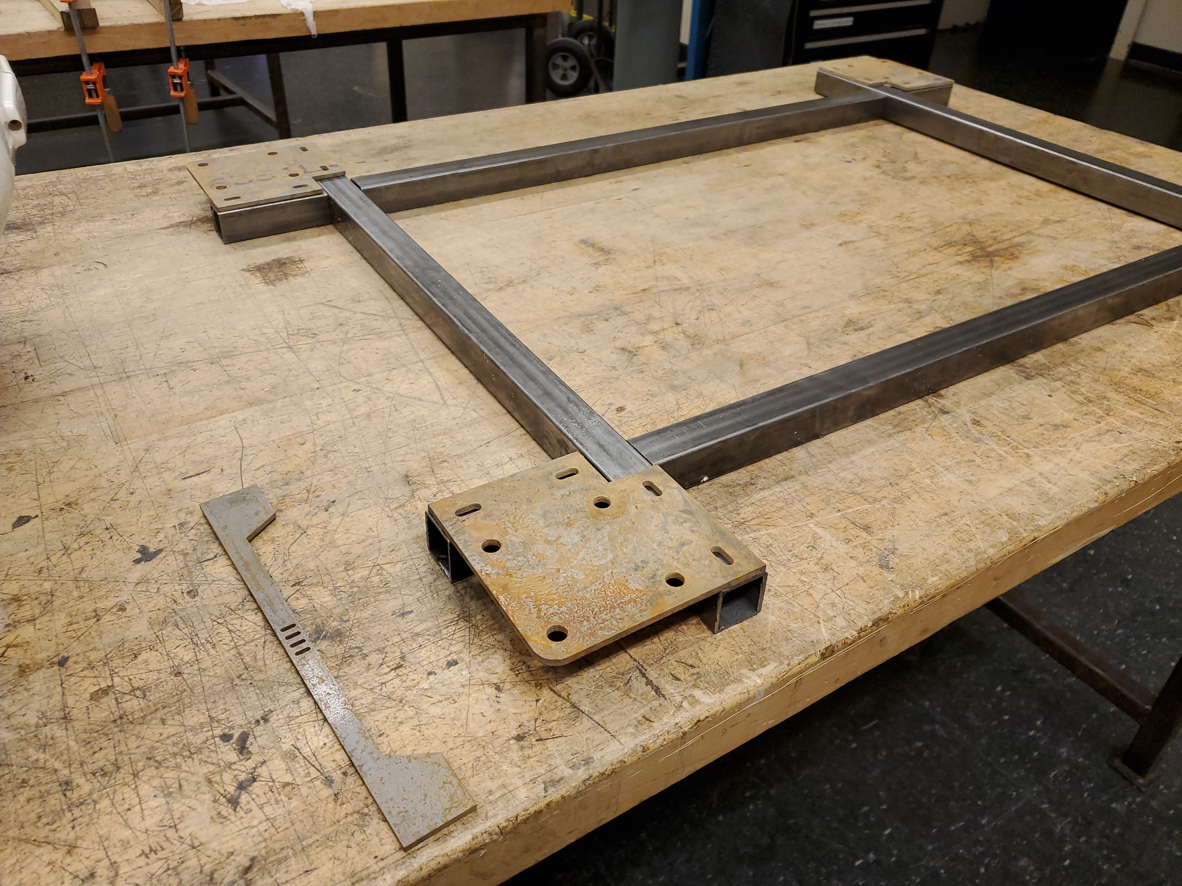
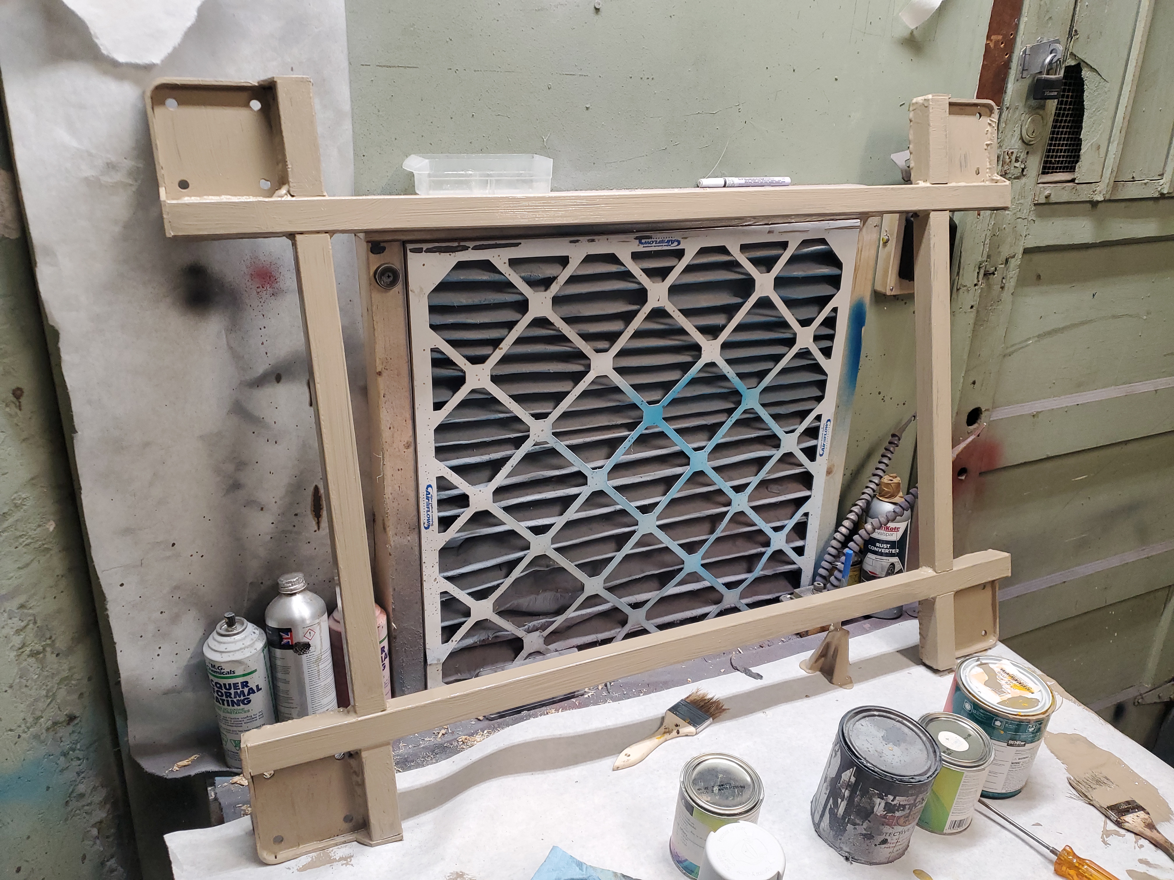
The charger needs wheels: Time to make a cartGiven the form-factor of the charger, its somewhat awkward to just add wheels. This is intended to sit on a concrete pad, so none of the base-plate has sufficient mounting for just adding casters. Tall casters at the corners would also make this extra-tippy, and given how heavy it is that's not something I was excited about. So we want casters that can become solid leveling feet, and we want them further out from the base footprint to limit the lever arm / reduce the tendency to tip over. Some rough cad and quick cuttingWith some coarse measurements of the base, we can sort out materials and order them in to get this done on a weekend. For materials I opted for mild steel square tubing and "mild" steel plate stock. Nominally the ratio of plate thickness to tube thickness should be somewhat close to 1:1, partially for weld adhesion and partially for structure. If you picture hyper thin walled tubing connected to 1/2" thick plate you end up with the thin tubing approaching melt temperature significantly faster than its higher thermal mass counterpart. Ideally they approach melting temperature at the same time and bond. In this case the tube was 0.083" wall and the plate was 0.160". You're about to scream "hey Dane that's like 2:1 thickness ratio", and you're right, however if you look at where the structural weldments mate, you notice that the edges of the tubing mate to the plate, and the edge of square tubing has access to much more thermal mass than a flat stock sheet, and you can get away with dissimilar thicknesses easier. I also did not want to spend too much and, if possible fit everything into two 6' pieces of square stock tubing. List of hardware for the cart:
Waterjet, oh garnet cladded mistress of the shop, make me some parts.This design uses 2D waterjet cutouts per caster, one to act as the weldment that holds the caster and a second to add a structural brace around the perimeter to prevent sagging. Connecting 2D parts together really makes prototyping and assembly quicker as there are many more options for 2D Parts than large time consuming CNC assemblies. Technically the top part could be bolted to the square-tube frame and the wrap around part tapped with 4-40 screws if welding was unavailable. If I were to go that route, alignment cutouts would have been a better option. In this case I was excited for an excuse to MIG again, as it had been a while. Overall the jetting for all four caster brackets and four support wrap around brackets took around 35 minutes, which is fairly speedy all things considered. I did goof up on one of the caster brackets but it was serviceable and easily fixed by filling in spots with weldment. 
The slot cutouts in the plate allow for more welding area, attaching the steel tube to the plate at the top. I somewhat forgot to fully over-fill these with weld, so when I was doing surface clean out they did look a little pitted but alas this is a cart not a cosmetic structure. While i waterjet these locally, this also could have been laser cut at places like sendcutsend or jetted at bigbluesaw. 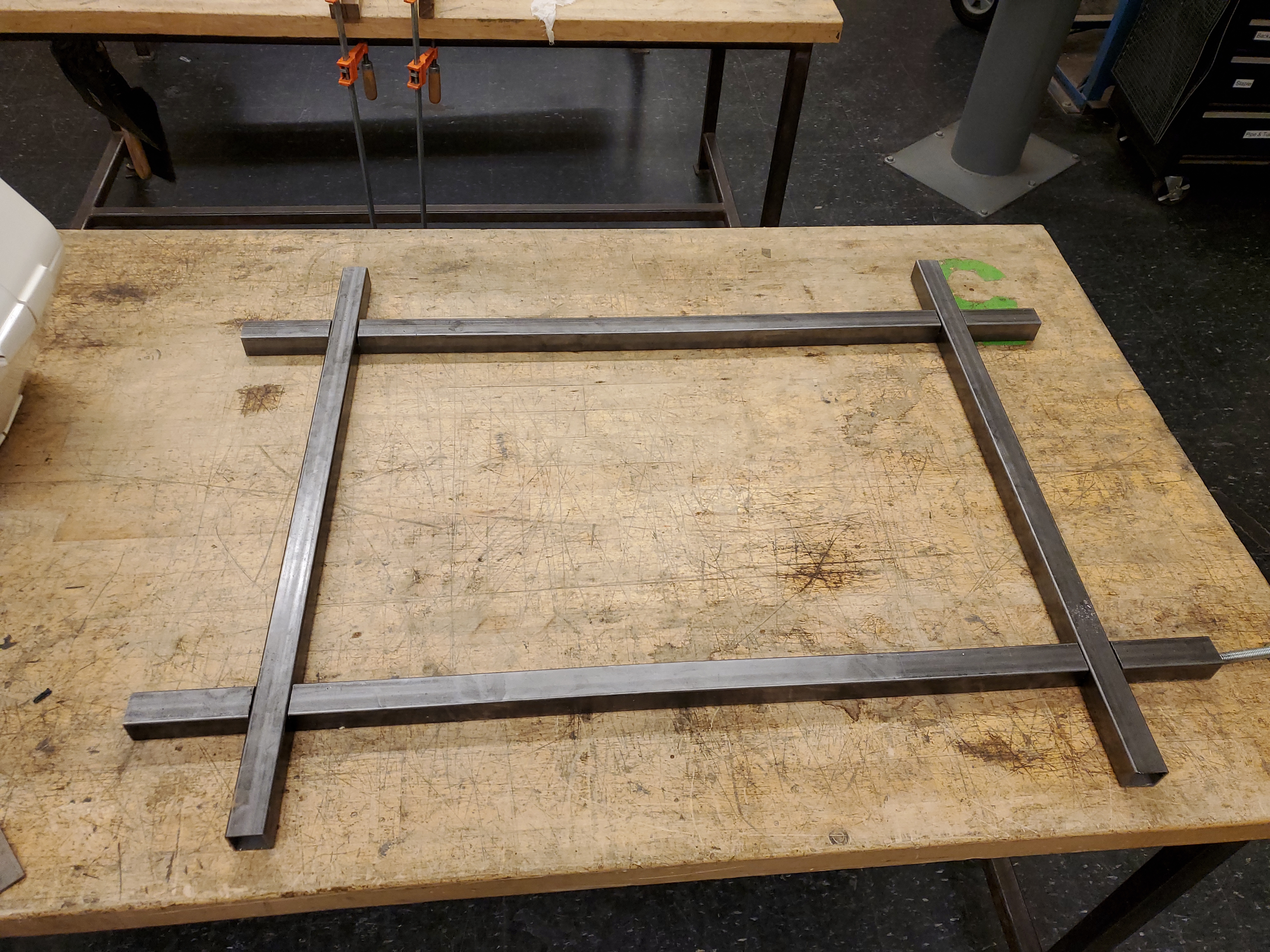
In some Friday-afternoon haste, I used a Bridgeport manual mill to notch slots in the tubing and neglected to take any photos of the process. The tubes were cut to length and then I just hastily milled halfway through, leaving adequate spacing in case alignment wasn't quite right. The beauty of mig-welding is how forgiving it is. With the plate holding the caster mocked up everything looked right. Next up is some surface prep and welding. This photo was taken less than 3 hours after waterjetting and somehow the surfaces of the 4130 plate had already flash rusted. 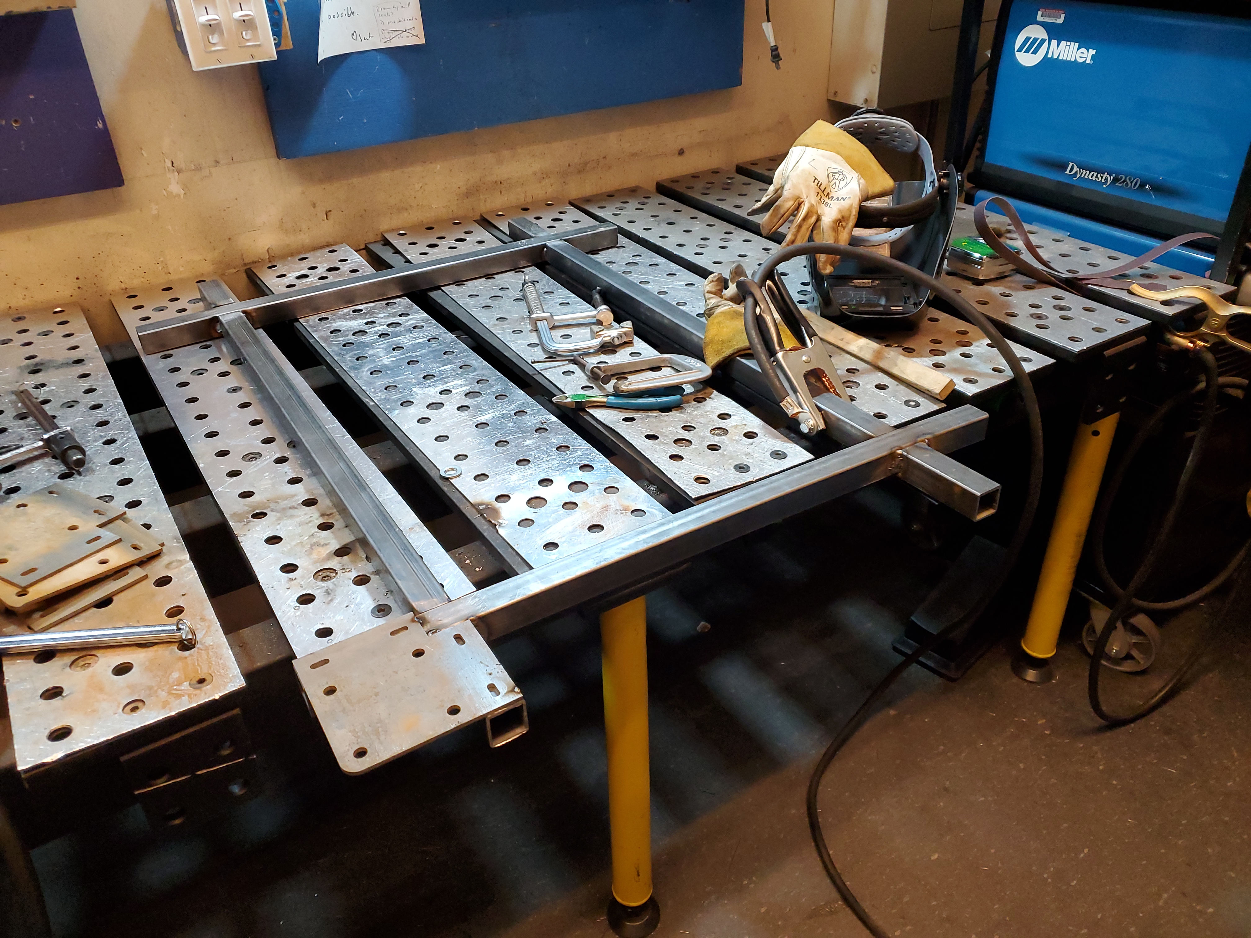
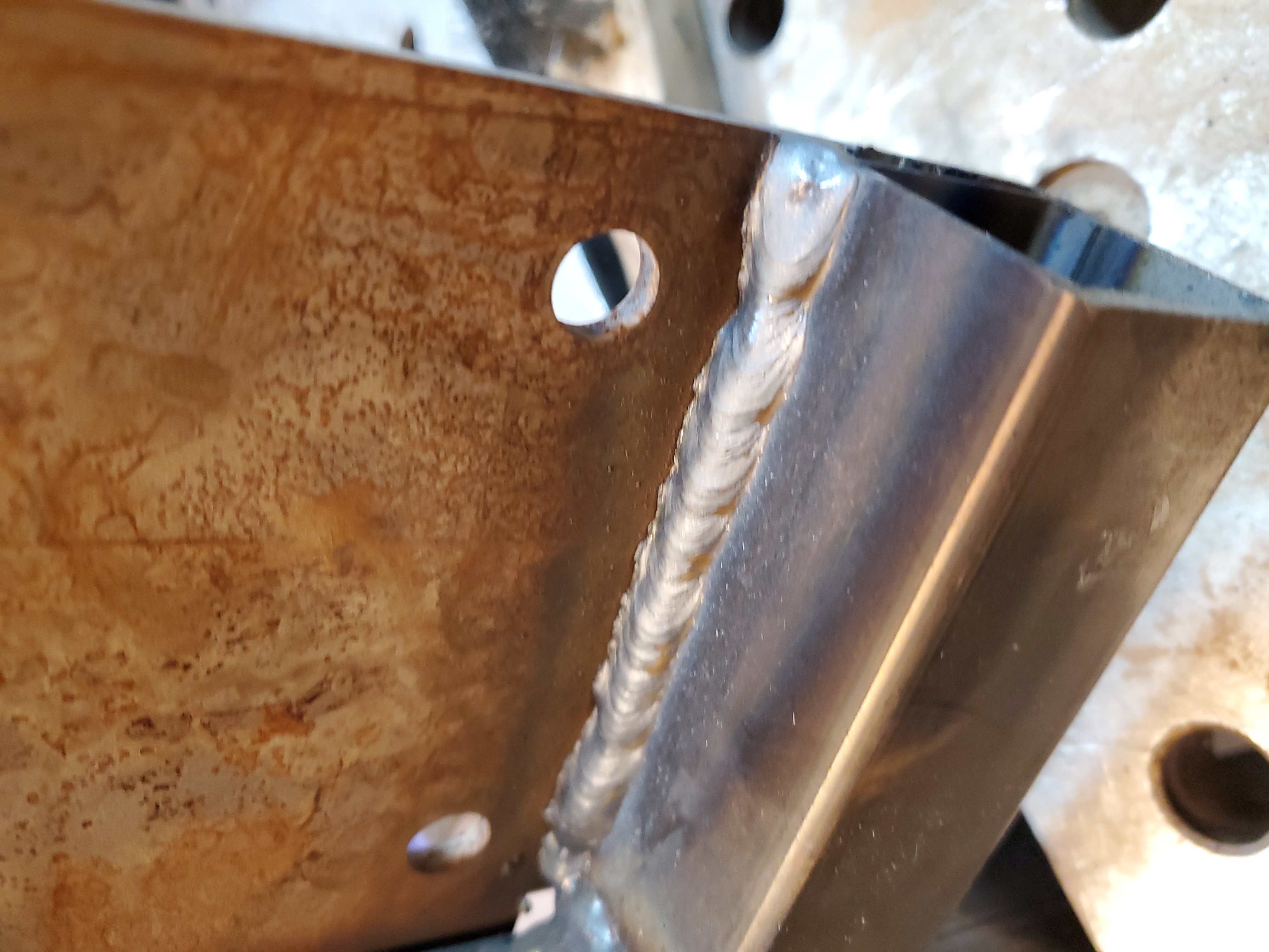
I will remark again as to how excellent the D-LAB welding setup is, and how fantastic of a job Jack Whipple does maintaining that space. These first tack and line welds were done with a millermattic 355 MIG, and it is a monster. I did finally have a chance to use something I made mid-pandemic but never got a chance to test out, an auto welding filter for a DSLR. This project is documented here [link], and is nominally just a simple adapter to fit a welding visor insert in front of a Panasonic M4/3 lens. I really like how it came out, its a simple print and in theory should just do the thing. It turns out it's really awkward to properly video MIG welding. You do not want the camera in the blast radius of the MIG, once you start welding your visor goes dark and you can't see the camera screen, the green hue of the lens protection makes it hard to focus and well, its hard to get the exposure right. I think the 15$ welding visor inserts are great but somewhat limited for video recording. I think TIG welding may be a lot easier to film given that you can get the camera closer to the arc and there's less weld splatter. For a first pass the auto darkening weld cover proof of concept was actually pretty good, but it looks like since 2020 there's better options out there in terms of visibility and image clarity. I splurged and grabbed an ArcOne T240-10 Tradesman to try a modern new option and will report back next time I'm welding. I did want to try and weld up a bike this winter so clearly I need this pricey gadget to document the process. Ok but what does the welding look like in weld-o-vision?I only did some basic image cleanup to try and dampen the bright spot, the footage is pretty good, but very monochromatic, which I guess is exactly what is intended with the more budget friendly welding insert. This is the inner weld underneath the cart where the caster plate mates to the tubing. Ok we're getting somewhat off-topic here, lets get back to the cart. Here's everything welded up. Its not perfectly flat to the wooden tabletop but as the Mason decrees, "three points define a plane" and honestly I did not expect it to sit perfectly flat, given the amount of weight pressing down on the casters, its likely that it will elastically conform to the concrete floor it will ride on. 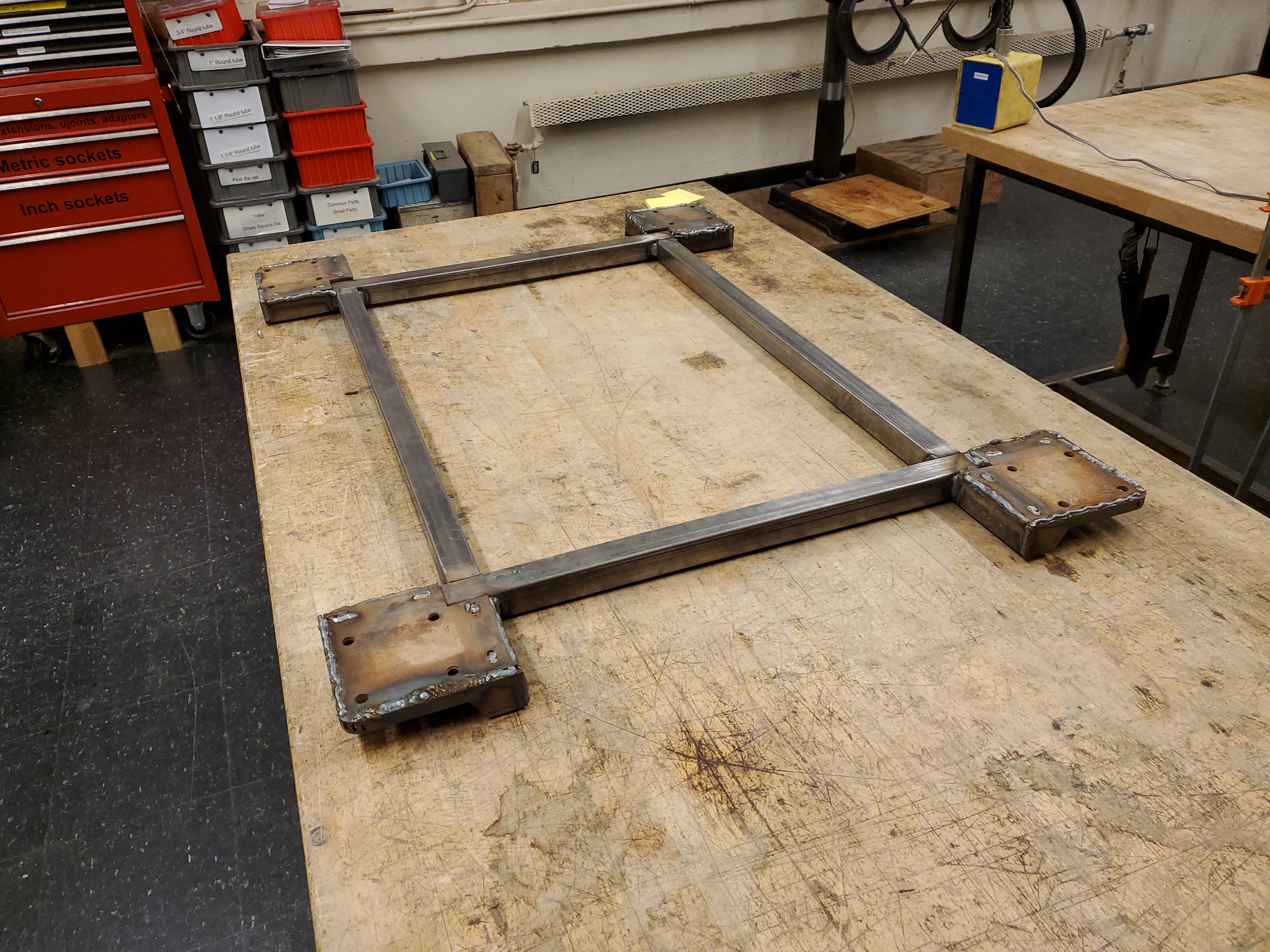
Do Not use mystery paintI cleaned up the surfaces with sandpaper and then IPA with a rag to get all the surface contaminant free. To 'avoid a trip to the store' I used some mystery canned paint to coat the cart, in the hope that it would dry in time to attach it to the charger in the evening. At homedepot there's a cart of mystery paints for like 75 cents and sometimes its great. As it turns out the mystery canned paint was likely latex wall paint, approximately the worst choice to bond to non-primed steel. 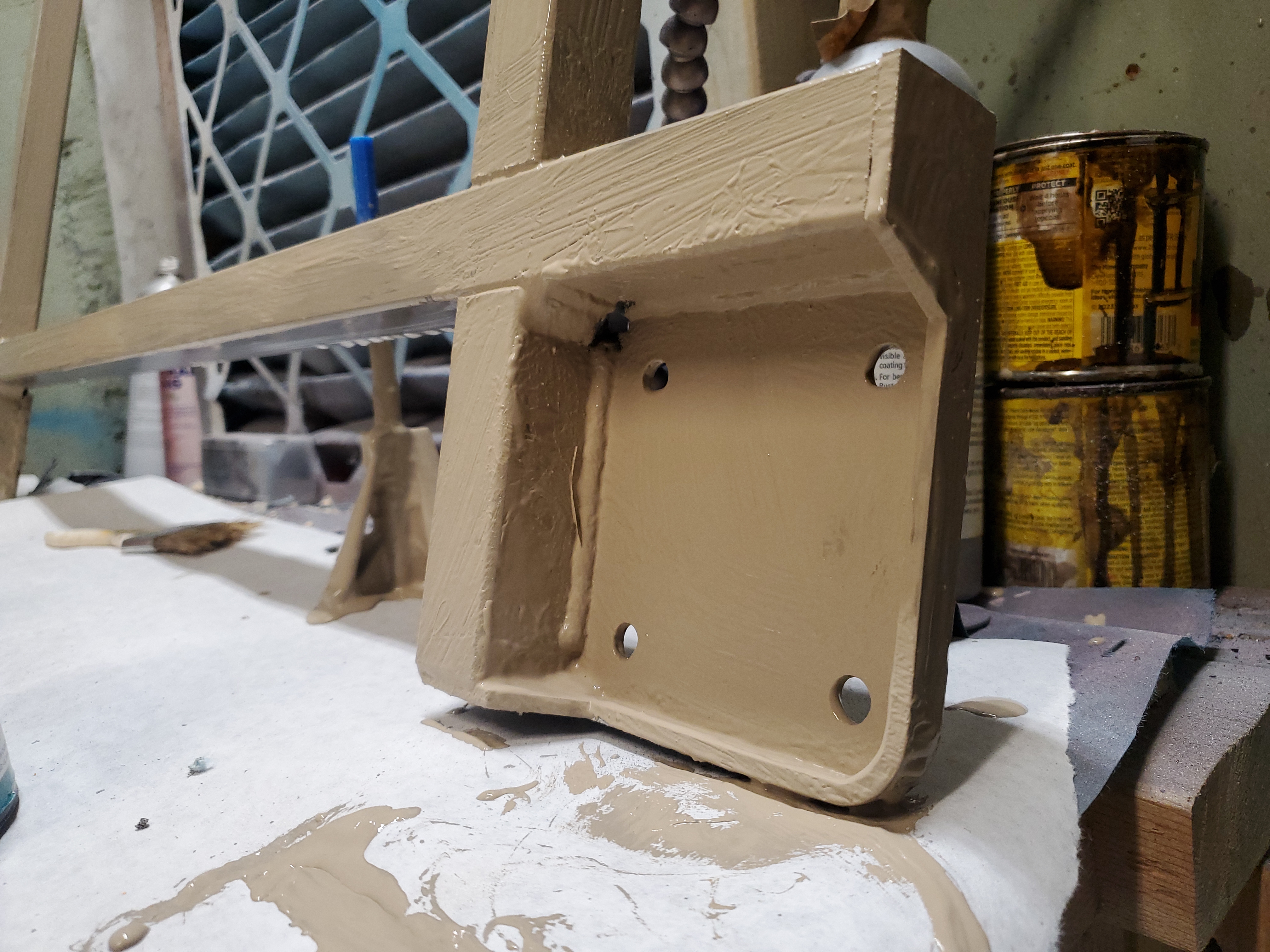
At first it looked OK, not the biggest fan of brown but it's a cart. After a few hours i went to move it and the paint mostly slid off. I imagine there's a colloquial saying about how saving time generally makes things take longer, but here we are. I spent the next 45 minutes stripping off the brown latex paint, and subsequently priming and spray painting the surface black. I'm not the biggest fan of spray paint but it does setup a lot quicker than brush paint.After a few hours it was time to mate the cart to the heavy charger. 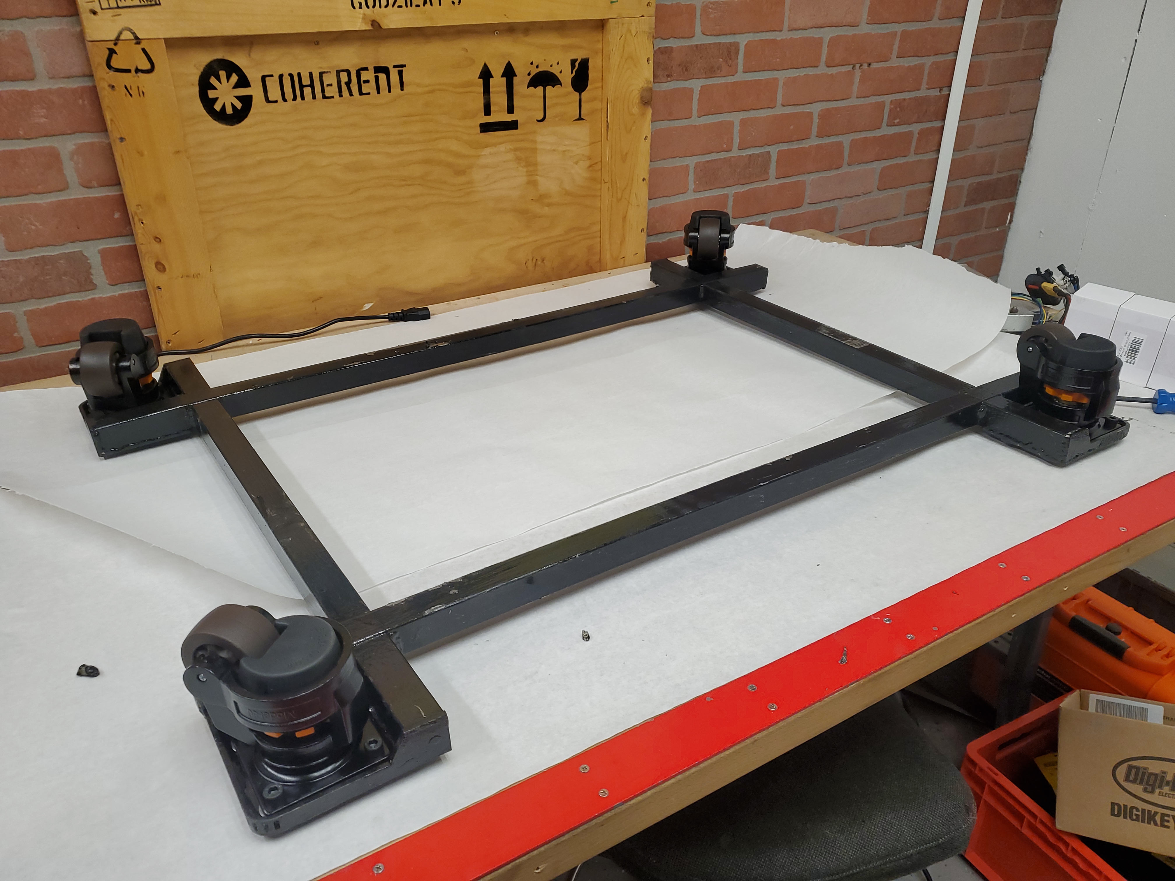
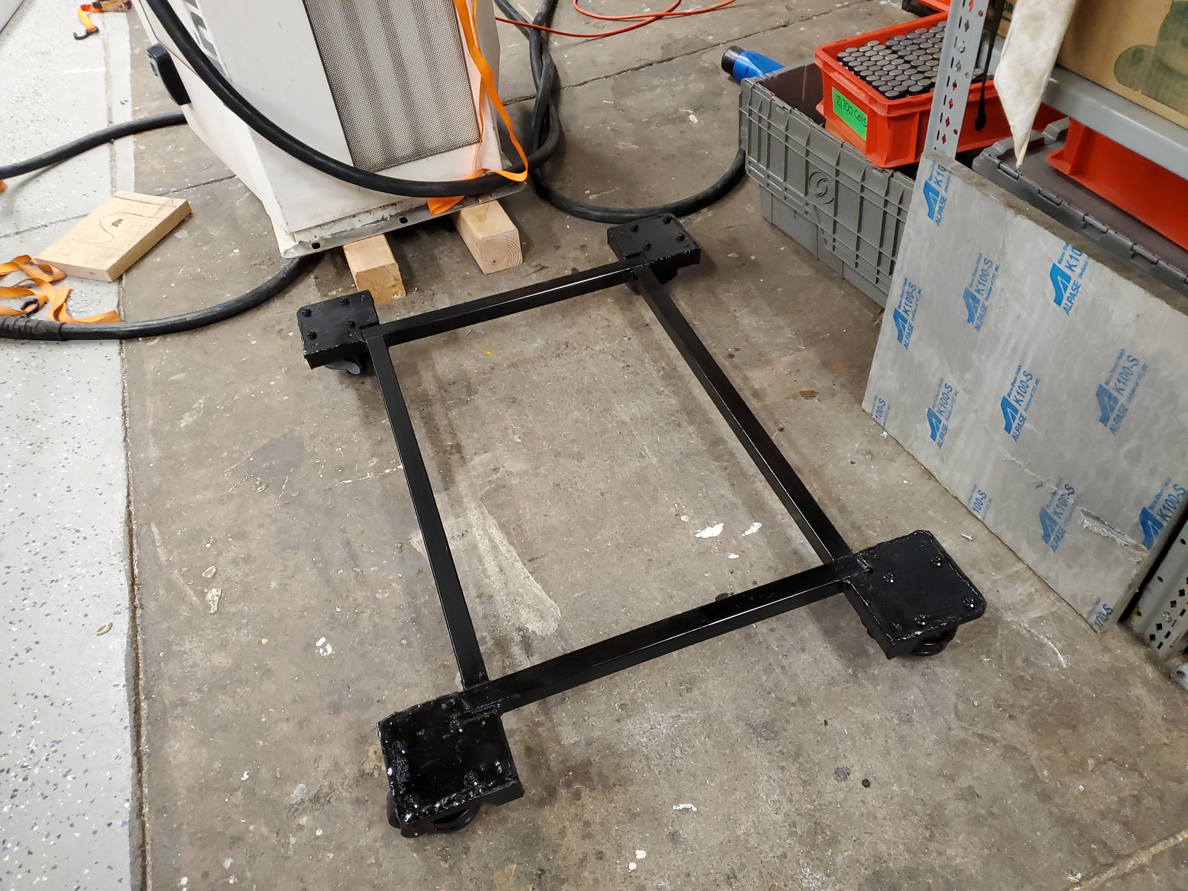
The cart lives along the perimeter tubing, which also have the bolt pattern to mate to the existing mounting points. The casters function as leveling feet so wherever this ends up it sits on the feet and hopefully stays supported. The cutouts in the initial plate are actually for the spot that the charger base plate rests on. Using a short strap and a hoist, I lifted up the charger, again with the help of Ciaran, and slid the cart underneath. Happily it fit perfectly. I debated pre-driling to match with the charger's bolt pattern but opted to do that after it was mounted. 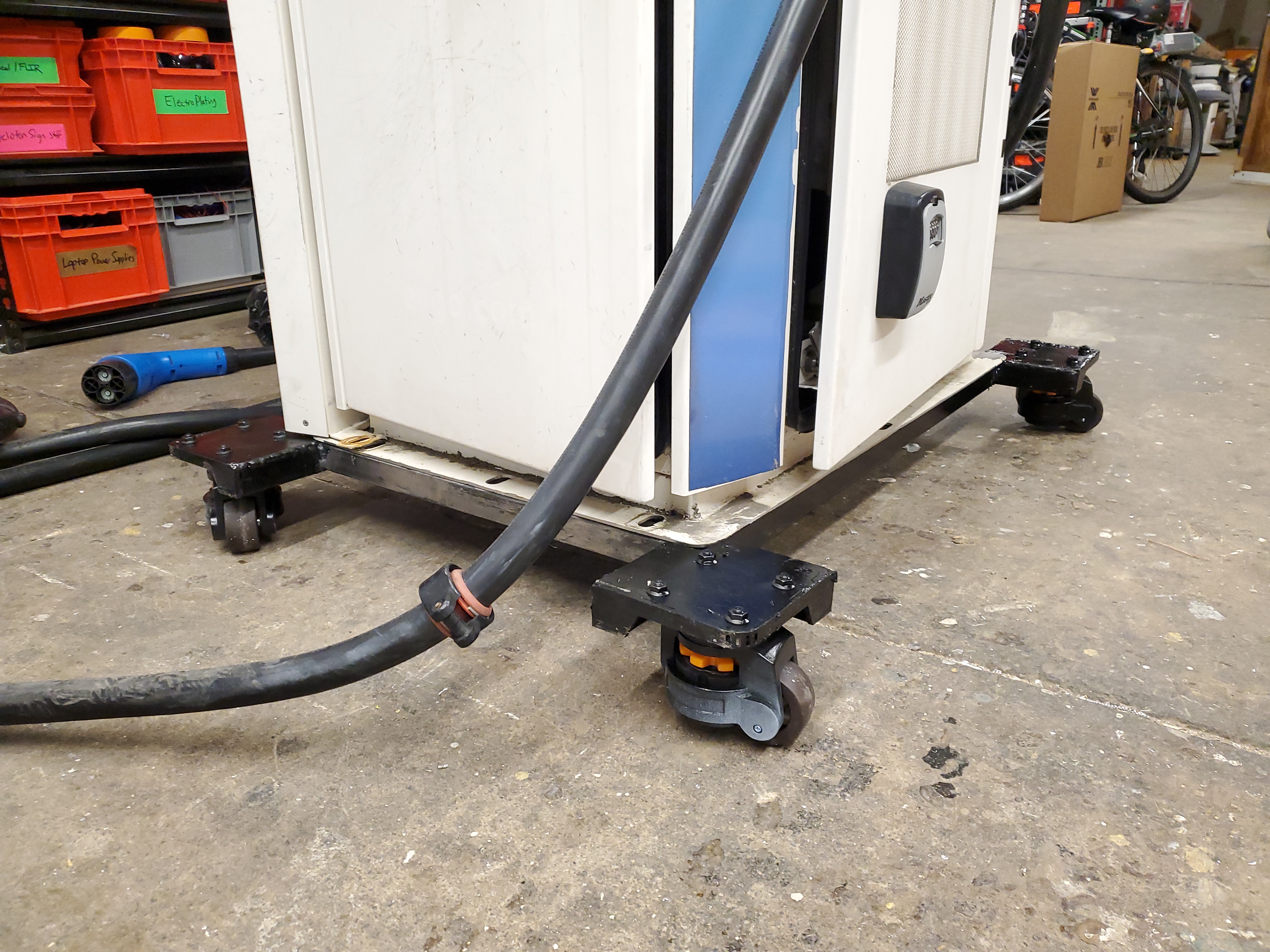
The caster-cart came out great, I was able to wheel the big charger around to its new location without much effort and then spent a bit with the leveling feet to have this sit in place. At this point, I stared at this "blink" monster and it hit me, it needs googly eyes. I grabbed two large googly eyes and then made little 3D printed magnet mounts so that these are removable if need be. Maybe I should have gone with green, but blue filament was in stock. 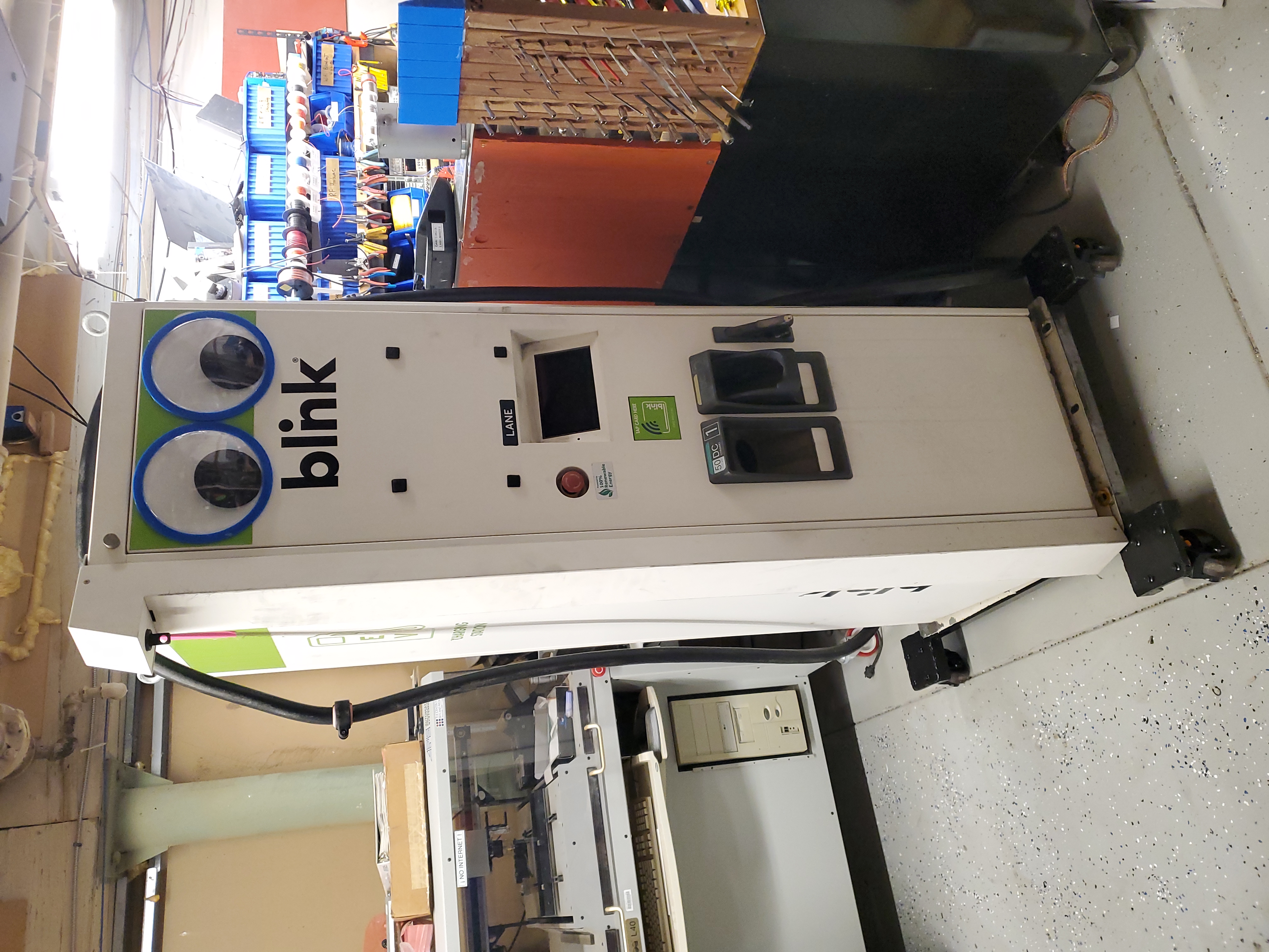
Talking to the charger: How does it appear over a non-internet connected network?With the SIM card removed, the charger itself is isolated and cant call home to brick itself or whatever the ABB home gateway does. Given that this charger can also use a conventional CAT-5 network connection, lets connect it to an AP that can serve up DHCP but is not connected to the greater internet. Using this isolated network and a laptop connected to that AP, we can start doing some interrogation. Is there some simple SSH login, or a configuration webpage? Time to find out. I grabbed a trusty old WRT-54G and set it up as a basic access point. This provided DNS for the charger, connected to Ethernet connection W20 on the single board computer. It turns out W20 is indeed Ethernet, not some magical ether-cat or can over cat-5 so that is at least some good news. On boot up, the charger found its DNS host (192.168.1.1) and got allocated (192.168.1.100). Exciting, maybe it has some webpage for configuring things. I gave zenmap (nmap wrapper) full beans and let it do an intense scan of all TCP ports 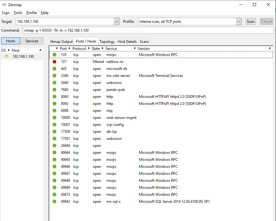
This is where things got odd, why does the control computer look like a windows machine, or at least zenmap really thinks (98% chance) this is a WIN-10 machine it's talking to. 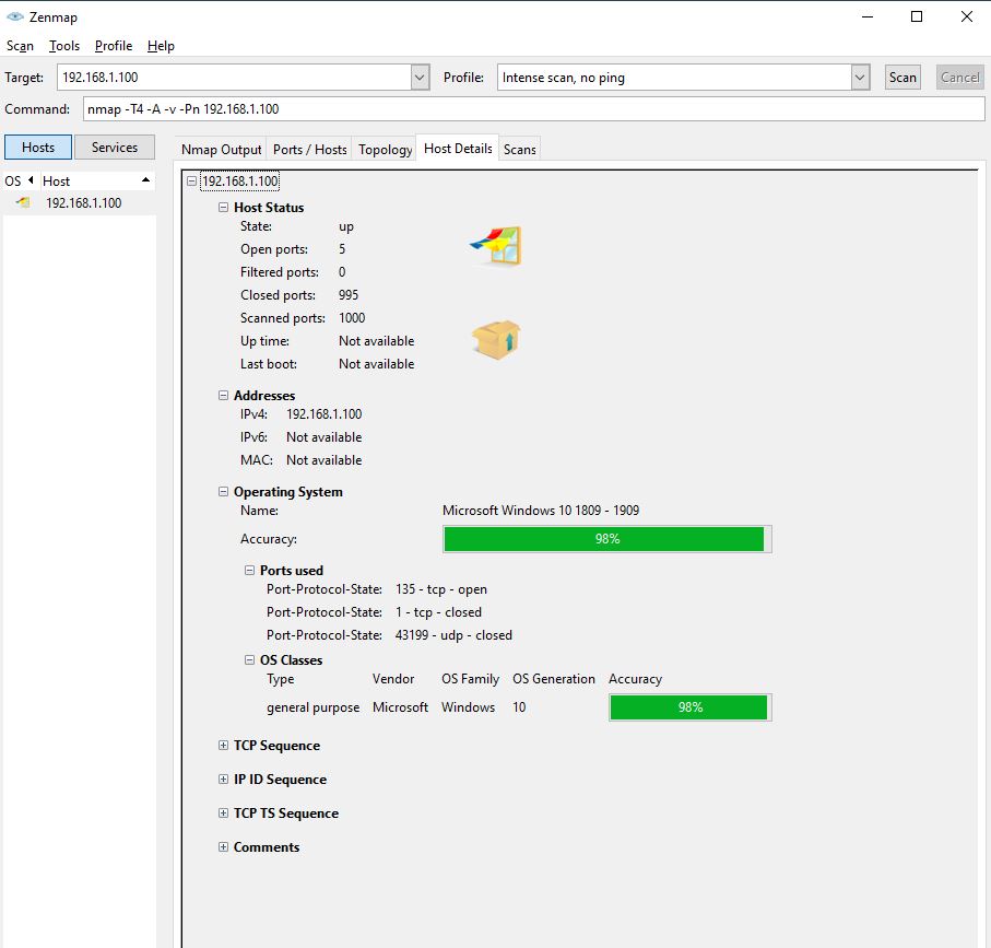
I highly doubt this as when the charger wakes up it calls out things like eth0, which is a hallmark of Debian / Linux land. None of these ports are hosting http webpages, but one of them does look really familiar port 3389 , thats windows Remote Desktop Protocol (RDP). What is going on here. For the sake of curiosity, lets see if a windows machine can start establishing an RDP session. 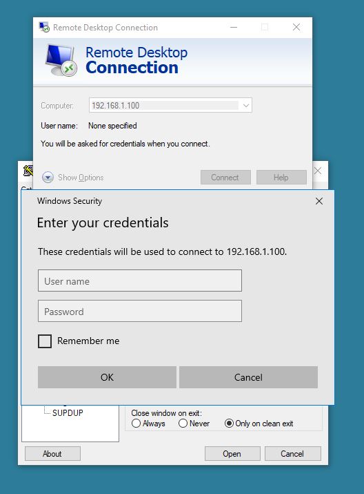
It is windows RDP! I have no idea what the username / password is but it is indeed windows RDP. My first guess is that this is what the ABB site folks log into to commission the thing? For a lot of these industrial gadgets, the PW is the mac address or serial number, or a portion of the serial number (last six digits), but I have no idea what the user is. We can dig down the brute force approach if need be but this might take a bit. What are the other ports:
TCP traffic / Remote Procedure Call Endmapping: This tells other machines what services the machine provides Windows SMB shares / file sharing. This can be Samba or CIFS. Wait is this thing hosting a file server? Its showing as 'microsoft-ds' in zenmap which is directory services, so it could be hosting a fileserver Windows Remote Desktop Protocol This port can be used by many things, but zenmap is showing "snet-sensor-mgmt", which may be webmin, a web-based sysadmin tool. This actually should show up in a browser if i go to 192.168.1.100:10000, assuming the old wrt-54g actually resolves ports greater than 255. Ok we have some new plans, figure out if there's a mountable SMB share hosted by the machine, see if the webadmin thing is running / visible, and worst case brute force the windows RDP login. Lets find out more about the single board computerI somewhat expected a PC/104 style board here, or with some wishful thinking maybe a compute module carrier board. This instead is unfortunately undocumented publicly. The image below is a screenshot from a video clip, but we find that this is powered by a TI AM3354 processor [link], but it also has a UART port This is exciting if that port is populated / just pipes out terminal outputs. 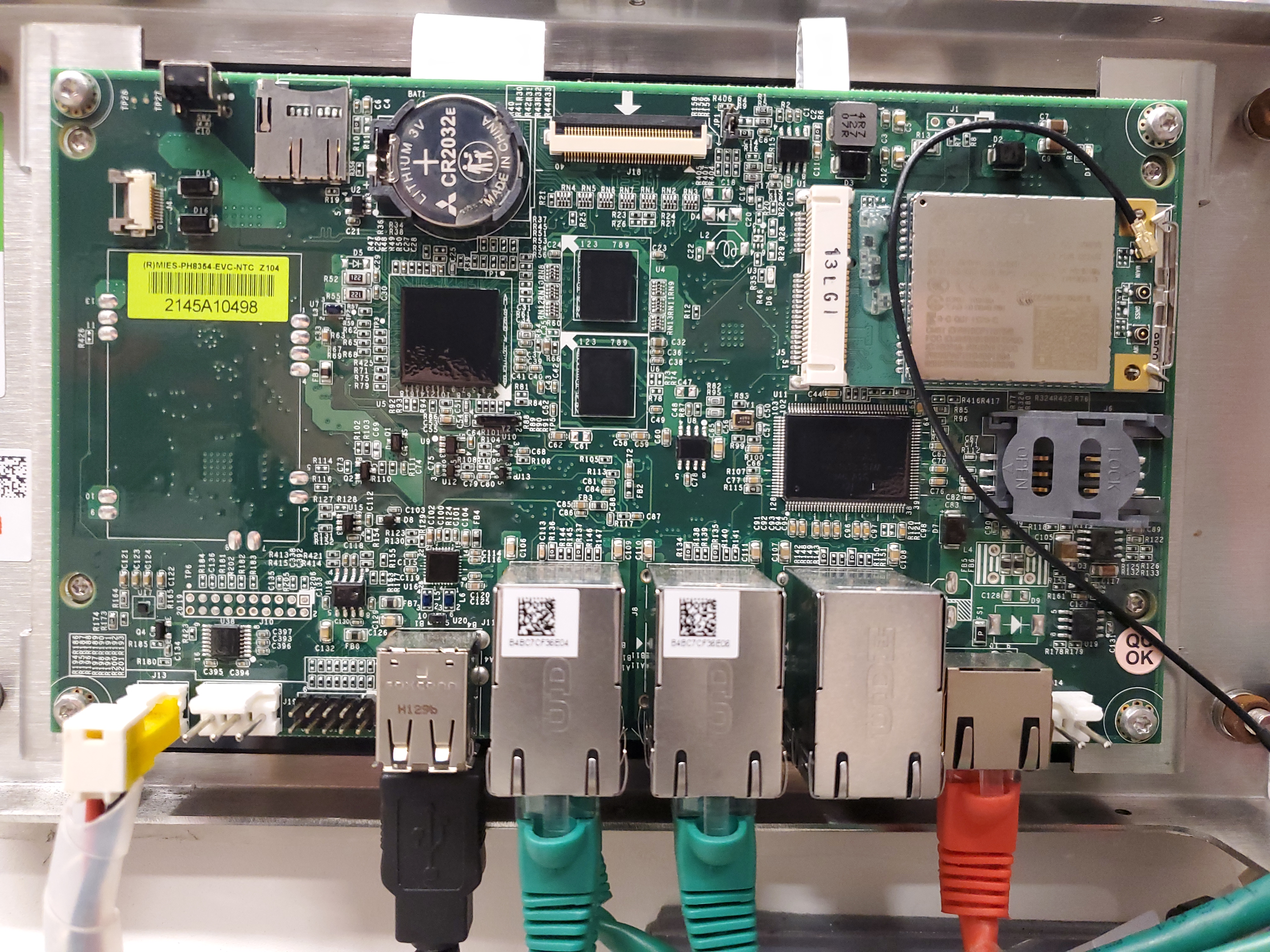
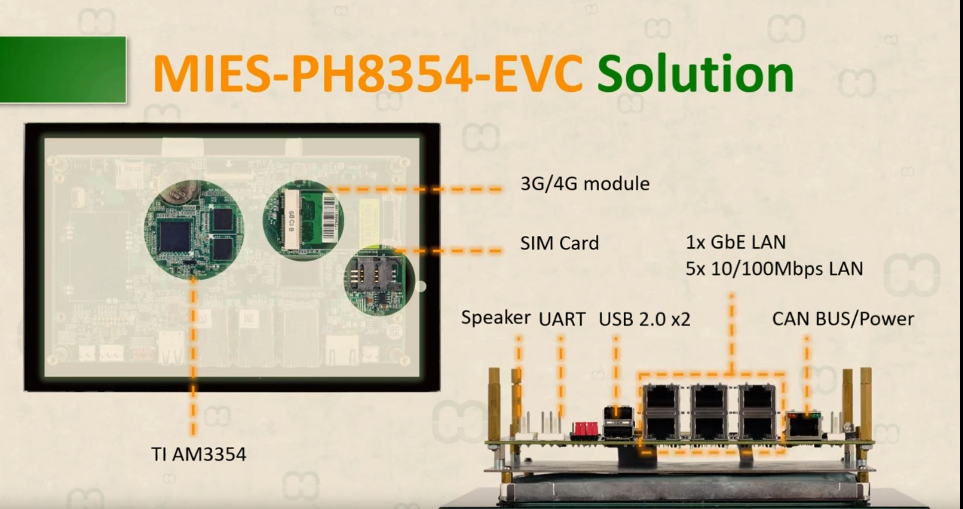
The first thing we learn, there's no way this thing actually runs windows, the TI chip is arm and the ram available is 1GB which is relatively small for "windows 10". The 'UART' port is 10 pins wide and has no visible pin designation, and without a datasheet that is a lot of guess and checking. Let's see if there's a data sheet somewhere. Maybe its pointing to the three pin connector instead? That could work as nominally its TX / RX / GND and fairly easy to sort out which is which. The vendor website lists this as "Engines of EV charger" [link], but there is not a lot of technical documentation. With a DMM sanity check lets verify the 3-pin connector is not like raw 24V and see if its UART communications. 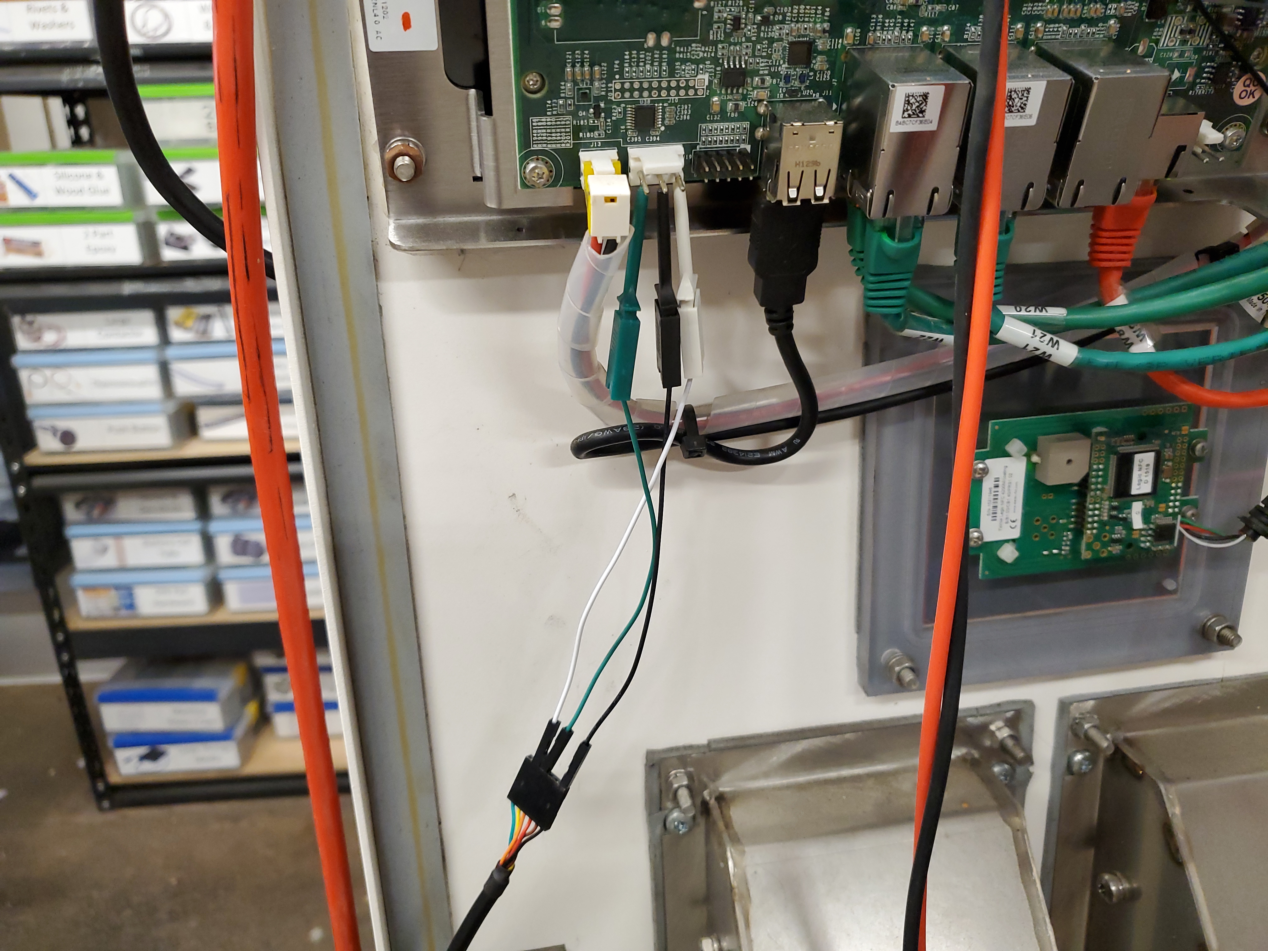
It is indeed UART, but its not very verbose. On re-boot, it wakes up and spits out is u-boot loading, it does not respond to text entry. Its possible it requires some jumper configuration to permit UART text entry, otherwise this is just printed out with nothing else. 
Lets make some 480VGiven that the charger is only booting up with the 24V logic power and entering a fault mode, lets see if giving the charger some 480V three phase results in the hardware waking up without a fault. Here's the problem, I do not have 480, but I do have 220 single phase and determination. There's a few times having 480 to wake-up hardware would be advantageous, so the plan is roughly the following: 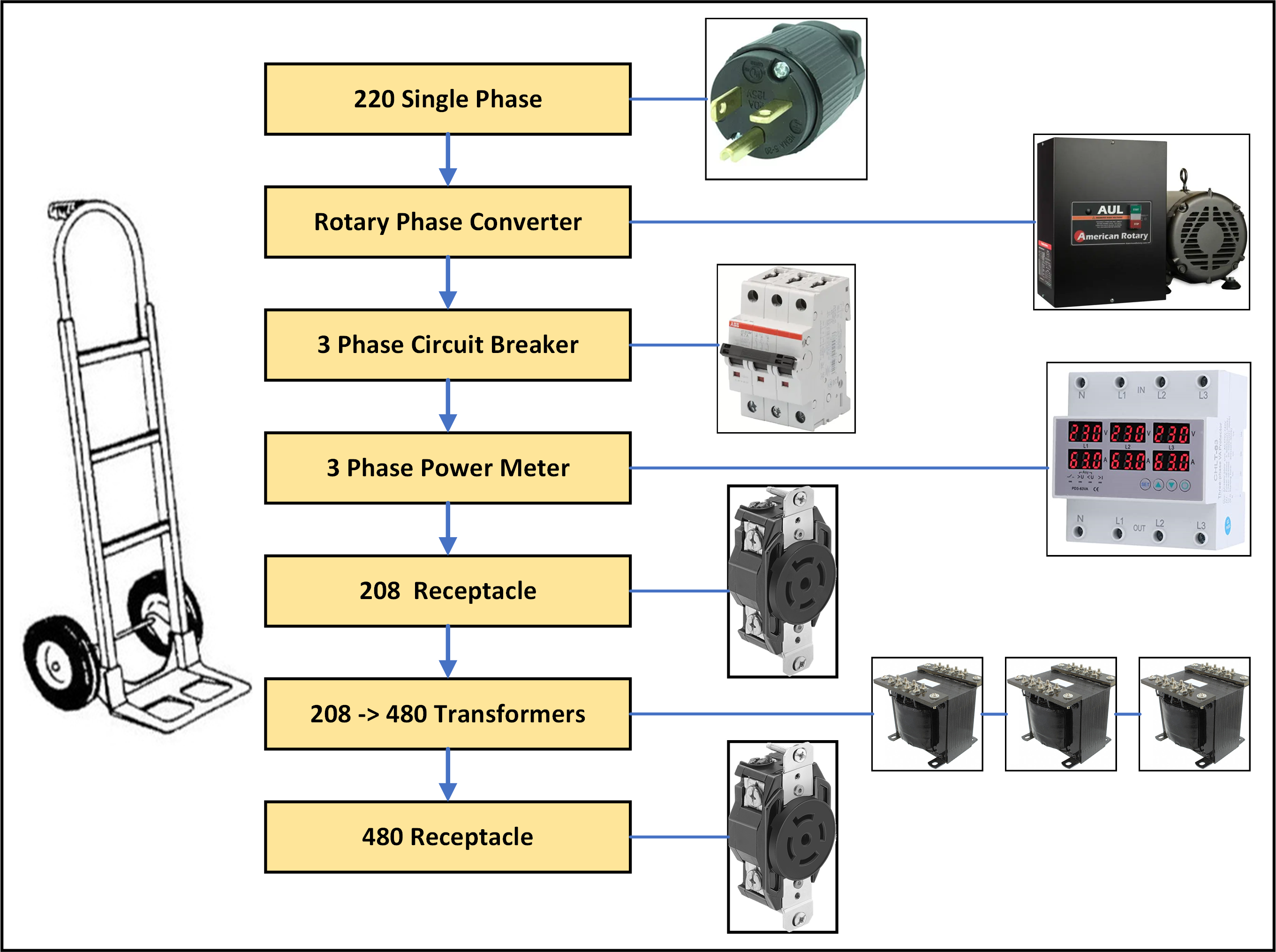
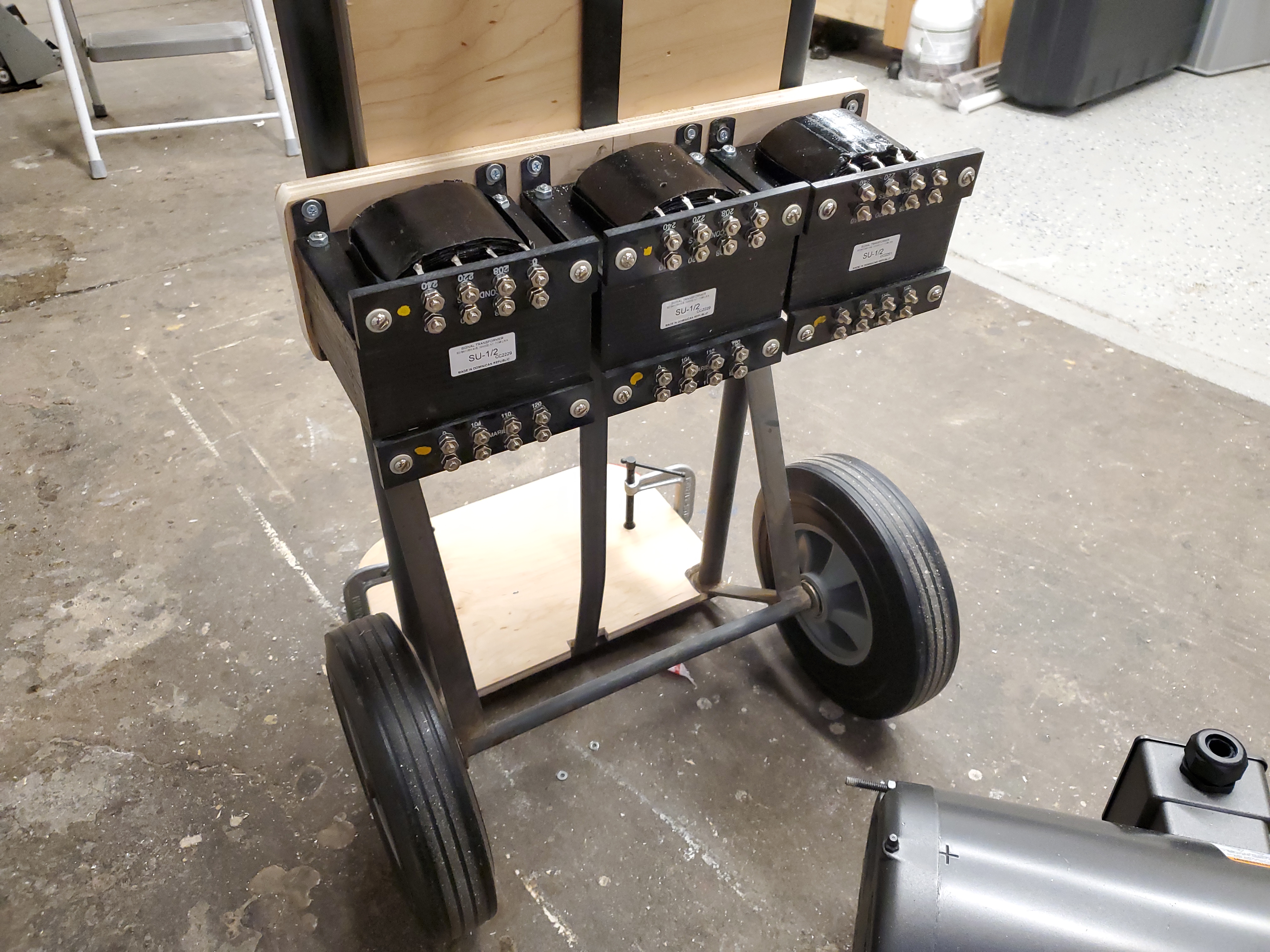
This is going to be somewhat heavy, so I'm going to opt to mount everything to a hand truck. There's almost always somewhat broken-wheel hand trucks hiding about the cobwebs of MIT basements, so I adopted one and replaced the wheels. Having an in-line breaker will also have the bonus of preventing overload if the startup to wake up the charger is huge. The limiting part of this setup is the 208->480 step up transformers, each is 0.5kva, so in total we can push 1.5kva maximum. The rotary phase converter is able to provide ~3.5kva. 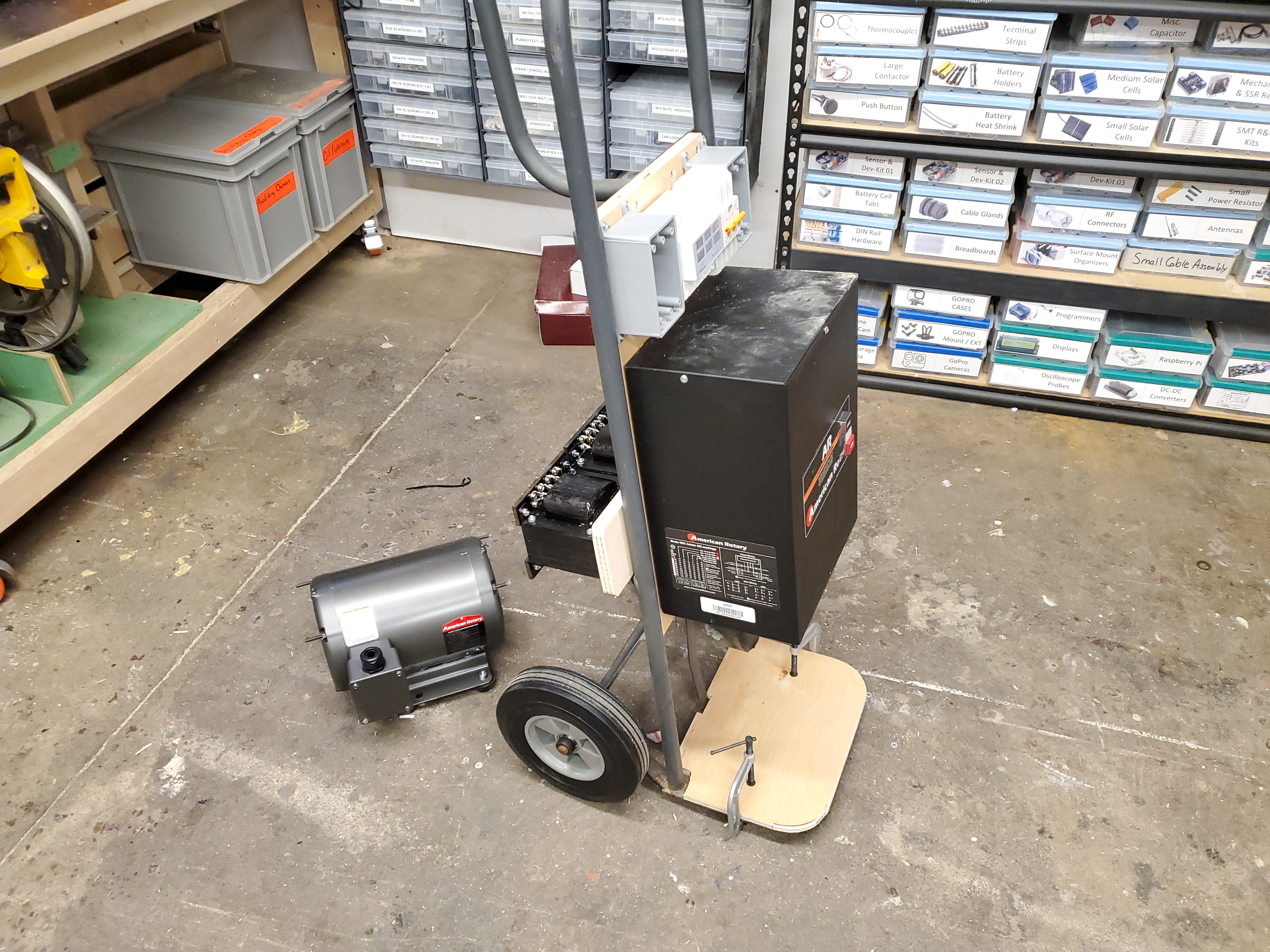
I added some vibration mounts for the rotary converter to help knock down any noise or rattling from being mounted directly to the donor hand truck. These were simple 1/4-20 female threaded mounts from mcmaster-carr [link], mounted to match up with the motor mount hole spacing. They worked remarkably well, but are strong enough to keep the motor in position even when the hand truck is laying down. 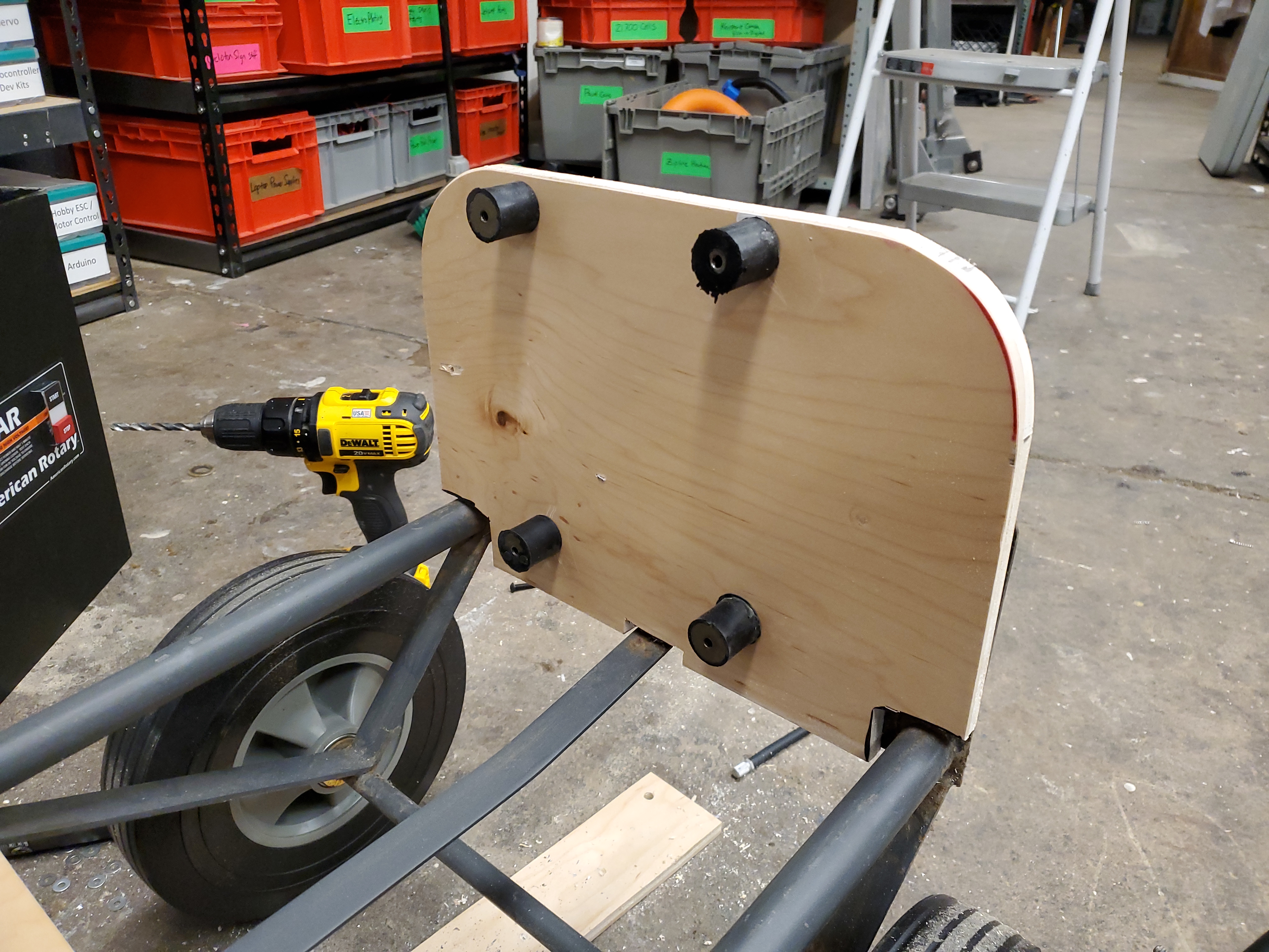
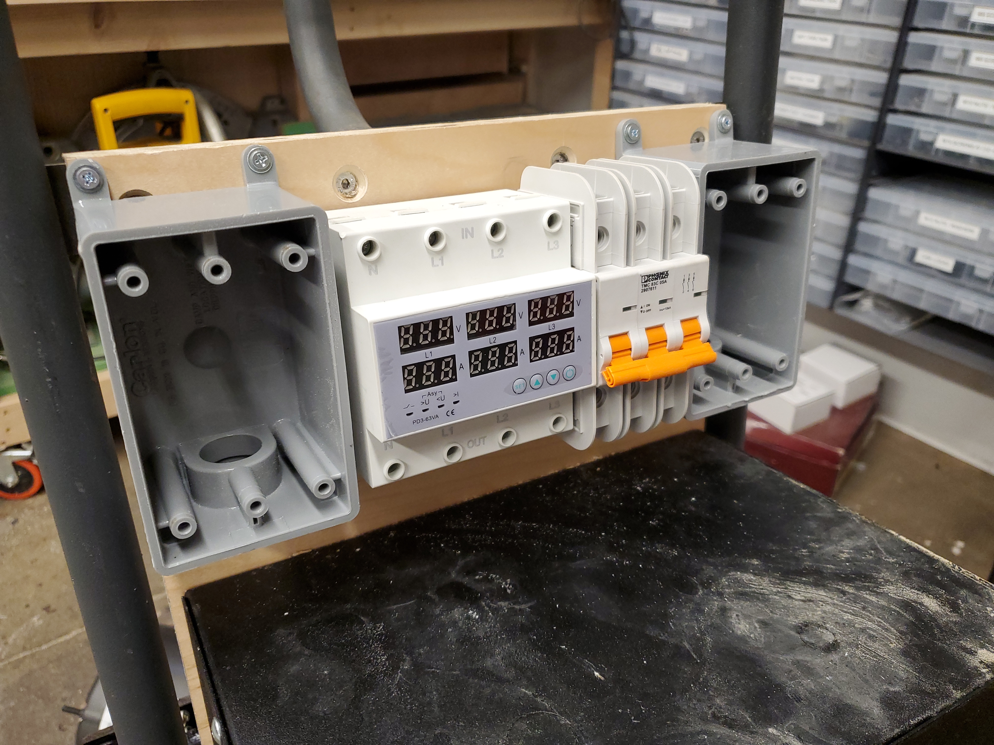
After some quick mounting of the rotary converter control box and three separate transformers, it was time to start wiring. I grabbed a 208 and 480 outlet and some cabling. The transformers do need some protective covers, as these are somewhat intended to live inside cabinets I imagine. Some printed covers should do the trick. The plan was to have a three phase circuit breaker between the rotary converter and everything else, with a three phase power meter before the step up transformers that generate the 480VAC. It turns out, the 'budget' three phase volts / amps meter was quite faulty, and even though i attempted to restore it, it was just not going to behave. This particular budget power meter would cycle between 0 and ~80 on the voltage display, almost as if it was intended for a different frequency application, or it was just incredibly faulty. 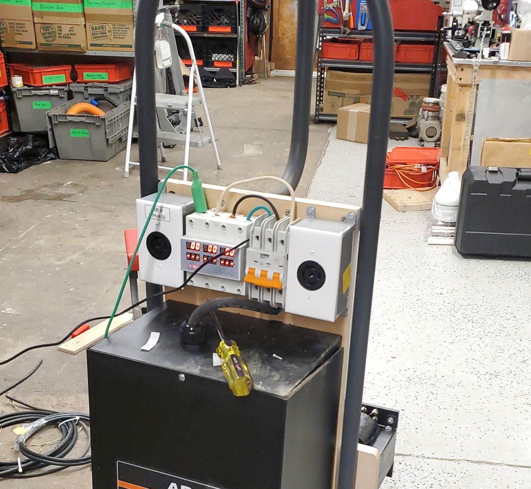
With everything wired up, I added a very incorrectly gauge 5 conductor cable and connector to the ABB charger. The '480 cart' had both a 208 three phase output and a 480 three phase output. This was sufficient to wake up the ABB charger, but it ended up having the same issue as when it was booted up with just the 24V rail powered. The little 480 cart does look fairly good next to the charger, It does need some wiring cleanup and some open terminal protection but everything worked out well for testing. The cart is missing one thing, googley eyes. 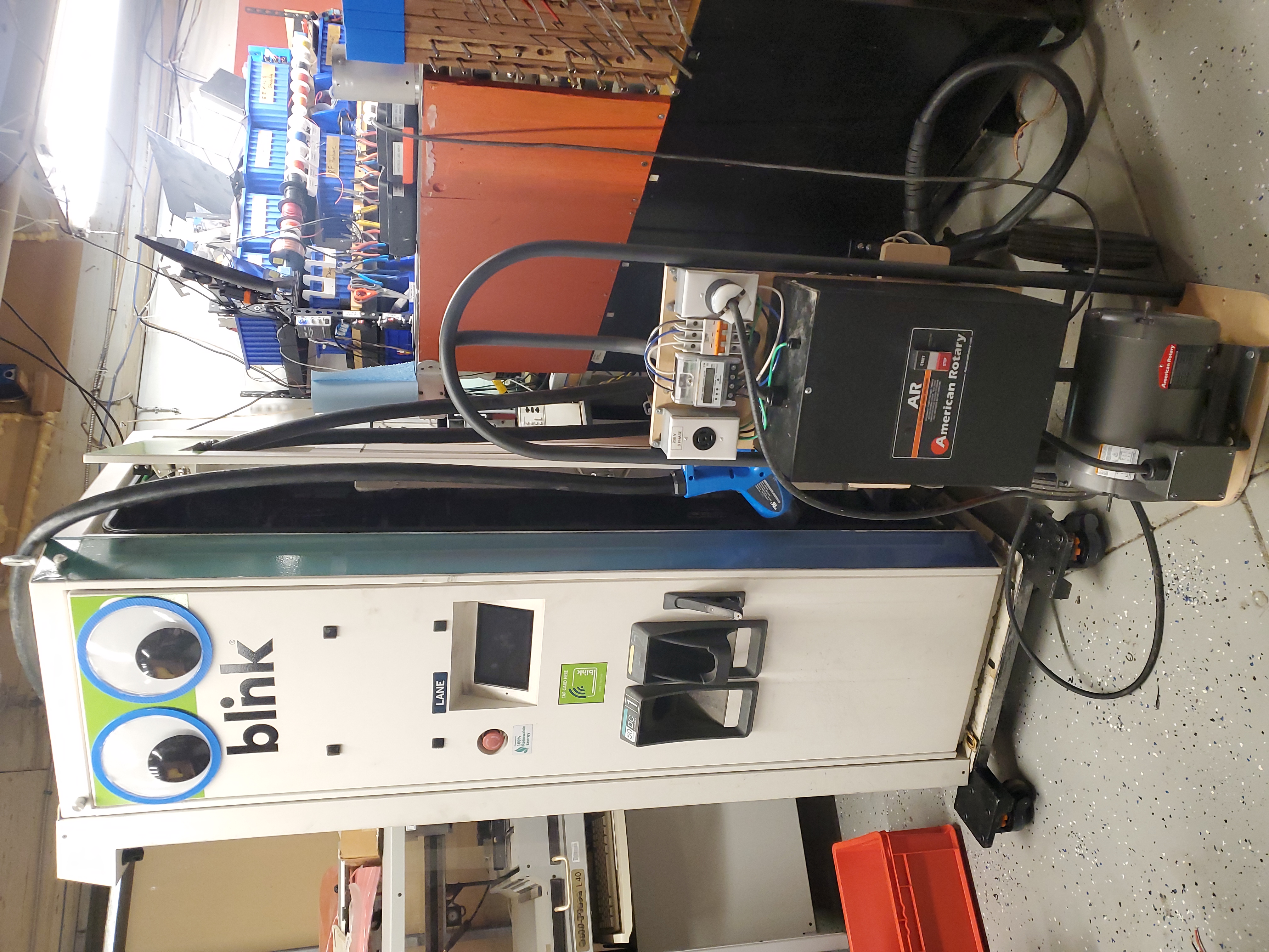
Have you noticed that there are no
advertisements or ridiculous pop ups?
|
Post your comments! |
|
Comment Box loading
|